Lombardini LDW 502 602 903 1204T 702 1003 1404 Service Manual – PDF DOWNLOAD
Original price was: $42.95.$15.95Current price is: $15.95.
Lombardini LDW 502 602 903 1204T 702 1003 1404 Service Manual – PDF DOWNLOAD
Description
Lombardini LDW 502 602 903 1204T 702 1003 1404 Service Manual – PDF DOWNLOAD
DESCRIPTION:
Lombardini LDW 502 602 903 1204T 702 1003 1404 Service Manual – PDF DOWNLOAD
FOREWORD:
We have done all in our power to give up to date and accurate technical information in this manual. Lombardini engines are, however, constantly developing thus the data in this publication may be liable to modification without prior notice. The information in this manual is the exclusive property of Lombardini. Neither partial nor total duplications or reprints are therefore permitted without the express authorization of Lombardini. The information in this manual is given on the assumption that:
1- the persons who service Lombardini engines have been adequately trained and outfitted to safely and professionally carry out the necessary tasks;
2- the persons who service Lombardini engines possess the necessary skills and special Lombardini tools to safely and professionally carry out the necessary tasks;
3- the persons who service Lombardini engines have read the specific information concerning the above mentioned Service operations and that they have clearly understood the operations required.
TABLE OF CONTENTS:
Lombardini LDW 502 602 903 1204T 702 1003 1404 Service Manual – PDF DOWNLOAD
SAFETY AND WARNING DECALS – SAFETY INSTRUCTIONS
I GENERAL
POWER RATINGS FOR LDW-FOCS GENSET SPEC DIESEL ENGINES
LDW FOCS SERIES – TECHNICAL SPECIFICATIONS AND CAPACITIES LDW 502-602-
903-1204-1204/T
FLUID CAPACITIES (STANDARD) LDW 502-602-903-1204-1204/T
LDW FOCS SERIES – TECHNICAL SPECIFICATIONS AND CAPACITIES LDW 702-1003-
1404
FLUID CAPACITIES (STANDARD) LDW 702-1003-1404
POWER, TORQUE AND SPECIFIC FUEL CONSUMPTION CURVES LDW 502-602-903
POWER, TORQUE AND SPECIFIC FUEL CONSUMPTION CURVES LDW 1204-1204/T
POWER, TORQUE AND SPECIFIC FUEL CONSUMPTION CURVES LDW 702-1003-1404
GENERAL ENGINEERING DRAWINGS – LDW 502-602-903
GENERAL ENGINEERING DRAWINGS – LDW 1204-1204/T
GENERAL ENGINEERING DRAWINGS – LDW 702-1003-1404
LDW-FOCS SERIES MAINTENANCE SCHEDULE
RECOMMENDED OIL
DIESEL FUEL SPECIFICATIONS
ANTI-FREEZE / COOLANT SPECIFICATIONS / DETAILS – FOCS SERIES
DRIVING TORQUES FOR STANDARD SCREWS
SEALANT AND THREAD LOCK LOCATIONS/DETAILS
CRITICAL TORQUE SPECIFICATIONS
SPECIAL TOOLS
II DISASSEMBLY / REASSEMBLY
Air filter support – (intake manifold)
Air restriction switch
Alternator / cooling fan drive belt
Camshaft journal / support bore specifications
Camshaft journal / support measurement
Camshaft lobe measurement procedure
Camshaft lobe specifications
Camshaft removal / replacement
Camshaft timing pulley
Connecting bearing / rod cap installation
Connecting rod / connecting rod bearings specifications
Connecting rod alignment
Connecting rod-piston assembly balance
Cooling fan
Cooling fan support
Crankcase breather – LDW 502
Crankcase vacuum regulator valve (602, 702, 903, 1003, 1204, 1204/t, 1404)
Crankshaft end play
Crankshaft journal inspection / measurement
Crankshaft journal specifications
Crankshaft lubrication drillings-typical
Crankshaft pulley
Crankshaft seals – front and rear
This manual contains pertinent information regarding the repair of LOMBARDINI water-cooled,
indirect injection Diesel engines type LDW 502-602-903-1204-124/T and LDW 702-1003-
INDEX
COMPILER TECO/ATL REG. CODE
1-5302-351
MODEL N°
50563
DATE OF ISSUE
04.90
REVISION 04 DATE ENDORSED
15.11.99 5
Crankshaft timing pulley
Cylinder class
Cylinder head installation
Cylinder head removal
Cylinder head tightening procedure- LDW 1204, LDW 1404, LDW 1204/T
Cylinder head tightening procedure- LDW 502, 602, 702, 903 and 1003
Cylinder inspection / dimensional specifications
Cylinder surface finish
Dry type air filter- standard engine mounted
Exhaust manifold
Flywheel / ring gear
Front / rear main bearing caps / bearings
Fuel rail
Fuel tank – (optional accessory)
General piston notes
Governor fork
Governor springs
Head gasket selection/ installation
Hydraulic drive components- no. 3 pto
Hydraulic pump pto- (no. 3 pto)
Idler pulley
Injection pump control rod
Limiting speed governor
Main and connecting rod bearings
Main bearing caps / bearings- center
Main bearing clearance
No. 2 pto (crankshaft pulley) with “ringfeder”- LDW 1204, LDW 1204/T, LDW 1404
Oil bath air filter
Oil pan removal / installation
Oil pump assembly
Oil pump assembly to the engine
Oil pump inspection
Piston / connecting rod disassembly and piston inspection
Piston / connecting rod installation
Piston balance
Piston class, weight imbalance and genuine lombardini markings
Piston cooling jets- ldw 1204/t
Piston protrusion
Piston removal
Piston ring assembly location
Piston ring end gap
Piston ring to piston land clearance
Piston wrist pin installation / retaining snap ring
Precision speed governor -(gensets)
Pre-combustion chamber installation
Pre-combustion chamber removal
Pre-combustion chamber ring nut
Pre-combustion chamber-overview
Rocker arm assembly
Speed governor
Speed governor reassembly
Thrust bearings
Thrust surface specifications-crankshaft end play corrections
Timing belt / timing pulley arrangement
Timing belt cover
Timing belt installation- timing procedure
Timing belt removal
Timing belt tension procedure
Timing belt tensioning procedure- setup
Timing pulley – reference marks
Undersized bearings- rod and main
Unit injector check valve
Unit injector removal / installation
Valve / rocker cover
REG. CODE
1-5302-351
MODEL N°
50563
DATE OF ISSUE
04.90
REVISION 04 DATE
15.11.99
COMPILER TECO/ATI ENDORSED 6
Valve / rocker cover gasket
Valve adjustment
Valve guide installation guidelines and post installation valve/valve guide specifications
Valve guides / valve guide bore
Valve recess and seat sealing width
Valve removal
Valve seats
Valve specifications
Valve springs
Valve stem seal installation
Valve timing angles
Valve timing confirmation
III TURBOCHARGER
Turbocharger identification
Turbocharger components
Turbocharger pressure testing
Turbocharger waste gate adjustement-bench method
IV LUBRICATION SYSTEM
Lubrication system
Oil pick-up screen and oil drain back tube
Oil pump specification
Oil filter
Oil pressure testing
V COOLING SYSTEM
LDW-FOCS cooling system schematic
Cooling system pressure check/radiator cap inspection
Coolant pump details
Thermostat
VI FUEL SYSTEM
Barrel and plunger detail- (typical) current unit injectors (example- 6590-285)
Barrel and plunger detail- early unit injectors (typical)
Early unit injectors
Engine timing reference marks
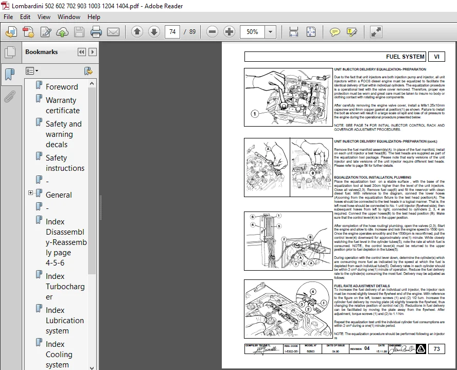
Equalization tool installation, plumbing
Fuel filter assembly
Fuel rate adjustment details
Fuel system schematic
Fuel system special tools
Fuel transfer pump
Fuel transfer pump push rod protrusion
Injector
Injector nozzle protrusion
Late/ intermediate unit injectors
Static injection test instrumentation- early unit injectors
Static timing adjustment
Tdc determination and static injection timing checking
Unit injector
Unit injector components
Unit injector delivery equalization- preparation
Unit injector delivery equalization- preparation (cont.)
Unit injector fire ring
Unit injector plunger reassembly
Unit injector popping pressure testing and adjustment- low pressure procedure (current / intermediate
unit injectors)
COMPILER TECO/ATL REG. CODE
1-5302-351
MODEL N°
50563
DATE OF ISSUE
04.90
REVISION 04 DATE ENDORSED
15.11.99 7
Unit injector popping pressure testing and adjustment- high pressure procedure (early unit
injectors- all ref. No’s other than 272, 272-, 272-1, 235-3)
Unit injector reassembly (cont.)
Unit injector ring nut removal / replacement
Unit injector test stand specifications
VII ELECTRICAL SYSTEM
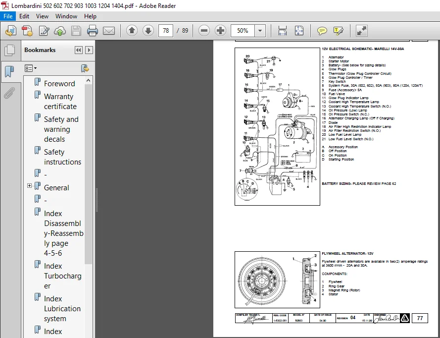
12 electrical schematic-marelli 14V-33A
12V electrical schematic – 20/30 A flywheel alternator
12V electrical schematic-iskra 14V-33A
Battery sizing
Battery sizing
Bosch 12V/1.1 kW starter motor (DW 12V)
BOSCH 12V/1.6 kW starter motor (DW 12V)
Electrical system service precautions / warning
Engine side wiring harness for the Lombardini supplied control panel
Flywheel alternator – 12V
Glow plug
Glow plug controller / relay with coolant temp. Sensor
Iskra 14V/33A performance curve
Iskra alternator – 14V/33A
Lombardini supplied control panel
Marelli AA 125 R, 14V/45A performance curve
Marelli alternator (AA 125 R) – 14V-45A
Oil pressure (low) switch, coolant temperature (high) switch
Performance curve – 20A flywheel alternator
Performance curve – 30A flywheel alternator
Performance curve – BOSCH 12V/1.1 kW (DW 12V) starter
Performance curve – BOSCH 12V/1.6 kW (DW 12V) starter
Temperature sensor (thermistor)
Voltage regulator connection details (flywheel alternator only)
VIII TESTING-OPERATIONAL-ADJUSTEMENTS
Governor / unit injector rack adjustment
High (maximum) speed adjustment
Idle speed adjustment
Injection pump control rod stroke limit adjustment
Power, torque device and speed adjustments-dynamometer method
Torque device adjustment (without dynamometer)
Torque device details
IX STORAGE
Storage
Storage – 1 to 6 months
Storage – in excess of 6 months
Preparing the engine for use after storage
LOMBARDINI LDW 502 602 903 1204T 702 1003 1404 SERVICE MANUAL – PDF DOWNLOAD:
IMAGES PREVIEW OF THE MANUAL:
PLEASE NOTE:
- This is the same manual used by the DEALERSHIPS to SERVICE your vehicle.
- The manual can be all yours – Once payment is complete, you will be taken to the download page from where you can download the manual. All in 2-5 minutes time!!
- Need any other service / repair / parts manual, please feel free to contact us at heydownloadss @gmail.com . We may surprise you with a nice offer
Dustin Noel –
It was easy, quick, and convenient-what I was looking for. The quality of the product could have been a bit better but overall, it works.