Lull 844B Telehandler Parts Manual – PDF DOWNLOAD
Original price was: $90.00.$21.95Current price is: $21.95.
Lull 844B Telehandler Parts Manual – PDF DOWNLOAD
10709911
Description
Lull 844B Telehandler Parts Manual – PDF DOWNLOAD
FILE DETAILS:
Lull 844B Telehandler Parts Manual – PDF DOWNLOAD
Format: PDF
Language: English
Brand: LULL
TABLE OF CONTENTS:
Lull 844B Telehandler Parts Manual – PDF DOWNLOAD
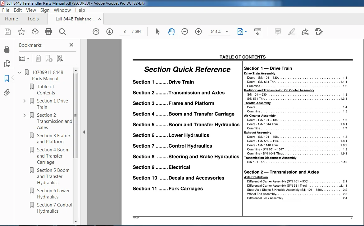
Section Quick Reference
Drive Train
Transmission and Axles Section
Frame and Platform
Boom and Transfer Carriage Section Boom and Transfer Hydraulics Section
Lower Hydraulics
Section 7 Control Hydraulics
Section 8 Steering and Brake Hydraulics Section
Electrical
Section 10 .Decals and Accessories Section
Fork Carriages
Section 1 – Drive Train
Drive Train Assembly
Deere – S/N 101 – 530
Deere- S/N 531 Thru .
Cummins
Radiator and Transmission Oil Cooler Assembly
S/N 101 – 530
S/N 531 Thru
Throttle Assembly
Deere
Cummins .
Air Cleaner Assembly
Deere- S/N 101 -1343.
Deere – S/N 1344 Thru
Cummins
Exhaust Assembly
Deere
Deere
Deere
Cummins
Cummins
Transmission Disconnect Assembly
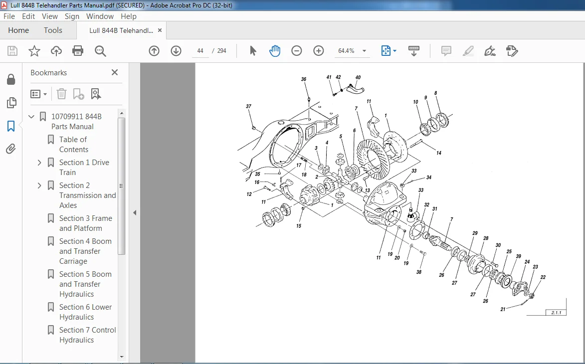
Section 2 – Transmission and Axles
Axle Breakdown
Differential Carrier Assembly (S/N 101 – 530).
Differential Carrier Assembly (S/N 531 Thru) .
Steer Axle Shafts & Knuckle Assembly
Wheel End Assembly
Differential Lock Assembly
Funk Transmission Breakdown (SIN 101 – 530)
Main Case Assembly .
Output Retainer Assembly
Output Shaft Assembly
Clutch Assembly, 1st Stage
Clutch Assembly, 2nd Stage
Clutch Assembly, 3rd Stage
Front Cover Assembly
Input Shaft Assembly
Valve Control Assembly
Pump Assembly
Drive Plate Assembly .
Converter Assembly .
Parking Brake & Yoke Assembly
ZF Transmission Breakdown (SIN 531 Thru)
Converter & Flex Plate Assembly. . . . . . . . . . . . . . . . . . . . . . . . . . . . 2.18
Gearbox Housing Assembly . . . . . . . . . . . . . . . . . . . . . . . . . . . . . . . . 2.19
Input Group & Layshaft Assembly ……………………… 2.20
Clutch Assembly, Forward & 1st Gear …………………… 2.21
Clutch Assembly, Reverse & 2nd Gear ………………….. 2.22
Clutch Assembly, 3rd Gear ………………………….. 2.23
Clutch Assembly, 4th Gear . . . . . . . . . . . . . . . . . . . . . . . . . . . . . . . . 2.24
Output Group Assembly . . . . . . . . . . . . . . . . . . . . . . . . . . . . . . . . . . . 2.25
Power Take-off & Filter Assembly ………………………. 2.26
Gearshift System Assembly ………………………….. 2.27
Control Valve Assembly . . . . . . . . . . . . . . . . . . . . . . . . . . . . . . . . . . . 2.28
Oil Tubes & Dipstick Assembly. . . . . . . . . . . . . . . . . . . . . . . . . . . . . . 2.29
Parking Brake Assembly. . . . . . . . . . . . . . . . . . . . . . . . . . . . . . . . . . . 2.30
Section 3 – Frame and Platform
Main Frame Assembly (S/N 101 – 1139) . . . . . . . . . . . . . . . . . . . . . . . 3.1
Main Frame Assembly (S/N 1140 Thru) ………………….. 3.1.1
Operators Platform Assembly (S/N 101 – 536 & 538) . . . . . . . . . . . . . 3.2
Operators Platform Assembly (S/N 537, 539 Thru) ………….. 3.2.1
Instrument Panel Assembly (S/N 101-530) …………………. 3.3
Instrument Panel Assembly (S/N 531 Thru) . . . . . . . . . . . . . . . . . . . 3.3.1
Section 4 – Boom and Transfer Carriage
Telescopic Boom Assembly ……………………………. 4.1
Transfer Carriage Assembly …………………………… 4.2
Section 5 – Boom and Transfer Hydraulics
Boom Hydraulic Assembly (S/N 101-192, 194-266 & 268-272) ….. 5.1
Boom Hydraulic Assembly (S/N 193, 267 & 273 – 1283) ……….5.1.1
Boom Hydraulic Assembly (S/N 1284 Thru) ………………..5.1.2
Boom Extension Cylinder Assembly ……………………… 5.2
Front Carriage Tilt Cylinder Assembly …………………….. 5.3
Hoist – Transfer Hydraulic Assembly ……………………… 5.4
Hoist Cylinder Assembly ……………………………… 5.5
Tranter Cylinder Cylinder Assembly ……………………… 5.6
Rear Carriage Tilt Cylinder Assembly …………………….. 5.7
Section 6 – Lower Hydraulics
Pump, Suction-Return Hydraulics Assembly ………………… 6.1
Hydraulic Return Line Filter Assembly (Original Equipment) ……… 6.2
Hydraulic Return Line Filter Assembly (Service Replacment) …….6.2.1
Frame Hydraulic Assembly ……………………………. 6.3
Frame Tilt Cylinder Assembly ………………………….. 6.4
Hydraulic Control Valve Assembly (S/N 101 – 536 & 538) ………. 6.5
Valve Section Assembly – Carriage Fork Tilt (S/N 101-536 & 538) … 6.6
Valve Section Assembly – Transfer Carriage (S/N 101-536 & 538) … 6.7
Valve Section Assembly – Frame Tilt/ Auxiliary
(S/N 101-536 & 538) .
Hydraulic Control Valve Assembly (S/N 537, 539 Thru)
Valve Section Assembly – Transfer Carriage/ Frame Tilt/ Auxiliary
(S/N 537, 539 Thru)
Valve Section Assembly – Carriage Fork Tilt (S/N 537, 539 Thru)
Test Port Hydraulic Assembly
Section 7 – Control Hydraulics
Joystick Control Hydraulics (S/N 101 – 536 & 538) …………….7.1
Joystick Control Hydraulics (S/N 537, 539 Thru) ……………. 7.1.1
Hydraulic (Boom) Control Valve Assembly …………………..7.2
Relief Valve Assembly ………………………………..7.3
Joystick Control Assembly (S/N 101 – 536 & 538) ……………..7.4
Joystick Control Assembly (S/N 537, 539 Thru) …………….. 7.4.1
Frame Tilt Control Assembly (S/N 537, 539 Thru) ……………..7.5
Circuit Selector Valve Assembly (S/N 537, 539 Thru) …………..7.6
Pressure Filter Assembly ………………………………7.7
Section 8 – Brake Assembly
Hydraulic Steering & Differential Lock Assembly ………………8.1
Hydraulic Service Brake Assembly (S/N 101 – 123} …………….8.2
Hydraulic Service Brake Assembly (S/N 124 Thru) ………….. 8.2.1
Accumulator Assembly ………………………………..8.3
Parking Brake Assembly (S/N 101 – 530) …………………..8.4
Parking Brake Assembly (S/N 531 Thru) …………………. 8.4.1
Parking Brake Valve Assembly (S/N 531 Thru) ……………….8.5
Section 9 – Electrical
Electrical Group – Operator’s Compartment ………………….9.1
Electrical Assembly – Deere (S/N 101 – 530) …………………9.2
Electrical Assembly – Deere (S/N 531 Thru) ……………….. 9.2.1
Electrical Assembly – Cummins ………………………….9.3
Section 1O – Decal and Accessories
Decal Group Assembly ……………………………….10.1
Accessories
Side Panel Assembly ……………………………….. 10.2
2nd Auxiliary! Hydraulic Assembly (S/N 101 – 536 & 538) ……… 10.3
2nd Auxiliary! Hydraulic Assembly (S/N 537, 539 Thru) ……….10.3.1
Outrigger Assembly (S/N 101 – 536 & 538) ……………….. 10.4
Outrigger Assembly (S/N 537, 539 Thru) …………………10.4.1
Outrigger Extension Cylinder Assembly . . . . . . . . . . . . . . . . . . . . . . . 10.5
Cab Assembly ……………………………………. 10.6
Cab Insulation Group Assembly ……………………….. 10.7
Cab Door Assembly (S/N 101 – 353) ……………………. 10.8
Cab Door Assembly (S/N 354 Thru) …………………….10.8.1
Cab Heater, Wiper & Defroster Assembly …………………. 10.9
Heater Assembly (Optional Cab) ………………………. 10.10
Roadway Lighting Assembly …………………………. 10.11
Work Lights Assembly ……………………………… 10.12
Section 11 – Fork Carriages
Standard (Non-Tilt) Fork Carriage Assembly. . . . . . . . . . . . . . . . . . . . 11.1
Framers (Non-Tilt} Fork Carriage Assembly ……………….. 11.2
Standard Tilting Fork Carriage Assembly . . . . . . . . . . . . . . . . . . . . . . 11.3
Framers Tilting Fork Carriage Assembly . . . . . . . . . . . . . . . . . . . . . . . 11.4
Tilt Carriage Cylinder Assembly ……………………….. 11.5
Tower Assembly ………………………………….. 11.6
Tower Cylinder Assembly ……………………………. 11.7
Standard (Non-Tilt) Tower Carriage Assembly ……………… 11.8
Standard Tilting Tower Carriage Assembly ………………… 11.9
Section 1 — Drive Train
WW
Deere-Sthm—530………………….
Deere-S/N531Thru…………………..
Cummlns
Radiator and Transmission Oil Cooler Assembly
S/N101—530………………………..
S/N531‘i‘hru…………………………
Throttle Assembly
Deere
Air Cleaner Assembly
Deere-S/N101-1343…………………
Deere-SfN1344Thru………………….
Cummlns
Exhaust Assembly
Deere-SfN101—558………………….
Deere-S/N559-1139…………………
Deere-SfN114OThru………………….
Cummins-S/N101—1047……………….
Cummins-SIN1048Thru……………….
Transmission Disconnect Assembly
S/N101171m…………………………
LULL 844B TELEHANDLER PARTS MANUAL – PDF DOWNLOAD:
IMAGES PREVIEW OF THE MANUAL:
PLEASE NOTE:
- This is the same manual used by the dealers to diagnose and troubleshoot your vehicle
- You will be directed to the download page as soon as the purchase is completed. The whole payment and downloading process will take anywhere between 2-5 minutes
- Need any other service / repair / parts manual, please feel free to contact [email protected] . We still have 50,000 manuals unlisted
Ayan Henrik –
always a pleasure
Bryce Fisher –
it was good