LULL D SERIES TELEHANDLER PARTS MANUAL – PDF DOWNLOAD
Original price was: $80.00.$21.95Current price is: $21.95.
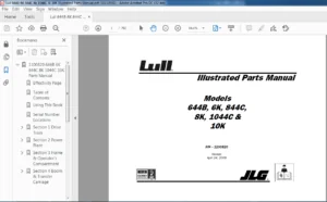
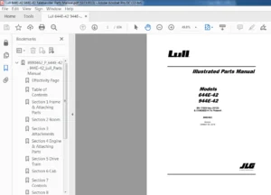
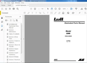
LULL D SERIES TELEHANDLER PARTS MANUAL – PDF DOWNLOAD
1100830-005
Description
LULL D SERIES TELEHANDLER PARTS MANUAL – PDF DOWNLOAD
FILE DETAILS:
LULL D SERIES TELEHANDLER PARTS MANUAL – PDF DOWNLOAD
Format: PDF
Language: English
Brand: JLG GRADALL
TABLE OF CONTENTS:
LULL D SERIES TELEHANDLER PARTS MANUAL – PDF DOWNLOAD
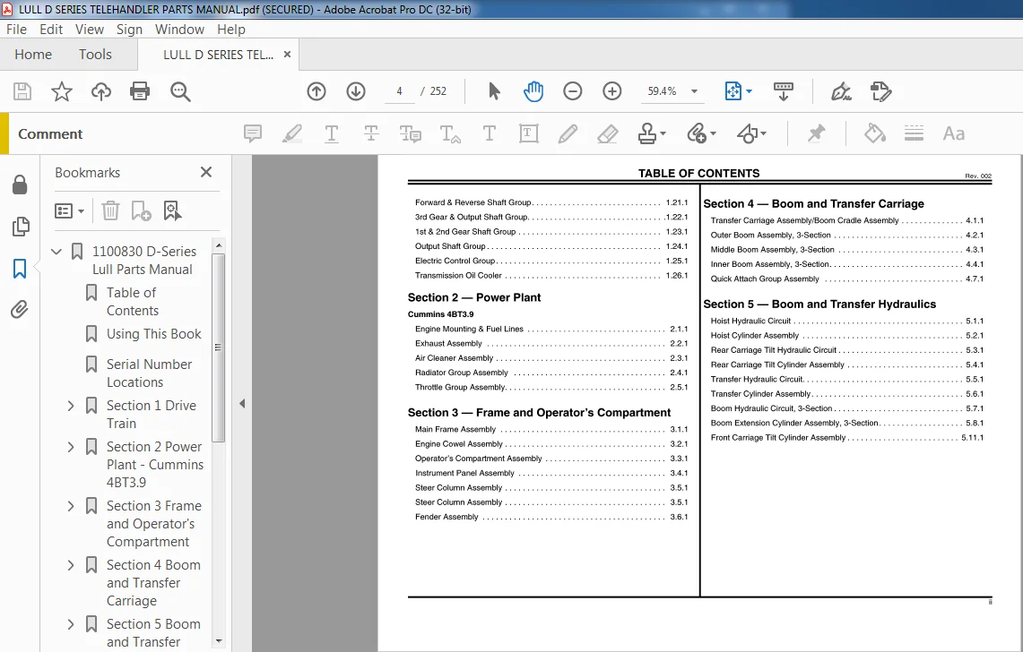
TABLE OF CONTENTS Rev. 002
Section Quick Reference
Section 1 ……… Drive Train
Section 2 ……… Power Plant
Section 3 ……… Frame and Operator’s
Section 4 ……… Boom and Transfer Carriage
Section5 ……… Boom and Transfer Hydraulics
Section 6 ……… Pump, Suction – Return and
Section 8 …….. Steering and Brake Hydraulics
Section 9 ……… Electrical
Section 1O ……. Decals and
General Information
Useing this book……………………………………….iv
Ordering Parts ………………………………………..vi
Serial Number Locations …………………………………vi
Section 1 – Drive Train
Drive Train Group Assembly …………………………… 1.1.1
Transmission Output Drive Shaft Assembly…………………. 1.2.1
Intermediate Drive Shaft Assembly ………………………. 1.3.1
Front & Rear Drive Shaft Assembly. . . . . . . . . . . . . . . . . . . . . . . . . . . . 1.4.1
Axles (420S)
Axle Housing Assembly Right Front & Left Rear . . . . . . . . . . . . . . . . . . 1.5.1
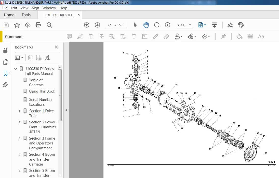
Axle Housing Assembly Left Front & Right Rear ……………… 1.6.1
Center Gear Box Assembly ……………………………. 1.7.1
Differential Carrier Assembly – Front Axle (Limited Slip) ………… 1.8.1
Differential Carrier Assembly – Rear Axle (Standard) ………….. 1.9.1
Brake Box Assembly – Front Axle . . . . . . . . . . . . . . . . . . . . . . . . . . 1.10.1
Brake Box Assembly – Rear Axle. . . . . . . . . . . . . . . . . . . . . . . . . . . . . 1.11.1
Wheel End, Steer Axle Shafts & Knuckle Assembly ………….. 1.12.1
Steer Cylinder Assembly …………………………….. 1.13.1
Transmission T-12000
Converter Housing Assembly ………………………….. 1.15.1
Transmission Case & Plate Assembly ……………………. 1.16.1
Torque Converter Assembly . . . . . . . . . . . . . . . . . . . . . . . . . . . . . . . . 1.17.1
Pump Drive Group . . . . . . . . . . . . . . . . . . . . . . . . . . . . . . . . . . . . . . . . 1.18.1
Charging Pump & Filter Assembly ………………………. 1.19.1
Reverse Idler Group………………………………… 1.20.1
TABLE OF CONTENTS Rev. 002
Forward & Reverse Shaft Group. . . . . . . . . . . . . . . . . . . . . . . . . . . . . 1.21.1
3rd Gear & Output Shaft Group………………………….1.22.1
1st & 2nd Gear Shaft Group . . . . . . . . . . . . . . . . . . . . . . . . . . . . . . . . 1.23.1
Output Shaft Group . . . . . . . . . . . . . . . . . . . . . . . . . . . . . . . . . . . . . . . 1.24.1
Electric Control Group. . . . . . . . . . . . . . . . . . . . . . . . . . . . . . . . . . . . . 1.25.1
Transmission Oil Cooler . . . . . . . . . . . . . . . . . . . . . . . . . . . . . . . . . . . 1.26.1
Section 2 – Power Plant
Cummins 4BT3.9
Engine Mounting & Fuel Lines . . . . . . . . . . . . . . . . . . . . . . . . . . . . . . . 2.1.1
Exhaust Assembly . . . . . . . . . . . . . . . . . . . . . . . . . . . . . . . . . . . . . . . . 2.2.1
Air Cleaner Assembly . . . . . . . . . . . . . . . . . . . . . . . . . . . . . . . . . . . . . . 2.3.1
Radiator Group Assembly . . . . . . . . . . . . . . . . . . . . . . . . . . . . . . . . . . 2.4.1
Throttle Group Assembly ……………………………… 2.5.1
Section 3 – Frame and Operator’s Compartment
Main Frame Assembly . . . . . . . . . . . . . . . . . . . . . . . . . . . . . . . . . . . . . 3.1.1
Engine Cowel Assembly . . . . . . . . . . . . . . . . . . . . . . . . . . . . . . . . . . . . 3.2.1
Operator’s Compartment Assembly . . . . . . . . . . . . . . . . . . . . . . . . . . . 3.3.1
Instrument Panel Assembly . . . . . . . . . . . . . . . . . . . . . . . . . . . . . . . . . 3.4.1
Steer Column Assembly . . . . . . . . . . . . . . . . . . . . . . . . . . . . . . . . . . . . 3.5.1
Steer Column Assembly . . . . . . . . . . . . . . . . . . . . . . . . . . . . . . . . . . . . 3.5.1
Fender Assembly . . . . . . . . . . . . . . . . . . . . . . . . . . . . . . . . . . . . . . . . . 3.6.1
Section 4 – Boom and Transfer Carriage
Transfer Carriage Assembly/Boom Cradle Assembly ………….. 4.1.1
Outer Boom Assembly, 3-Section ……………………….. 4.2.1
Middle Boom Assembly, 3-Section ………………………. 4.3.1
Inner Boom Assembly, 3-Section ………………………… 4.4.1
Quick Attach Group Assembly …………………………. 4.7.1
Section 5 – Boom and Transfer Hydraulics
Hoist Hydraulic Circuit ……………………………….. 5.1.1
Hoist Cylinder Assembly ……………………………… 5.2.1
Rear Carriage Tilt Hydraulic Circuit ………………………. 5.3.1
Rear Carriage Tilt Cylinder Assembly …………………….. 5.4.1
Transfer Hydraulic Circuit. …………………………….. 5.5.1
Transfer Cylinder Assembly ……………………………. 5.6.1
Boom Hydraulic Circuit, 3-Section ……………………….. 5.7.1
Boom Extension Cylinder Assembly, 3-Section ………………. 5.8.1
Front Carriage Tilt Cylinder Assembly ……………………. 5.11.1
TABLE OF CONTENTS Rev. 002
Section 6 – Pump, Suction – Return and Valve Plate Components
Pump, Suction – Return Hydraulic Circuit ……………………6.1.1
Filter Assembly ……………………………………..6.2.1
Selector Valve Assembly……………………………….6.3.1
Pump Assembly . . . . . . . . . . . . . . . . . . . . . . . . . . . . . . . . . . . . . . . . . . 6.4.1
Hydraulic Control Valve Assembly . . . . . . . . . . . . . . . . . . . . . . . . . . . . 6.5.1
Valve Section Assembly (Boom) ………………………….6.6.1
Valve Section Assembly-Transfer/Auxiliary/Frame Tilt ………….6.7.1
Valve Section Assembly – Carriage Fork Tilt. …………………6.8.1
Relief Valve Assembly …………………………………6.9.1
Relief Valve Assembly Mid Inlet . . . . . . . . . . . . . . . . . . . . . . . . . . . . . 6.10.1
Relief Valve Assembly Mid Inlet . . . . . . . . . . . . . . . . . . . . . . . . . . . . . 6.11.1
Section 7 – Control Hydraulics
Joystick Control Hydraulic Circuit . . . . . . . . . . . . . . . . . . . . . . . . . . . . . 7.1.1
Frame Tilt & Auxilliary Hydraulic Circuit . . . . . . . . . . . . . . . . . . . . . . . . 7.2.1
Test Port Hydraulics Circuit. . . . . . . . . . . . . . . . . . . . . . . . . . . . . . . . . . 7.3.1
Joystick Control Valve Assembly . . . . . . . . . . . . . . . . . . . . . . . . . . . . . 7.4.1
Frame Tilt Control Valve Assembly. . . . . . . . . . . . . . . . . . . . . . . . . . . . 7.5.1
Control Valve Assembly ……………………….. 7.6.1
Frame Tilt Cylinder Assembly ……………………………7.7.1
Section 8 – Steering and Brake Hydraulics
Steering Hydraulic Circuit. …………………………….. 8.1.1
Service Brake Hydraulic Circuit …………………………. 8.2.1
Service Brake Valve Assembly …………………………. 8.3.1
Park Brake Hydraulic Circuit …………………………… 8.4.1
Accumulator Assembly……………………………….. 8.5.1
Section 9 – Electrical
Electrical Group – Operator’s Compartment. ………………… 9.1.1
Electrical Mounting Panel – Circuit Board, Fuses & Relays ………. 9.2.1
Electrical Group – Frame, Engine and Transmission Control …….. 9.3.1
Section 10 – Decals / Options
Decal Group. . . . . . . . . . . . . . . . . . . . . . . . . . . . . . . . . . . . . . . . . . . . . 10.1.1
Window Assemblies Enclosed Cab . . . . . . . . . . . . . . . . . . . . . . . . . . . 10.5.1
Door Assembly Enclosed Cab . . . . . . . . . . . . . . . . . . . . . . . . . . . . . . . 10.6.1
Windshield Assembly ……………………………….. 10.7.1
Windshield Wiper Assembly …………………………… 10.8.1
Section 11 – Attachments
Standard (Non-Tilt) Fork Carriage Assembly. . . . . . . . . . . . . . . . . . . . 11.1.1
Framers (Non-Tilt) Fork Carriage Assembly . . . . . . . . . . . . . . . . . . . . 11.2.1
Standard Tilting Fork Carriage Assembly . . . . . . . . . . . . . . . . . . . . . . 11.3.1
Framers Tilting Fork Carriage Assembly . . . . . . . . . . . . . . . . . . . . . . . 11.4.1
Tilt Carriage Cylinder Assembly. . . . . . . . . . . . . . . . . . . . . . . . . . . . . . 11.5.1
LULL D SERIES TELEHANDLER PARTS MANUAL – PDF DOWNLOAD:
IMAGES PREVIEW OF THE MANUAL:
PLEASE NOTE:
- This is the same manual used by the DEALERSHIPS to SERVICE your vehicle.
- The manual can be all yours – Once payment is complete, you will be taken to the download page from where you can download the manual. All in 2-5 minutes time!!
- Need any other service / repair / parts manual, please feel free to contact us at heydownloadss @gmail.com . We may surprise you with a nice offer
Raymond Remi –
This experience was good. I am sure I will use heydownloads more in the future.