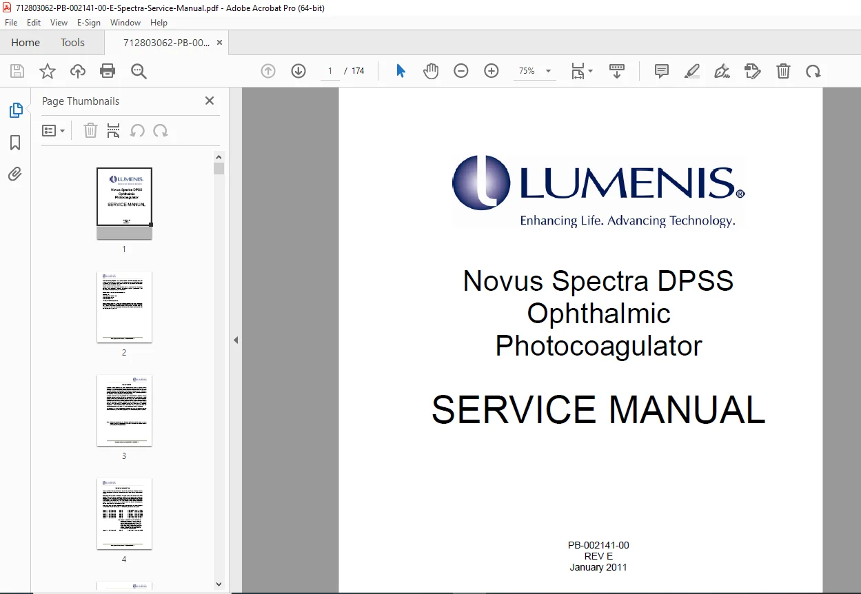
Lumenis Novus Spectra Service Manual PDF DOWNLOAD
Original price was: $95.00.$18.95Current price is: $18.95.
Official Lumenis Novus Spectra service manual PDF for the DPSS ophthalmic photocoagulator, covering general info, installation, alignment, theory, troubleshooting, parts, and schematics. Includes Novus Spectra DPSS alignment procedures, Lumenis ophthalmic photocoagulator troubleshooting, Novus Spectra calibration guide, Lumenis Novus Spectra theory of operation, and Novus Spectra parts list with safety precautions and diagrams. 174 pages for certified technicians.
Description
Lumenis Novus Spectra Service Manual PDF DOWNLOAD
Description
This official Lumenis Novus Spectra service manual PDF (PB-002141-00 REV E, January 2011) from Lumenis, Inc. is a restricted guide for certified service engineers and technicians maintaining the Novus Spectra DPSS ophthalmic photocoagulator. It provides detailed instructions on system use, safety, installation, calibration, operation theory, fault isolation, and part replacements, emphasizing compliance with FDA regulations and prohibiting unauthorized repairs. The manual includes warnings on optical, electrical, and fire hazards, with references to operator manuals for delivery systems like slit lamps, LaserLink Z, and LIO. Key features cover Novus Spectra DPSS alignment procedures for resonator and output delivery, Lumenis ophthalmic photocoagulator troubleshooting via error codes and test points, Novus Spectra calibration guide for power and accessories, and Lumenis Novus Spectra theory of operation detailing control electronics, optical components, and software modes.
Structured for practical servicing, it supports tasks like site preparation, console installation, periodic maintenance, and schematic analysis. No separate index is present, but Section 7 incorporates Field Service Bulletins (FSBs) and Technical Notes (TNs) via an updatable index.
- Table of Contents (Neatly categorized from pages 5-8):
| Section | Title | Page |
|---|---|---|
| 1.0 | General Information | 1-1 |
| 1.1 | Use of this Manual | 1-1 |
| 1.2 | Conventions Used in this Manual | 1-1 |
| 1.3 | Serial Number Format | 1-2 |
| 1.4 | Certification of Compliance and Approvals | 1-2 |
| 1.5 | Service Information and FDA Compliance | 1-3 |
| 1.6 | Safety Precautions | 1-5 |
| 1.6.1 | System Safety Measures | 1-6 |
| 1.6.2 | Optical Safety | 1-6 |
| 1.6.3 | Eye Protection | 1-7 |
| 1.6.4 | Fire Hazards | 1-7 |
| 1.6.5 | Treatment Room | 1-8 |
| 1.6.6 | Electrical and Mechanical Safety | 1-8 |
| 1.7 | System Specifications | 1-9 |
| 2.0 | Installation Information | 2-1 |
| 2.1 | Introduction | 2-1 |
| 2.2 | Site Preparation and Inspection | 2-1 |
| 2.3 | Unpack System | 2-2 |
| 2.4 | Novus Spectra Console Installation Procedure | 2-3 |
| 2.5 | Slit Lamp Installation Procedure | 2-6 |
| 2.6 | LaserLink Z Installation Procedure | 2-6 |
| 2.7 | Laser Indirect Ophthalmoscope (LIO) Installation Procedure | 2-7 |
| 2.8 | Remote Interlock Switch Installation Procedure | 2-7 |
| 2.9 | Operational and Safety Checkout | 2-8 |
| 2.10 | Periodic Maintenance | 2-13 |
| 3.0 | Alignment, Adjustment and Calibration | 3-1 |
| 3.1 | Overview | 3-1 |
| 3.1.1 | Procedure List | 3-1 |
| 3.1.2 | TEST EQUIPMENT REQUIRED | 3-2 |
| 3.2 | Resonator (Laser) Plate Alignment | 3-2 |
| 3.3 | Output Delivery (Aiming Beam) Alignment | 3-2 |
| 3.3.1 | Purpose and Scope | 3-2 |
| 3.3.2 | Procedure | 3-3 |
| 3.3.2.1 | Aiming Beam Collimation | 3-3 |
| 3.3.2.2 | Aiming Beam Alignment | 3-5 |
| 3.4 | Electrical Adjustments | 3-5 |
| 3.5 | Mechanical Adjustments | 3-6 |
| 3.5.1 | Optical Delivery Alignment | 3-6 |
| 3.6 | Power Calibration | 3-6 |
| 3.6.1 | Required Equipment/Tools | 3-6 |
| 3.6.2 | Prerequisites | 3-6 |
| 3.6.3 | Calibration Procedure | 3-7 |
| 3.6.3.1 | Eye Safety Filter Test | 3-8 |
| 3.6.3.2 | Footswitch Test | 3-8 |
| 3.6.3.3 | Illumination Accessory Test | 3-9 |
| 3.6.3.4 | Remote Control Test | 3-9 |
| 4.0 | Theory of Operation | 4-1 |
| 4.1 | Introduction | 4-1 |
| 4.1.1 | Main Console | 4-1 |
| 4.1.2 | Delivery Systems | 4-2 |
| 4.1.3 | Physician Filter (Eye Safety Filter) | 4-2 |
| 4.1.4 | Footswitch | 4-2 |
| 4.2 | Power Switching, Conditioning & Distribution | 4-3 |
| 4.2.1 | Main Input Power | 4-3 |
| 4.2.2 | Power Distribution | 4-3 |
| 4.2.2.1 | AC to DC Power Supply Module | 4-3 |
| 4.2.2.2 | Low Voltage Monitor | 4-3 |
| 4.2.2.3 | 48 Volt Interlock | 4-5 |
| 4.2.2.4 | CPU Board | 4-5 |
| 4.3 | Temperature Control Systems | 4-5 |
| 4.3.1 | DC Fans | 4-5 |
| 4.3.2 | Heater/Cooler PCB | 4-6 |
| 4.3.2.1 | Power Supply Interface | 4-6 |
| 4.3.2.2 | Digital Interface | 4-7 |
| 4.3.2.3 | Analog Interface | 4-7 |
| 4.3.2.4 | TEC Failure Detect Circuit | 4-7 |
| 4.3.3 | KTP Heater | 4-8 |
| 4.4 | Control Electronics | 4-9 |
| 4.4.1 | Overview | 4-9 |
| 4.4.2 | The Stack | 4-9 |
| 4.4.3 | Analog I/O | 4-9 |
| 4.4.3.1 | Power Supply Interface | 4-9 |
| 4.4.3.2 | System Bus Interface | 4-10 |
| 4.4.3.3 | Analog to Digital | 4-10 |
| 4.4.3.4 | Digital to Analog | 4-10 |
| 4.4.4 | Digital I/O | 4-11 |
| 4.4.4.1 | Main Circuit Description | 4-11 |
| 4.4.4.2 | Power | 4-12 |
| 4.4.5 | CPU Board | 4-12 |
| 4.4.5.1 | Circuit Description | 4-12 |
| 4.4.5.2 | Power | 4-14 |
| 4.4.6 | Auxiliary Interface Board | 4-14 |
| 4.4.7 | Diode Drive Control | 4-15 |
| 4.4.7.1 | Digital Interface | 4-15 |
| 4.4.7.2 | Analog Interface | 4-15 |
| 4.4.8 | Diode Drive Base | 4-15 |
| 4.4.8.1 | Diode Power Supply | 4-15 |
| 4.4.8.2 | Digital Interface | 4-16 |
| 4.4.8.3 | Analog Interface | 4-16 |
| 4.4.9 | Main and Safe Light Feedback | 4-16 |
| 4.4.10 | Interfaces | 4-18 |
| 4.4.10.1 | Head Interface | 4-18 |
| Diode Thermistor Interface | 4-18 | |
| KTP Heater Interface | 4-19 | |
| 4.4.10.2 | Remote/Footswitch Interface | 4-19 |
| Digital I/O Interface | 4-19 | |
| CPU Interface | 4-20 | |
| Auxiliary Power Supply Interface | 4-20 | |
| 4.4.10.3 | Optical Delivery Interface | 4-20 |
| Safety Shutter Interface | 4-20 | |
| Analog Interface | 4-20 | |
| 4.4.10.4 | Accessory Interface | 4-21 |
| Solenoid Driver | 4-22 | |
| Motor Driver | 4-22 | |
| Resistor Sense | 4-23 | |
| Auxiliary Power Supply Interface | 4-23 | |
| 4.4.11 | Front Panel | 4-24 |
| 4.5 | Optical Components | 4-25 |
| 4.5.1 | Optical Description | 4-26 |
| 4.6 | Software (User and Service Mode Software) | 4-29 |
| 4.6.1 | Overview | 4-29 |
| 4.6.2 | Safety Monitoring | 4-30 |
| 4.6.3 | User Mode Routines (System Start-up, Standby, and Treatment) | 4-30 |
| 4.6.3.1 | Start-up (Initialization and Self-test) State | 4-30 |
| 4.6.3.2 | Standby State | 4-31 |
| 4.6.3.3 | Ready State | 4-31 |
| 4.6.3.4 | Treatment (Fire) State | 4-32 |
| 4.6.3.5 | Warning State | 4-32 |
| 4.6.3.6 | Shutdown State | 4-33 |
| 5.0 | Troubleshooting | 5-1 |
| 5.1 | Overview | 5-1 |
| 5.2 | Interior Access and Part Location | 5-2 |
| 5.2.1 | Top Cover Removal | 5-2 |
| 5.2.2 | Bottom Cover Removal | 5-3 |
| 5.2.3 | Front Panel Removal | 5-3 |
| 5.3 | Error Codes and Fault Isolation | 5-5 |
| 5.4 | Test Point, Connector and LED Arrangement | 5-11 |
| 5.4.1 | Coldfire CPU Board | 5-11 |
| 5.4.2 | Optical Delivery Interface | 5-13 |
| 5.4.3 | Digital I/O Board | 5-14 |
| 5.4.4 | Analog I/O Board | 5-15 |
| 5.4.5 | Head Interface Board | 5-19 |
| 5.4.6 | Diode Drive Base Board | 5-19 |
| 5.4.7 | 48 Volt Interlock Board | 5-20 |
| 5.4.8 | 48 Volt Interlock Adapter | 5-21 |
| 5.4.9 | Low Voltage Monitor Board | 5-22 |
| 5.4.10 | Front Panel Board | 5-23 |
| 5.4.11 | KTP Heater/Cooler Board | 5-24 |
| 5.4.12 | TEC Heater/Cooler Board | 5-25 |
| 5.4.13 | Digital I/O Harness Adapter Board | 5-26 |
| 5.4.14 | Analog I/O Harness Adapter Board | 5-27 |
| 5.4.15 | Diode Drive Control Board | 5-28 |
| 5.4.16 | Current Monitor Board | 5-29 |
| 5.4.17 | Aux Power Supply Board | 5-30 |
| 5.4.18 | Aux Interface Board | 5-31 |
| 6.0 | Selected Part Numbers | 6-1 |
| 6.1 | Service Tools | 6-1 |
| 6.2 | User Replaceable Sub-Assemblies | 6-1 |
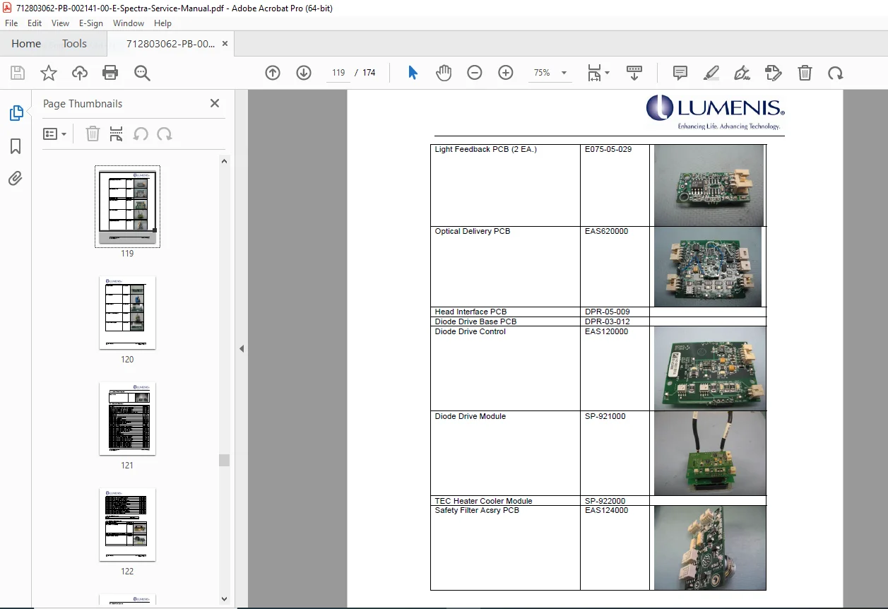
| 6.3 | System Circuit Boards | 6-1 |
| 6.4 | Laser Power Supply | 6-2 |
| 6.5 | Chassis Electrical | 6-2 |
| 6.6 | Cooling System | 6-3 |
| 6.7 | Optical Components | 6-3 |
| 6.8 | Covers & Skins | 6-3 |
| 6.9 | MISC. Parts | 6-3 |
| 6.10 | Delivery Systems | 6-4 |
| 7.0 | Field Service Bulletins and Technical Notes | 7-1 |
| 7.1 | Introduction | 7-1 |
| 7.2 | Index | 7-1 |
| 8.0 | Drawings and Schematics | 8-1 |
- List of Schematics (From Section 8.0):
| Schematic Name | Pages |
|---|---|
| Novus Spectra Simplified Block Diagram | 1 |
| Novus Spectra Laser System Wiring Diagram | 1 |
| Optical Schematic | 1 |
| Coldfire (CPU) Board | 6 |
| Optical Delivery Interface | 1 |
| Digital I/O Board | 5 |
| Analog I/O Board | 3 |
| Head Interface | 1 |
| Diode Drive Base | 1 |
| 48 Volt Interlock | 1 |
| 48 Volt Interlock Adaptor | 1 |
| Low Voltage Monitor | 1 |
| Front Panel Board | 2 |
| KTP Heater | 1 |
| Digital I/O Harness Adapter | 1 |
| Analog I/O Harness Adapter | 1 |
| TEC Heater/Cooler | 1 |
| Diode Drive Control | 1 |
| Current Monitor | 1 |
| Safety Filter Accessory Interface | 2 |
| Aux Power Supply +5V, +12V | 2 |
| Aux Interface | 1 |
| Remote/Footswitch Interface | 1 |
| Light Feedback | 1 |
| Optical Delivery I/O Dual Port | 1 |
| Port Selector Dual Port | 1 |
Essential for Lumenis ophthalmic photocoagulator troubleshooting, Novus Spectra calibration guide procedures, and system repairs using genuine parts. Specifications subject to change; verify with Lumenis
File Details
- Manual Name: Novus Spectra DPSS Ophthalmic Photocoagulator Service Manual
- Models Covered: Novus Spectra
- Year: 2011
- Manual PDF Quality: High quality with clear text, tables, diagrams, and schematics
- No. of Pages: 174