
MacGregor GL-2 Deck Crane Instruction & Parts Manual – GL 6019/5022/4524/4027/3630-2 (LO04062)
Original price was: $71.95.$44.95Current price is: $44.95.
Complete MacGREGOR GL-2 hydraulic deck crane instruction and parts manual for GL 6019/5022/4524/4027/3630-2, covering operation, maintenance, service, troubleshooting and exploded-view spare parts. 517-page PDF.
Description
File Details
- Manual type: Instruction and Parts Manual — operation, maintenance, service, troubleshooting and spare parts for the MacGREGOR GL-2 hydraulic deck crane
- Brand: MacGREGOR
- Crane type: GL 6019/5022/4524/4027/3630-2 (GL-2 series)
- Language: English, with a German hydraulic and electric symbol glossary
- Manual No.: 11139
- Project No.: LO04062
- Mfg. No.: 62506198 — Crane 1
- Vessel: KIRIBATI CHIEF (IMO No. L8809189, Newbuilding No. 1348, Wenchong SY, Owners CNCO)
- Order specification: 490 4637-801/F (crane), 490 4643-801/D (EI.)
- Page count: 517
- File format: PDF
Chapters Covered
The MacGregor GL-2 deck crane manual is arranged in nine sections that mirror the printed instruction and parts manual:
- 1. General
- 2. Technical Description
- 3. Function
- 4. Operation
- 5. Maintenance
- 6. Service
- 7. Extra Equipment
- 8. Appendices
- 9. Spare Parts
1. General
Safety instructions for the cargo handling equipment, the preface, and the general cleanliness rules for working on hydraulic systems. Also includes conversion factors and a bilingual hydraulic and electric symbol key covering working oil lines, pilot lines, drain lines, filters with and without by-pass, pumps, motors, direction valves, pressure limiting valves, pressure switches, accumulators, and electric circuit symbols (relays, contacts, limit switches, thermostats, encoders, and more).
2. Technical Description
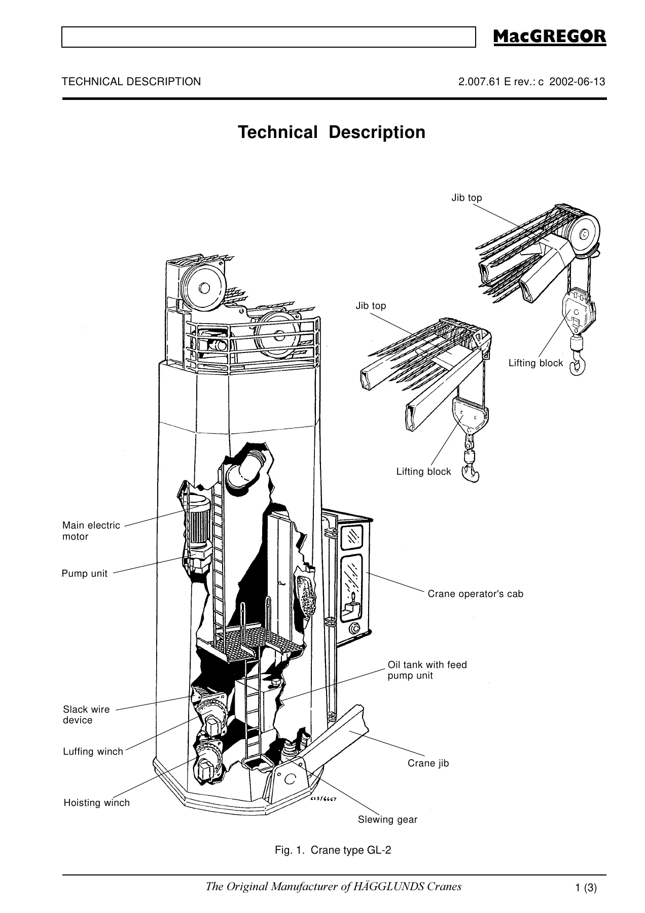
Technical data for the main electric motor, off-line oil filtration motor, feed and control circuit motor, feed pump, hoisting and luffing wire ropes, oil tank and planetary gear box volumes. The technical description section then explains the crane’s construction, hoisting winch, luffing winch, slewing drive, feed pump, oil cooler, cab and jib, electric equipment, hydraulic hoses, surface treatment and twin-crane configuration.
3. Function
The hydraulic function of the hoisting, luffing and slewing circuits, including feed and control pressure circuits, contamination switches, off-line filtration, and pressure-test points. Covers starting and stopping sequences for single cranes, electric safety functions, the CC2000 crane control system with Auto Loadstep and Multi SWL plussing, and thermostatic ventilation fan control.
4. Operation
The crew checklist, start and stop procedure, emergency stop, siren use, control levers, list and trim limits, dragging-load warnings, cabin control panel, warning lights and indicators, emergency escape by rope and ladder, parking and sea stowing, and safe handling of hatches with a deck crane.
5. Maintenance
The maintenance chart with intervals from daily checks to ten-year hose replacement, inspection of stressed components and structures, contamination switch and chip detector, automatic lubrication of the slewing bearing, lubricants for deck machinery, filters, hydraulic oil tank, oil sampling, extra off-line filtration, and the lubricating and maintenance photo guide covering doors, electric motor, slewing bearing, jib bearing, wire sheaves, wire rope sockets, slewing gear case, lifting equipment, oil tank, oil filter, wire ropes, parking cylinders, cable winch and power swivel.
6. Service
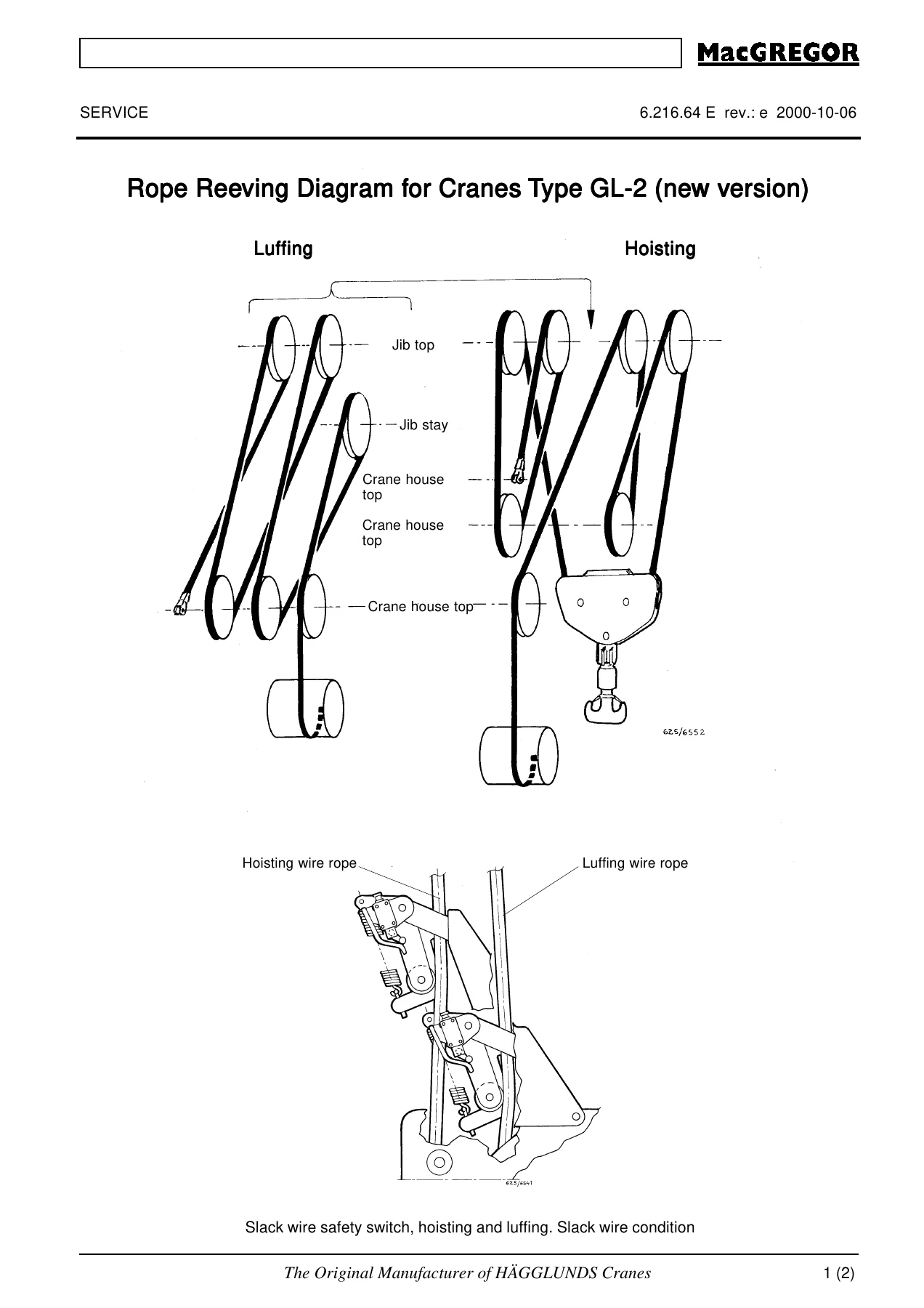
How to order spare parts, global service contacts, measures before starting service work, and the full troubleshooting and repair sections for the hydraulic system, mechanical equipment and electrical equipment. Topics include overheating, pumps, slewing gearset, hydraulic motors, winches, high-pressure pumps, hydraulic accumulators, tightening torques, rope reeving, wire rope handling and replacement, lifting block, slewing bearing wear, emergency operation card, CC2000 electronic troubleshooting, signal overview, error messages, contamination LEDs, electrical general maintenance, slip-ring unit, oil level float switch, limit switches, slack wire switch, and emergency lowering with a hand pump.
7–8. Extra Equipment and Appendices
Extra equipment supplied on request and appendices for any information not covered by the main sections.
9. Spare Parts
Parts manual with exploded-view figures and article numbers covering the hoisting winch, luffing winch, slewing gear, slewing bearing, pump unit, gear box, hydraulic pumps A4VG 125, feed pump unit, oil cooler, oil tank assembly, crane house, jib, jib bearing, limit switch boxes, slack wire device, cab, emergency door, ventilation fan, lifting block, valve units, direction valves, filter units, flush and unloading units, hydraulic hoses, accumulators, power supply, driver’s desk, controllers, control panel, slip-ring unit, angle encoders, lubrication system, grease pump, grease refilling pump, fire extinguisher mount, and the accessory electrical components.
Technical Data You Will Find in This Manual
The technical data section records the primary drive values for the GL-2: the main electric motor is rated 184 kW continuous / 290 kW at S6 40% intermittent duty, 1788 rev/min, 440 V, with a starting current of 710 A. The off-line oil filtration motor is a 1.5 kW, 1700 rev/min, 230 V unit. The feed and control circuit motor is rated 20 kW at 2-pole and 13 kW at 4-pole, driving a 49.1 cm³/rev feed pump submerged in the tank. The hoisting wire rope is 38 mm × 287.5 m (article 390 3922-821), and the luffing wire rope is 32 mm × 187.5 m (article 390 4274-815). The hydraulic oil tank holds 560 litres; each of the three planetary gear boxes holds 15.5 litres; the hoisting winch gear takes 39.0 litres; and the luffing winch gear takes 10.5 litres.
Three Hydraulic Work Circuits and the CC2000 Control System
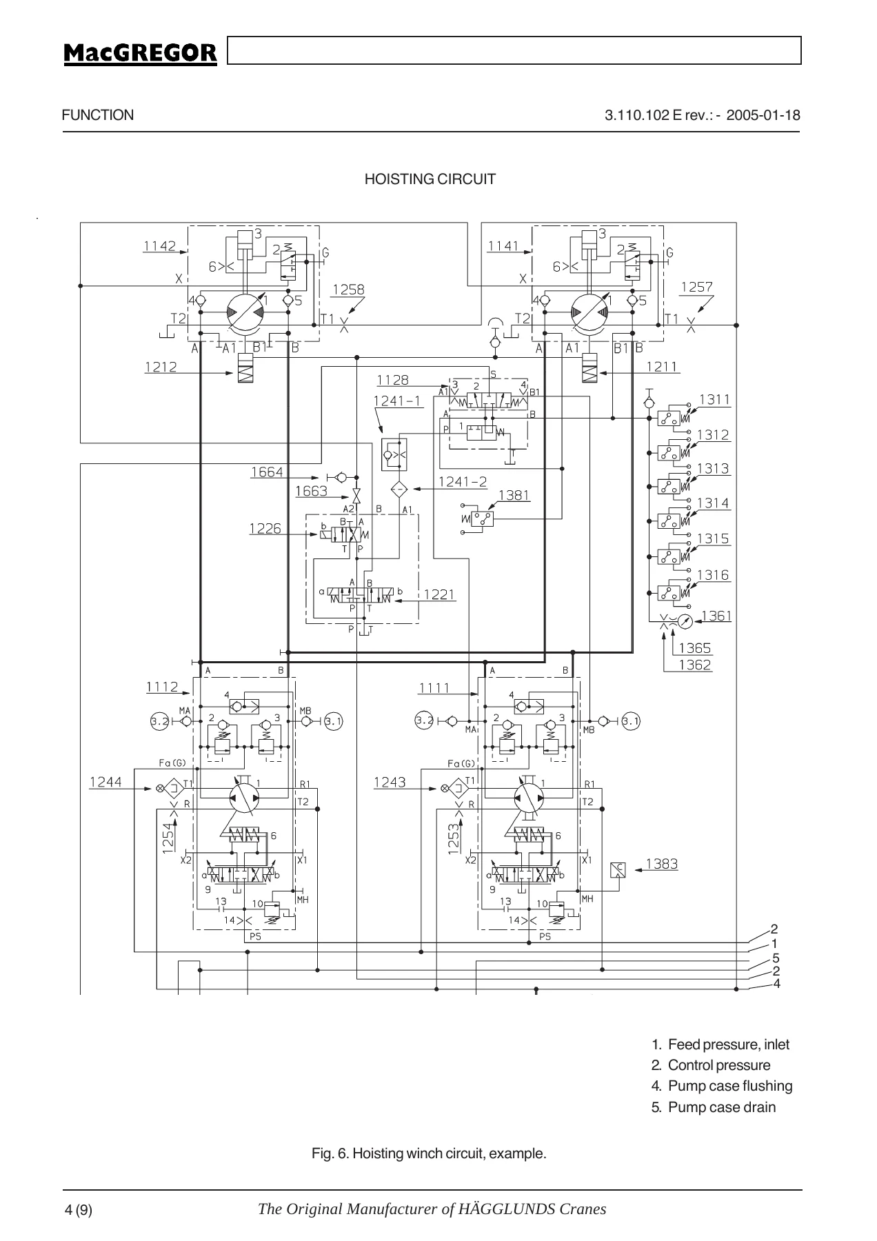
Every GL-2 crane runs three separate hydraulic work circuits — hoisting, luffing and slewing — plus a shared feed and control-pressure circuit. The MacGregor GL-2 manual documents each in full: the variable-displacement pumps (1111, 1112, 2111, 3111), the hydraulic motors (1141, 2141, 3141, 3142, 3143), the multiple-disc and band brakes, the pressure limiting valves, the pressure cut-off valves, and the contamination switches mounted on the pump housings. The feed circuit runs at approximately 2.5 MPa (25 bar) and the control circuit at 3.0–3.3 MPa (30–33 bar), with exact values listed in the pressure setting list on the hydraulic circuit diagrams.
The CC2000 control system is covered in full, including the MPC micro-processor cards (Sc, Ho, Lu, SL), the parameter memory card, the joystick potentiometers, the PWM pump solenoid outputs, the Auto Loadstep overload logic with interlocking cams on the luffing limit switch box, the speed-dependent overload function, the hoisting speed encoder, and the built-in diagnostics accessed through the error LED and STEP push-button on each card. This is the same control architecture used in the twin-crane and multi-outreach variants, and the manual explains the interfaces between the control cabinet and the hydraulic valves, brakes and sensors.
Safety Signage, Warning Labels and Emergency Procedures
The manual reproduces every danger, warning, caution and notice sign fitted to the GL-2 deck crane, each with its PM40 reference number — from PM40 7101-E00 (Report to Superintendent or Operator’s Room for Permit to Enter) and PM40 7102-E00 (Do Not Enter During Crane Operation) through to PM40 7142-E00 (High Voltage Inside, Do Not Open). The illustrations show how to recognise the warning-ladder rotation, hot oil surfaces, suspended load, slipping surfaces, spring tension, rotating fan, high voltage and hydraulic pressure hazards, and how to keep the safety chains, safety belt, rescue line and fire extinguisher in service.
Emergency procedures are also documented in depth: escape from the crane operator’s cabin using the escape line and safety belt, escape using the rope ladder or fixed ladders, emergency lowering of the load using the hand pump and the by-pass line, and emergency slewing with the same equipment. Each procedure includes the connection points, valve numbers and precautions printed in the original manual.
Why the MacGregor GL-2 Deck Crane Instruction and Parts Manual Matters
This is not a generic crane book. It is the exact instruction and parts manual prepared for the GL-2 series under Project No. LO04062 and Manual No. 11139, and it carries the same document references, article numbers and technical values that were delivered with the crane. For the chief engineer, the deck officer, the shoreside workshop or the fleet superintendent, it is the reference that lets you plan a correct repair rather than a guess, order the right part the first time, and set the pressure and torque values back to the values MacGREGOR specified.
Use the troubleshooting chapters to trace a fault in the hoisting, luffing or slewing circuit — high pressure, low feed pressure, motor not running, brake not releasing, slewing gear backlash, wire rope slack, limit switch out of position, contamination alarm, or a CC2000 error message — and use the service sections to replace the wire rope, recharge the accumulator, reseal the motor brake, set the limit switches, replace the hydraulic hoses, adjust the pump servo or overhaul the feed pump unit. Each procedure gives the sequence, the tools and the numbers needed to do the job safely.
IMAGES PREVIEW
Delivery is instant: the PDF is available for download immediately after payment, with no shipping, no waiting for the post, and no separate courier charge. The same file opens on a Windows or Mac computer, a tablet or a phone, and is fully printable for the workshop or the engine room. Keep a copy on the bridge, one in the workshop, and one on the office server — no need to hunt down a single paper copy that has to travel with the ship.
Reviews
There are no reviews yet.