
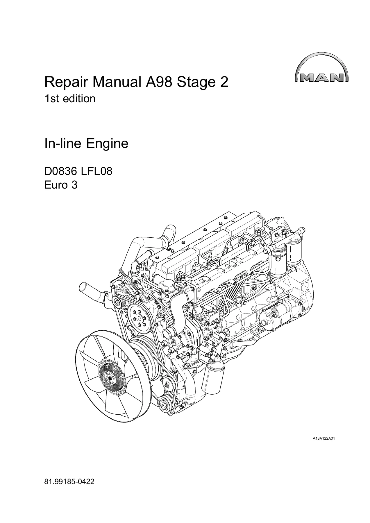
MAN D0836 LFL08 Euro 3 Diesel Engine Repair Manual A98 Stage 2 – PDF Download
Original price was: $47.95.$27.95Current price is: $27.95.
Complete 276-page MAN repair manual for the D0836 LFL08 Euro 3 in-line six-cylinder diesel engine – document 81.99185-0422, 1st edition. Covers cooling, fuel, charging, cylinder head, valve timing, lubrication, crank mechanism and engine housing with torque values and step-by-step procedures.
Description
MAN D0836 LFL08 Euro 3 Repair Manual – A98 Stage 2
This is the full MAN D0836 LFL08 Euro 3 diesel engine repair manual, issued as A98 Stage 2 under document number 81.99185-0422. It is the 1st edition workshop documentation for the in-line, six-cylinder D0836 LFL08 engine fitted with the VP44 injection pump, and it walks a technician through every major repair group on the unit – from removing the fan and coolant pump through to stripping the crank mechanism. If you work on this engine, this is the reference that tells you the sequence, the torque figure and the tool.
File Details
- Manual type: Repair Manual (Reparaturanleitung)
- Brand: MAN
- Model: D0836 LFL08
- Engine: D0836 LFL08 Euro 3, 6-cylinder in-line diesel
- Language: English
- Page count: 276
- File format: PDF
- Document number: 81.99185-0422
- Edition: 1st edition
- Publisher: MAN Truck & Bus AG
Chapters Covered
- Introduction
- Cooling system
- Add-on units
- Fuel system
- Charging
- Charge-air pipe/exhaust system
- Cylinder head
- Valve timing
- Engine lubrication
- Crank mechanism
- Engine housing
- Power take-off
Introduction
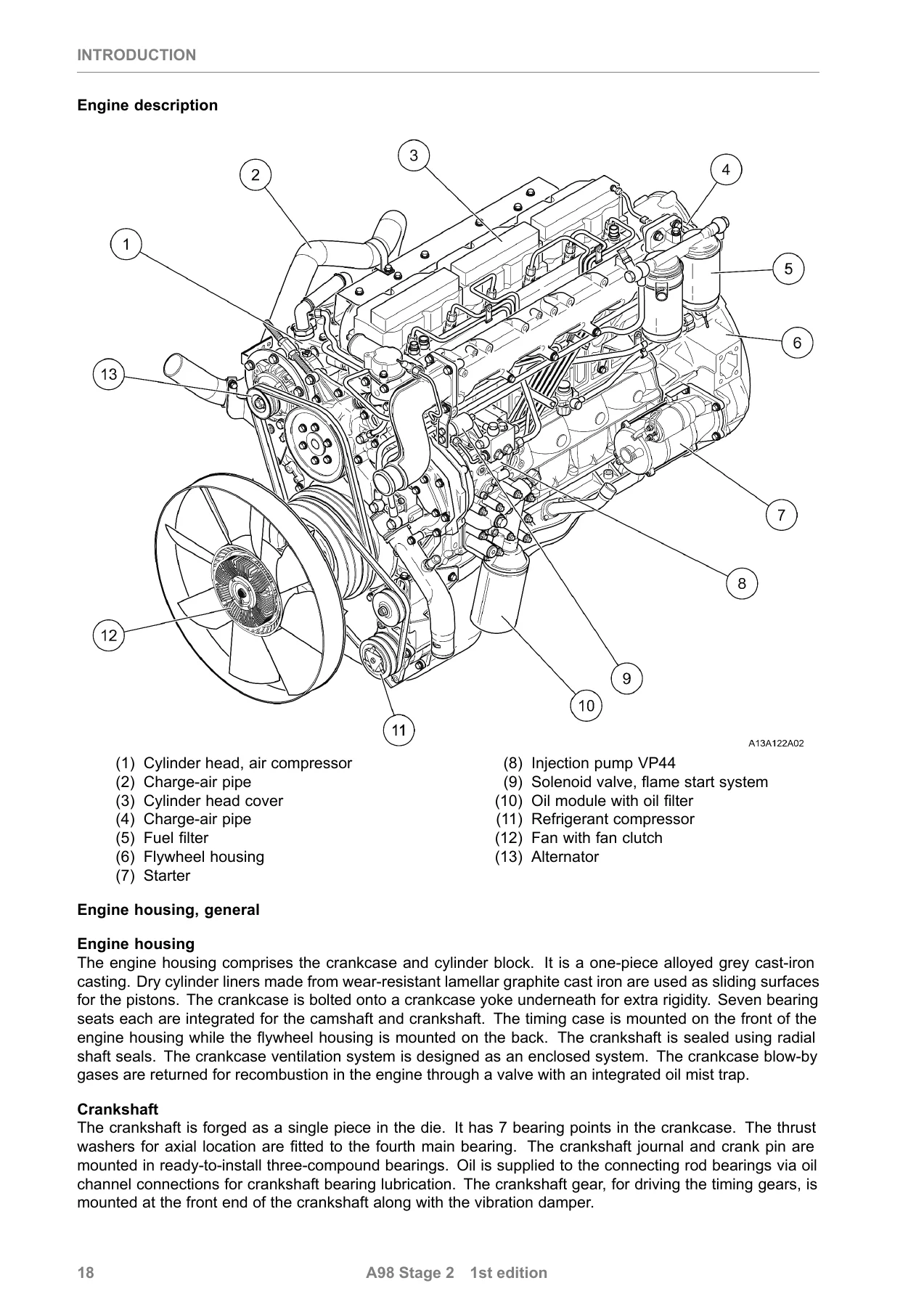
The opening section sets out the safety instructions for working on the D0836 LFL08, including the handling rules for the fuel high-pressure side, battery and electrical work, welding precautions, air-conditioning and airbag systems. It then documents the engine itself – the model plate and designation, characteristic data and a system-by-system engine description covering the crankcase, crankshaft, cracked connecting rods, three-ring pistons, camshaft, forced-feed lubrication, thermostatically controlled cooling circuit and the VP44 injection system.
Cooling System
Fan removal and installation with the viscous fan clutch (and the warning to store the clutch standing up), coolant pipe and distributor pipe procedures, thermostat removal and installation with the 83 °C opening temperature and the thermostat housing, plus coolant pump removal, installation and a full strip-and-rebuild of the pump – including bearing, circlip, slide ring seal and impeller handling with the 0.4 mm impeller-to-housing gap.
Add-on Units
This group covers the 1-cylinder air compressor and power steering pump, the pre-engaged starter (12-tooth pinion, 4 kW at 24 V), the alternator with its multifunction controller, the complete belt drive with V-belt tensioning forces, and the refrigerant compressor. Removal and installation sequences, mounting torques and the relevant special tools are listed for each unit.
Fuel System
Injector nozzle removal and installation, including the ball-mark alignment rule and the pressure screw torque, the VP44 injection pump removal, installation and start-of-delivery setting with the dial gauge, the low-pressure system with fuel filter, fuel filter heater and hand pump, and the flame start system with the flame glow plug and solenoid valve.
Charging, Charge-Air Pipe and Exhaust System
Turbocharger removal and installation with the wastegate valve data, oil feed and return line handling, and the intake fitting. The exhaust manifold section covers the two-piece manifold, the stretch-bolt rule (manifold bolts must not be re-used) and the heat shield, while the charge-air pipe chapter documents the charge-air manifold, charge-air pipe and charge-pressure sensor.
Cylinder Head
The rocker arm mechanism chapter (variant with EVB) covers dismantling and assembly of the rocker arm shaft, brackets, pressure springs and circlips. Cylinder head removal and installation includes the tightening diagram and the staged cylinder head bolt procedure, dismantling and assembly of the head with valve springs, valve stem seals and valve cotters, the valve setback tolerances and the complete valve clearance setting procedure – including forcing oil out of the EVB piston and the 0.35 mm EVB piston clearance.
Valve Timing
Camshaft and camshaft bearing removal and installation with the bearing press-in and press-out sequences, timing gear removal and installation covering the crankshaft gear, camshaft gear, intermediate gears and oil pump drive gear with their backlash values, timing case removal and installation, and front crankshaft oil seal removal and installation with the PTFE sealing ring handling rules.
Engine Lubrication
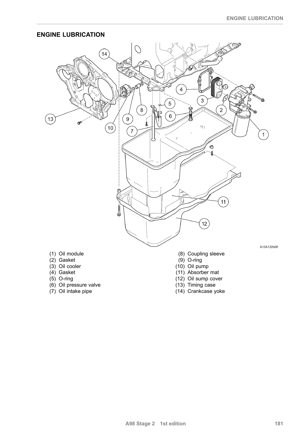
The oil module with oil cooler, oil pressure switch and oil filter, oil sump removal and installation with the oil intake pipe and oil excess pressure valve, oil pump removal, installation, strip and assembly with the axial play check, and oil injector nozzle removal and installation with the oil pressure valve opening pressures.
Crank Mechanism
Vibration damper removal and installation (stretch bolts, must not be re-used), flywheel removal and installation with lateral runout limits and ring gear replacement, pistons and connecting rods with piston pin, ring gap and connecting rod bearing checks, and crankshaft removal and installation with axial and radial play measurement, journal dimensions and repair levels.
Engine Housing and Power Take-Off
Cylinder liner removal and installation with standout check, flywheel housing with power take-off including the intermediate gears and crankshaft gear, rear crankshaft oil seal, crankcase yoke, crankcase ventilation with the oil separator and pressure control valve, and finally the power take-off unit itself.
Why This MAN D0836 LFL08 Repair Manual Matters
Commercial diesel engines are unforgiving of guesswork. The D0836 LFL08 runs high cylinder pressures through a VP44 pump, stretch-bolt cylinder head and manifold fasteners, and a cracked connecting rod design that punishes careless handling. Torque figures here are not suggestions – they are staged angle-tightening sequences, and the manual tells you exactly which bolts are single-use, which clearances must be measured with a dial gauge, and which components must be aligned to a mark before assembly. Working without this document means risking a distorted cylinder head, a slipped injection pump timing, or a bearing clearance out of specification.
What You Can Do With It
Use it to service the cooling circuit, replace the thermostat, rebuild the coolant pump, set valve clearance, strip and rebuild the cylinder head, replace timing gears, remove and refit the injection pump and set start of delivery, overhaul the turbocharger, replace pistons, connecting rods and crankshaft bearings, replace cylinder liners and both crankshaft oil seals, and service the crankcase ventilation. Because the manual lists the special tools and the measurement values at each step, it supports both routine maintenance and a full engine overhaul.
IMAGES PREVIEW
Instant PDF Delivery
The manual is supplied as a PDF download – no shipping, no waiting, no physical book to lose in the workshop. Open it on a laptop, tablet or phone at the machine, print the pages you need for the job in front of you, and keep the rest clean. Every torque value, tightening diagram, clearance figure and procedure for the D0836 LFL08 is one search away.
Reviews
There are no reviews yet.