
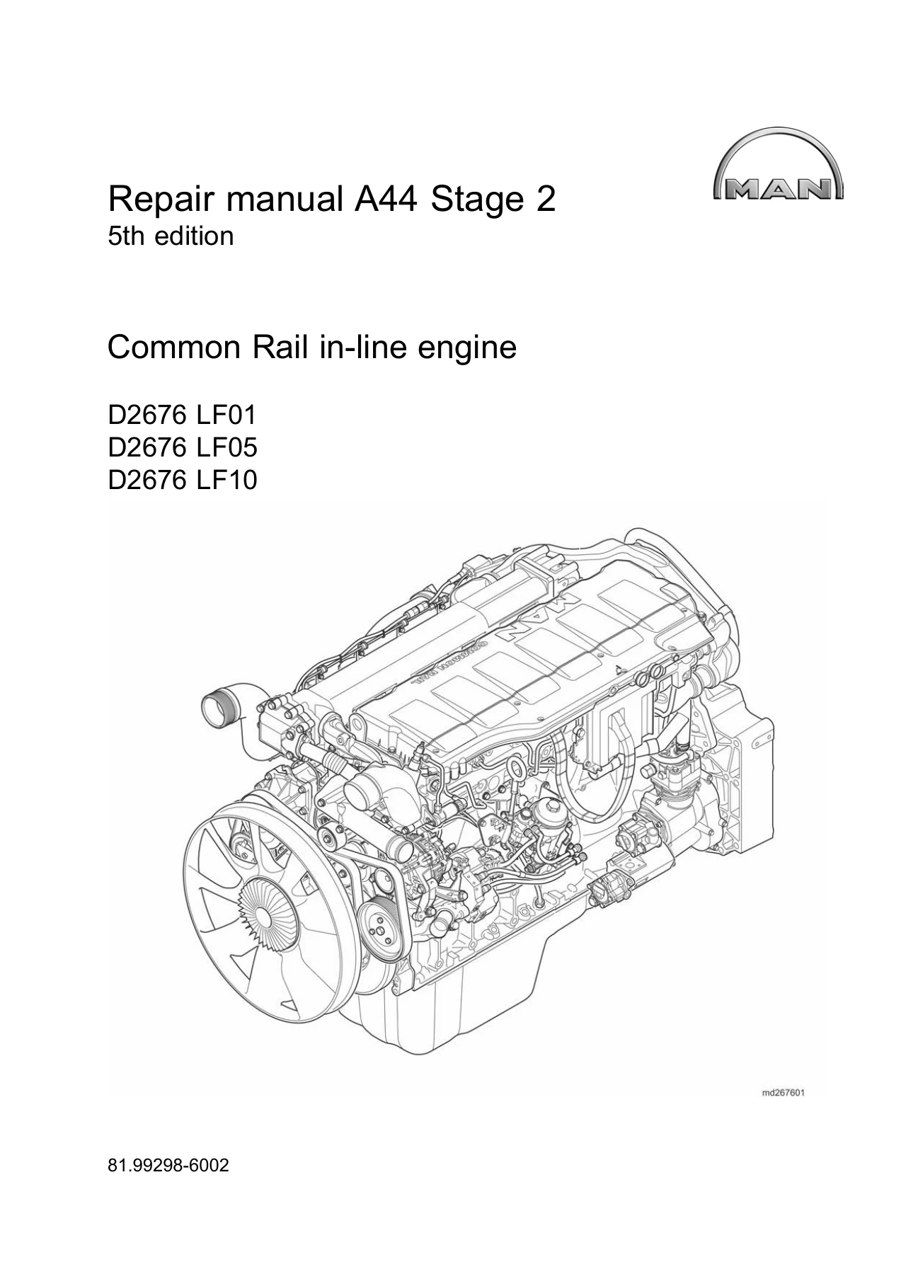
MAN D2676 LF01 LF05 LF10 Common Rail Engine Repair Manual – 5th Edition PDF Workshop Guide
Original price was: $59.95.$39.95Current price is: $39.95.
Complete 5th edition repair manual for the MAN D2676 LF01, LF05 and LF10 Common Rail in-line diesel engines. Covers injectors, high-pressure pump, cylinder head, timing gears, crankshaft, EDC electronics and full technical data. Instant PDF download.
Description
MAN D2676 LF01, LF05, LF10 Common Rail Repair Manual – 5th Edition
This is the complete MAN D2676 LF01 / LF05 / LF10 Common Rail in-line engine repair manual, 5th edition. It is the same comprehensive workshop document used by professional technicians to service, diagnose and overhaul the 6-cylinder Euro 4 diesel engine found in MAN truck and bus applications. Whether you are replacing injectors, setting valve clearance, extracting a stubborn high-pressure pump or checking crankshaft bearing clearances, this manual gives you the exact procedures, torque values and diagnostic guidance you need.
File Details
- Manual type: Repair Manual
- Brand: MAN Truck & Bus AG
- Models covered: D2676 LF01, D2676 LF05, D2676 LF10
- Engine type: 6-cylinder in-line, 4-stroke, Common Rail diesel with turbocharging
- Language: English
- Page count: Approximately 495 pages
- File format: PDF
- Document number: 8199298-6002
- Edition: 5th edition
- Date: 07.2015
Chapters Covered
- Introduction
- Engine electronics
- Cooling system
- Add-on units
- Common-Rail-system
- Turbocharging
- Intake/exhaust system
- Cylinder head
- Valve control
- Timing gears and drive wheels
- Engine lubrication
- Crankshaft seals
- Crank drive
- Engine housing
- PTO (Power take-offs)
- Engine brake system
- Technical Data
Introduction
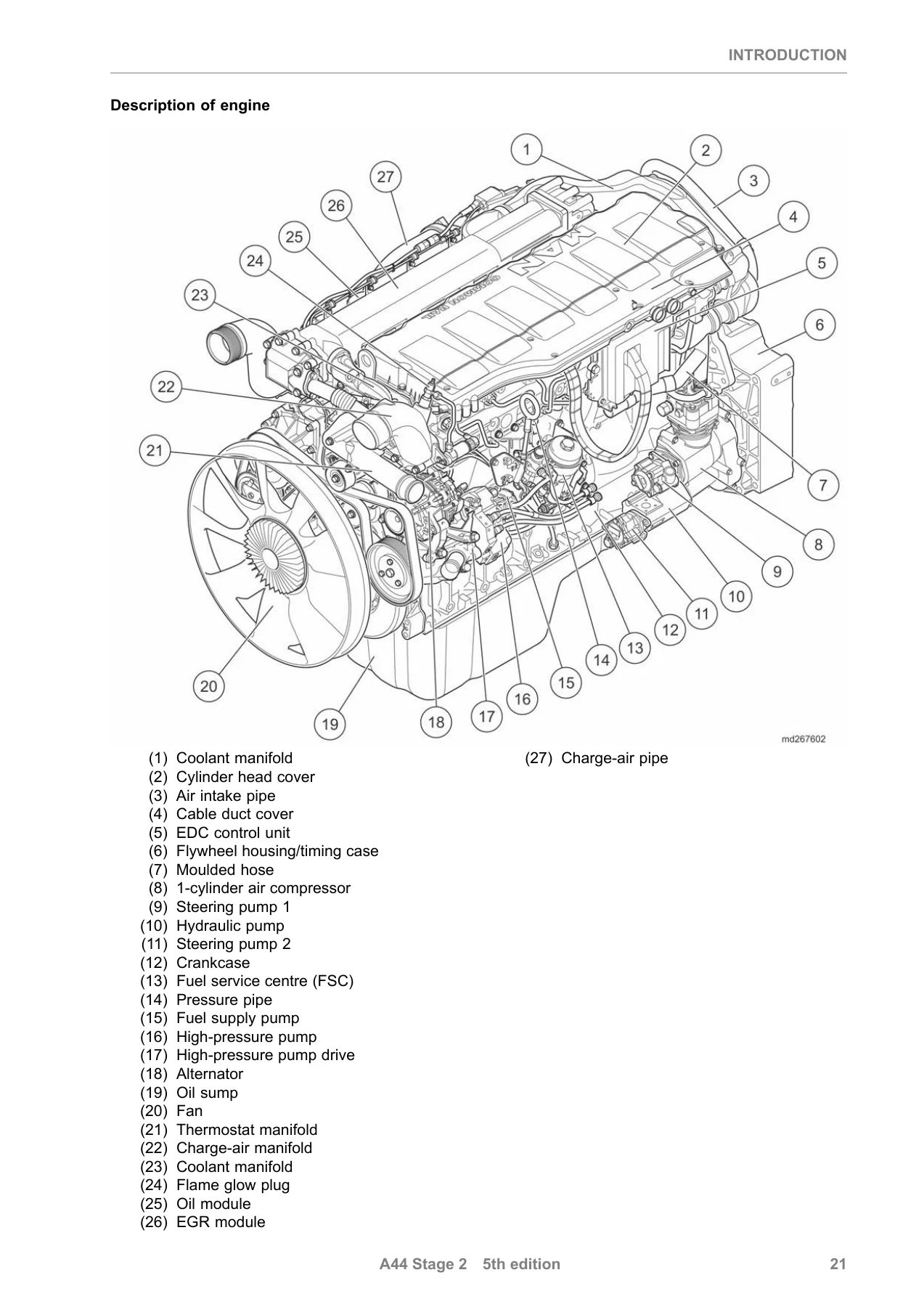
Covers safety instructions for working on the engine, including specific warnings for the Common Rail high-pressure system, battery and electrical work, welding, airbag systems and environmental protection. Also includes the model plate explanation, model designation breakdown, characteristic data tables for the D2676 LF01, LF05 and LF10, and a full description of the engine, crankcase, crankshaft, connecting rods, pistons, cylinder head, camshaft, lubrication, cooling, intake/exhaust, fuel system, high-pressure system, injectors, flame-start system and engine brake system.
Engine Electronics
Removing and installing the engine electronics for both the version without PriTarder and the version with PriTarder. Includes technical data for the oil pressure switch, charging pressure sensor, lambda probe, temperature sensor, speed sensor, crankshaft sensor, rail pressure sensor, proportional valve, FSC pressure sensor and exhaust gas back pressure sensor.
Cooling System
Removing and installing the fan, fan clutch and fan drive. Checking fan drive axial and radial play, fan shaft bearing internal diameter and fan shaft external diameter. Removing and installing the coolant manifold (with and without retarder), thermostats, thermostat housing, coolant pump, and distributor housing. Dismantling and assembling the coolant pump, including bearing, axial face seal, impeller and hub replacement. Removing and installing the coolant pre-heating.
Add-on Units
Removing and installing the steering pump and hydraulic pump in all configurations: one steering pump, two steering pumps, one steering pump with one hydraulic pump, one steering pump with two hydraulic pumps, and two steering pumps with one hydraulic pump. Removing and installing the 1-cylinder and 2-cylinder air compressors, including dismantling, assembling, checking PTO drive shaft axial play, and installing connectors and pressure relief valves. Removing and installing the starter motor, and the complete belt drive system including ribbed V-belt, guide rollers and tensioner.
Common-Rail-System
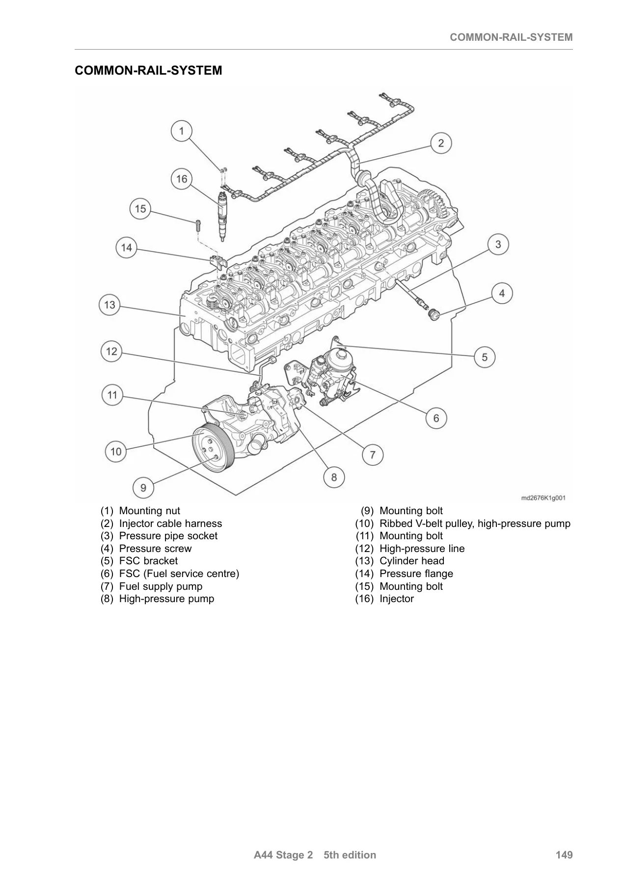
Protective sleeves for injectors and pressure pipe. Removing and installing injectors and pressure pipe, including extracting injectors, pressure pipe sockets, pressure screws and high-pressure lines. Detailed tightening sequences for injectors, pressure pipe and cylinder head cover. Removing and installing the high-pressure pump and high-pressure pump drive, including removing a seized pump, replacing the radial shaft seal, filling the pump with fuel and disassembling/assembling the pump and drive. Fuel filter system: protective sleeves, removing and installing the fuel service centre, dismantling and assembling the fuel service centre. Flame-start system: protective sleeves, removing and installing the flame-start system. EDC control unit: removing and installing.
Turbocharging
Removal and installation of the charge-air pipe and charge-air manifold. Removing and installing the turbo charger, including oil pressure line, oil return line, exhaust manifold attachment, and filling the turbo charger with oil before first start.
Intake/Exhaust System
Removing and installing the EGR module, including heat shields, connecting tube, air pipe, EGR adjusting cylinder, coupling pipes and oil rings. Dismantling and assembling the EGR module: check valves, intermediate flange, shut-off flap, and tightening sequences. Removing and installing the exhaust manifold, including heat shields, multi-piece rings and tightening sequences.
Cylinder Head
Removing and installing the rocker arm mechanism, checking rocker arm radial play, and dismantling/assembling the rocker arm mechanism. Removing and installing the cylinder head, including cylinder head bolt tightening sequence in five stages, cylinder liner protrusion check, and camshaft to TDC mark alignment. Checking and adjusting valve clearance for intake, exhaust and EVB. Removing and installing the valve-stem seals, including valve spring removal and installation.
Valve Control
Removing and fitting the camshaft and camshaft bearing, including checking camshaft axial and radial play, camshaft bearing shell spread, bearing shell inner diameter, camshaft bearing outside diameter and camshaft bearing depth. Checking the valve timing with valve lift measurement.
Timing Gears and Drive Wheels
Removing and installing the front drive wheels, including the high-pressure pump drive intermediate gear. Checking backlash, axial play, radial play, height and inside diameter of the intermediate gear and intermediate gear pin. Removing and installing the rear timing gears, including the large intermediate gear, small intermediate gear, air compressor intermediate gear, and rear crankshaft gear. Checking backlash, axial play and radial play for all intermediate gears.
Engine Lubrication
Removing and installing the oil module, including oil cooler, pressure relief valve, connecting manifold, oil separator and oil filter. Removing and installing the oil sump and oil intake pipe. Removing and installing the oil nozzles. Removing and installing the oil pump, including checking backlash, axial play and radial play of the ring gear, checking oil pump pinion and shaft dimensions, and replacing the bearing bush.
Crankshaft Seals
Removing and installing the front crankshaft seal, including determining the repair level and pressing in the seal at the correct depth. Removing and installing the rear crankshaft seal.
Crank Drive
Removing and installing the vibration damper for versions without and with PriTarder. Removing and installing the flywheel for the manually operated gearbox, including starter ring gear replacement, flywheel wear check and flywheel axial run-out check. Removing and installing the flywheel for the automatic gearbox. Removing and installing the piston and connecting rod, including piston ring checks, connecting rod bearing checks and piston protrusion measurement. Removing and installing the crankshaft, including checking axial and radial play, crankshaft bearing journal dimensions, and crankshaft bearing shell spread.
Engine Housing
Removing and installing the flywheel housing/timing case for variants with and without cable-controlled gearshift. Removing and installing the cover. Removing and installing the cylinder liners, including checking cylinder liner protrusion, seat depth and O-ring replacement.
PTO (Power Take-offs)
Removing and installing the PTO for offset gearbox, output flange, hydraulic pump attachment, 4-hole flange and 2-hole flange variants. Dismantling and assembling the PTO for the offset gearbox variant, including drive shaft, output shaft, bearings, grooved nut and mounting flanges.
Engine Brake System
Removing and installing the PriTarder, including draining coolant, removing coupling pipes, pressure sensor, screw connectors and axial face seal. Removing and installing the engine brake, including proportional valve, solenoid valve, adjusting cylinder, exhaust pipe and pressure sensor. Setting the adjusting cylinder pre-load.
Technical Data
A complete reference section listing all torque values, clearances, wear limits, adjustment values and dimensional specifications for the D2676 engine, organised by chapter and component.
Why This Manual Matters
The MAN D2676 is a high-pressure Common Rail engine. The fuel system alone operates at pressures of 1800 bar and above. The injectors, high-pressure pump and pressure pipe are precision components that demand absolute cleanliness and exact torque sequences. Get a pressure pipe socket torque wrong and you risk a fuel leak at 1800 bar. Skip a cylinder head bolt stage and you compromise the head gasket. Use the wrong valve clearance and you burn a valve. This manual removes the guesswork.
It is not a generic engine guide. Every procedure, every torque figure and every wear limit in this document is specific to the D2676 LF01, D2676 LF05 and D2676 LF10 engines. The manual covers the full engine mechanically and electronically, from removing a fan clutch to extracting a seized high-pressure pump, from checking piston protrusion to programming the EDC control unit. If you maintain, repair or overhaul these engines, this is the reference you keep on the workshop laptop or print out for the bay.
What You Can Do With This Manual
With this repair manual you can confidently:
- Remove, test and refit injectors, pressure pipe sockets and high-pressure lines with the correct torque and tightening sequences
- Remove and install the high-pressure pump, including the special procedure for a seized pump
- Set valve clearance for intake, exhaust and EVB on all six cylinders
- Remove and install the cylinder head, follow the five-stage bolt tightening sequence and check cylinder liner protrusion
- Check and adjust camshaft axial and radial play, and verify valve timing
- Remove and install the crankshaft, measure bearing clearances and select the correct bearing shells
- Remove and install pistons and connecting rods, check piston ring gaps and piston protrusion
- Diagnose and repair the EGR module, turbo charger, charge-air system and exhaust manifold
- Service the cooling system, oil module, oil pump and fuel service centre
- Remove and install the PriTarder and conventional engine brake system
- Look up every torque value, clearance and wear limit in the technical data chapter
Whether you are a workshop technician, a fleet maintenance manager or an owner-operator who does their own repairs, this manual gives you the information to do the job correctly the first time. It is the same level of documentation used in professional MAN service environments.
IMAGES PREVIEW
Instant PDF Delivery – No Shipping, No Waiting
This MAN D2676 repair manual is delivered as an instant PDF download immediately after payment. There is no physical book to ship, no waiting for delivery and no customs delays. You can download it once and keep it on your computer, laptop, tablet or smartphone. Print individual pages or entire chapters for use in the workshop. The PDF works on any device with a PDF reader, so you can access the information wherever you are working. Search, zoom and navigate the document with the tools already built into your PDF software.
Stop relying on guesswork or incomplete forum posts. Get the complete 5th edition MAN D2676 LF01, LF05, LF10 Common Rail repair manual and have the correct procedures and specifications at your fingertips.
Reviews
There are no reviews yet.