
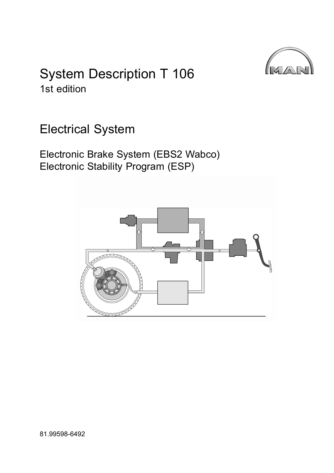
MAN EBS2 Wabco ESP Electronic Brake System System Description T106 – TGL TGM Lion’s Star Coach Regio Bus PDF
Original price was: $47.95.$29.95Current price is: $29.95.
MAN System Description T 106 covering EBS2 Wabco Electronic Brake System and Electronic Stability Program (ESP) across TGL, TGM, Lion’s Star, Lion’s Coach and Lion’s Regio models. 182-page English PDF with full component, functional and diagnostic detail.
Description
MAN EBS2 Wabco ESP – System Description T 106
This is the complete MAN System Description T 106, first edition, published by MAN Nutzfahrzeuge Aktiengesellschaft under document number 81.99598-6492. It is the technical reference for the EBS2 Wabco Electronic Brake System and the integrated Electronic Stability Program (ESP) fitted to TGL, TGM trucks and MAN buses and coaches. The manual covers system architecture, electro-pneumatic control, pneumatic redundancy, component design, functional behaviour and the full SPN diagnostic error list used by MAN-cats II.
File Details
- Manual type: System Description
- Brand / publisher: MAN Nutzfahrzeuge Aktiengesellschaft
- Document number: 81.99598-6492
- Edition: T 106, 1st edition
- Copy deadline: 11.2005
- Language: English
- Pages: 182
- Format: PDF
- Systems covered: EBS2 Wabco, ESP, ABS, ASR, EPB, BMM
- Applicable vehicles: TGL, TGM, Lion’s Star, Lion’s Coach, Lion’s Regio, plus additional MAN bus and coach chassis
Chapters Covered
- Introduction (safety instructions, model overview, wiring diagram notes)
- Device Description
- Functional Description
- Component Description
- Diagnosis
- Function Diagrams and Wiring Diagrams
Introduction and Wiring Diagram Notes
The opening section lays out the safety instructions that apply when working on the brake system, the electrical system and polyamide tubing, along with a full overview of models covered by T 106. It also explains the wiring diagram layout used throughout the manual: component designations, installation positions, plug connections, cable designations, line interrupts and current path numbering. This is what lets you read the function diagrams quickly during fault-finding.
Device Description – EBS and ESP System Architecture
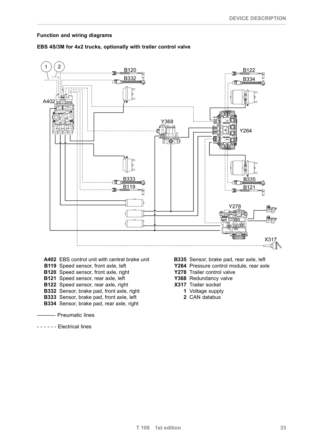
The device description introduces the full EBS sub-function set: EPB (Electro-Pneumatic Brake), ABS, ASR, BMM (Brake Management) and ESP. It explains the purely pneumatic dual circuit with its overlaid electro-pneumatic single circuit, and the automatic switch to pneumatic redundancy if the electrical side fails. Three hardware variants are described in detail: 4S/3M (4 speed sensors, 3 pressure modulators), 4S/4M (4 speed sensors, 4 pressure modulators) and 6S/6M (6 speed sensors, 6 pressure modulators). The voltage supply concept, pressure selection logic, ESP vehicle model adaptation and the interfaces to other vehicle systems (Powertrain CAN, Trailer CAN, Brake CAN, Sensor CAN) are all laid out here.
Functional Description – How the Systems Operate
This is where the manual gets into the day-to-day behaviour of the brake system. It covers the electronic brake pressure control chain from the central brake unit to the pressure control modules and trailer control valve; the pneumatic redundancy paths at the front axle, rear axle and trailer pilot control; brake force distribution; deceleration control; auxiliary brake integration and limiting; brake wear harmonisation; tractor/trailer compatibility control; trend detection; Brake Assist; drag torque control; speed sensing and calibration; and the frequent-stop brake. The ABS, ASR and ESP functions are each described in their own right, including brake intervention and engine intervention logic for ESP, the Roll Stability Program (RSP) stages, and the limits of the ESP function.
Component Description – Central Brake Unit, Modulators, Sensors and Valves
Each major EBS/ESP component gets its own design and installation-position write-up with photos. Coverage includes the central brake unit with EBS control unit (G7.350 / G7.351 / A402), the two-channel pressure control module for the rear axle (G67.351 / G67.353 / Y264), the redundancy valve (G15.350 / Y368), the front-axle ABS pressure control valves (G67.202 / Y125, Y126), the trailer control module (G17.350 / Y278), inductive speed sensors (B119, B120, B121, B122, B223, B224), brake pad wear sensors (B332-B335, B388, B389), the steering angle sensor (B475), and the combined rotational speed and lateral acceleration sensor (B476). Connector pin assignments, pneumatic schematics and the measuring principles behind the ESP sensors are included.
Diagnosis – SPN Error Codes and MAN-cats II Procedure
The diagnosis chapter is the practical heart of the manual for anyone troubleshooting an EBS/ESP fault. It explains how error states are transferred over the CAN databus and shown on the instrumentation via the central warning light (H111), check lamp H108, directional stability check lamp H415 and the pad wear indicator. The full SPN list and error code descriptions run through the manual – each entry gives the SPN, FMI, error indication, effect of error, cause of error and the remedy. Control unit pin assignments, the X200 diagnosis socket installation positions for TGL/TGM (old and new versions), and the adapter cable for MAN-cats II are all documented. There are also malfunction indicator priorities and the structure of error text messages on both Baseline and Highline instrumentation.
Function Diagrams – Wiring, Pneumatic and Redundancy Schematics
The function diagrams at the back of the manual give full schematic coverage for the different vehicle installations. Separate diagrams are provided for TGL 10-12.xxx with and without trailer, TGL 7/8.xxx with and without trailer, TGM 18.xxx with and without trailer, plus diagrams for specific platform codes (4S/4M for R12/P23/R02/R07/P21/A51/R33 and 6S/6M for R13/P24/R03/R08/P22). Additional diagrams cover the EBS 4S/3M/4M layout with ESP, the front-axle EBS pressure control valves, the EBS redundancy valve, the EBS trailer control module, the ASR slip threshold button, the ASR check lamp, the EBS/ABS trailer socket, and the 6×2 TEPS and 4×2 TEPS chassis variants.
What This Manual Lets You Do
With this MAN EBS2 Wabco ESP System Description in hand, a technician can diagnose the full electro-pneumatic brake system with confidence. You get the complete SPN error list with FMI codes and the MAN-cats II gateway procedure, so you know exactly where to look when the central warning light comes on. You get the component-level detail needed to test and replace the central brake unit, pressure control module, redundancy valve, trailer control module, speed sensors, wear sensors, steering angle sensor and rotational speed sensor. You get the pneumatic redundancy paths laid out so you can follow what happens to the brake system when the electrical side drops out. And you get the wiring diagrams for multiple TGL, TGM, Lion’s Star, Lion’s Coach, Lion’s Regio and TRENDLINER installations, so you are not guessing which connector goes where.
Having the correct procedures and the exact technical values for a system this integrated matters. EBS and ESP sit on the same CAN databus as the engine management, transmission control and vehicle management computer, so a wrong reading or an incorrect replacement can cascade into drivability and safety errors. This manual tells you what to check, in what order, and why.
IMAGES PREVIEW
Delivery is instant. This 182-page PDF downloads immediately after payment, with no shipping and no waiting. Read it on any device – laptop, tablet or phone – and print the pages you need for the workshop floor. Keep the full manual at hand and you have the complete MAN EBS2 Wabco ESP reference whenever a truck, bus or coach comes in.
Reviews
There are no reviews yet.