
MAN EDC7 Common Rail Injection System T18 – Electrical System Service Manual 6th Edition PDF
Original price was: $67.95.$44.95Current price is: $44.95.
Complete MAN EDC7 common-rail system description and electrical service manual (T 18, 6th edition, doc 81.99298-6842). Covers EDC7 C3, C32 control units, CP3.4 / CP9V4 high-pressure pumps, injectors, rail, sensors, actuators, diagnosis, SPN fault lists, hydraulic test step lists and full wiring diagram overviews for D08 through D28 and D2840/D2868 V-engines.
Description
MAN EDC7 Common Rail Injection System T18 – Electrical System Service Manual (6th Edition)
This is the complete MAN EDC7 Common Rail Injection System system description and electrical service manual, published as document 81.99298-6842 and issued as the 6th edition T 18. It is the technical reference MAN Nutzfahrzeuge AG produced for its own workshops and service partners, and it walks through the entire EDC7 common-rail architecture – from the control unit pin assignments and the CP3.4 / CP9V4 high-pressure pumps, through the MProp metering unit, rail, pressure-limiting valve and injectors, all the way to the diagnosis sockets, SPN fault list, hydraulic test step lists and the wiring diagram overviews. Whether you are chasing an SPN 3775 rail pressure fault, pinning out an EDC7 C32 engine connector, or setting up an EGR controller, the procedure and the values are in here.
File Details
- Manual type: System Description / Electrical Service Manual
- Brand: MAN Nutzfahrzeuge AG
- Document number: 81.99298-6842
- Manual designation: T 18 (System Description, Electrical System, Common-Rail Injection System EDC7)
- Edition: 6th edition
- Publication / copy deadline: 07.2010
- Language: English
- File format: PDF
- Page count: Approximately 398 pages
- Covered engine families: D08, D20, D26, D28, D0834, D0836, D2066, D2840, D2842, D2848, D2868, D2876
- Covered control units: EDC7 C3 (A435), EDC7 C32 (A435, A570), Master/Slave configurations
Chapters Covered
- Safety Instructions and Introduction
- System Description – Structure and Operation of the Common-Rail System
- Functional Description – Control Unit EDC7 (A435, A570)
- High-Pressure Pump (CP3.3, CP3.4, CP3.4+, CP3.4H+, CP9V4)
- Metering Unit (MProp, Proportional Valve for Fuel)
- High-Pressure Accumulator (Rail), Pressure-Limiting Valve, Rail-Pressure Sensor
- Injectors (Y341 – Y350)
- Crankshaft / Camshaft Speed Sensors and all other system sensors
- AdBlue, NOx, Oxygen, Exhaust Gas and Charge-Pressure Sensors
- Turbocharger Pulse Valve, EGR Controller, E-EGR, Compressed Air Shut-Off Valve
- Component Description / Installation Positions
- Diagnosis – K-Line Structure, Diagnosis Sockets, SPN List EDC7, Test Step Lists, Hydraulic Test Step List, Troubleshooting with MAN-cats
- Wiring Diagrams – Overviews for EDC7 C32 Euro 4/5, C3 Euro 3, Master/Slave and DCU15
Control Unit EDC7 and Functional Description
The manual opens the functional section with the EDC7 control unit itself – its three connectors (engine A, vehicle B, injector C) and the full pin-by-pin assignment tables for the EDC7 C32 Euro 4/5, EDC7 C32 Master / Slave Euro 5 V8, EDC7 C3 Euro 3 and EDC7 C3 Master / Slave V10 configurations. Every pin row lists the line number, wire colour where applicable, and the function the pin performs (supply, ground, actuator output, sensor signal, CAN line and so on). This is the reference you need when a fault points you at a specific connector, and it also documents how the two control units in a Master / Slave V-engine split the cylinders between them.
High-Pressure Pump and Fuel Metering
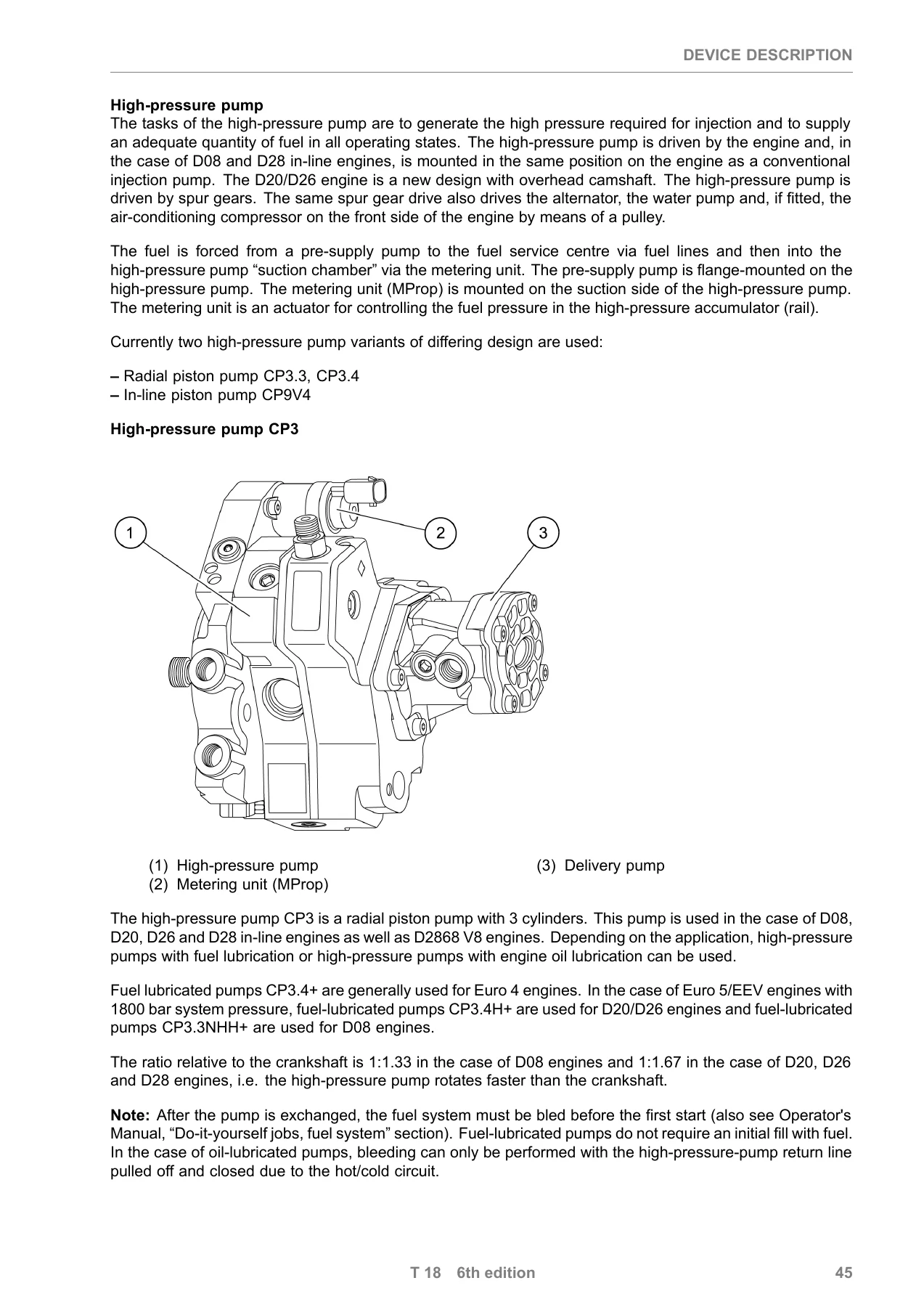
Both high-pressure pump families are covered in detail: the radial-piston CP3.3 / CP3.4 / CP3.4+ and the in-line CP9V4 for the large V-engines. Drive ratios to the crankshaft, the difference between fuel-lubricated and oil-lubricated variants, and the metering unit (MProp) that controls rail pressure on the suction side of the pump are all explained, together with the PWM duty-cycle logic (0% = open / maximum delivery, 100% = closed / zero delivery). The metering unit pin assignment, its position on the CP3.4 and CP9V4 housings, and the matching instructions for replacement units are included.
Rail, Pressure-Limiting Valve and Injectors
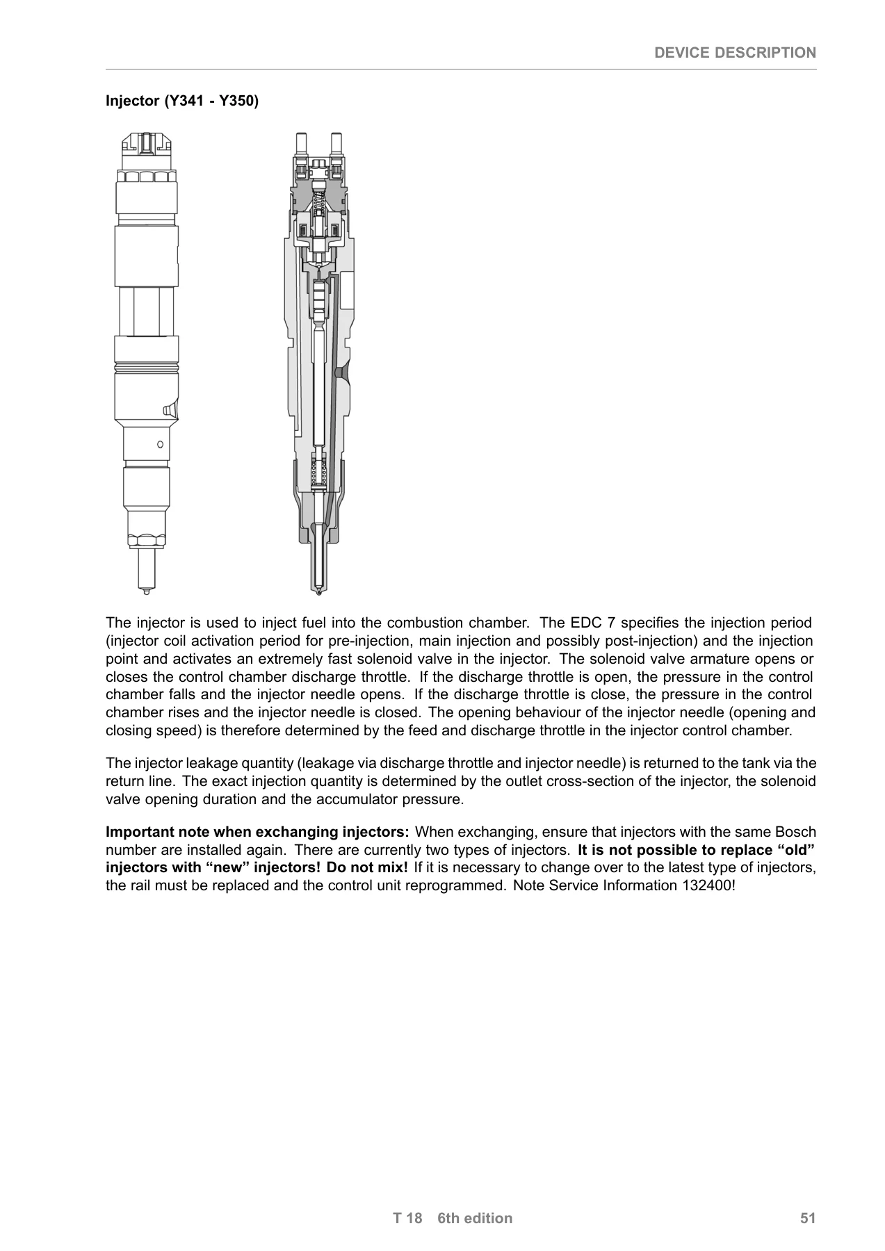
The high-pressure accumulator, the pressure-limiting valve and the rail-pressure sensor are treated together, including the sensor curve that maps rail pressure in bar to output voltage. The pressure-limiting valve’s two-stage behaviour, its forced-opening strategy and the way it protects the system are all described. Injector operation is covered from the solenoid valve and control chamber through to the needle opening characteristics, along with the warnings about not mixing old and new injector types and the need to reprogram the control unit if a change-over is required.
Sensors and Actuators
Every sensor on the EDC7 common-rail engine is documented – crankshaft speed (increment) sensor, camshaft speed (segment) sensor, oil pressure, fuel pressure, Kavlico and Bosch LDF 6 / LDF 6T charge-pressure sensors, charge air temperature, coolant temperature (including the LT-cooler sensor), exhaust gas temperature sensors (B561 / B633 / B634), AdBlue fill level / temperature sensor, NOx sensor, oxygen sensor, exhaust gas differential and relative pressure sensors, turbocharger pulse valves, the EGR controller and the position-controlled E-EGR with travel sensor, the compressed air shut-off valve and the LT-cooler shut-off / pressure-reducing valve. Sensor curves, resistance tables and pin assignments are given for each.
Diagnosis, SPN List and Test Step Lists
The diagnosis chapter starts with the K-line structure and both the 12-pin MAN diagnosis socket and the 16-pin HD-OBD socket to ISO 15031-3, including the adapter cable part number. The full SPN list then documents every fault the EDC7 can store – what the control unit is monitoring, the FMI states, the system response and any remarks. This is followed by the test step lists for EDC7 C32 Euro 4, C32 Euro 5 with in-engine EGR, C32 Euro 5 with MAN AdBlue, C32 Master / Slave Euro 5 V8, C3 Euro 3 and C3 Master / Slave Euro 3, with the resistance and voltage values you should measure at each pin pair.
Troubleshooting and Hydraulic Test Procedures
Practical fault-finding is covered by the troubleshooting chart, the troubleshooting program, and the MAN-cats routines – compression test, high-pressure test, DLS coil tester, PLV Open Test, rev-up test, cylinder shut-off test and smooth-running control. The hydraulic test step list explains how to measure total leakage volume, individual injector leakage, pressure-limiting valve leakage and high-pressure pump delivery rate, with the correct return volumes for each engine family and the exact connection points on the D2876 pressure measuring lines.
Wiring Diagrams
The manual ends with the wiring diagram overviews – EDC7 C32 Euro 5 OBD 1 with NOx monitoring, EDC7 C32 Euro 5 Master / Slave, EDC7 C32 Euro 5 EGR OBD 2, EDC7 C32 Euro 4 OBD 1 with and without NOx monitoring, EDC7 C3 Euro 3, EDC7 C3 Euro 3 Master / Slave, and the AdBlue DCU15 overviews in single and Master / Slave form. Each legend lists the components, fuses, plug connections and injector designations used in the diagram.
What This MAN EDC7 T18 Manual Lets You Do
With this document on your workshop PC or tablet you can pin out the EDC7 control unit without guessing which pin carries the sensor supply and which is the signal ground, follow the fault memory SPN entries from symptom to component, measure the exact resistance and voltage a circuit should show at a given pin pair, diagnose low-pressure and high-pressure fuel faults using the leakage and delivery volume figures, run the MAN-cats routines the correct way, and cross-check every sensor against the curve the control unit expects to see. The wiring diagram overviews let you trace a CAN line, an injector bank or an AdBlue signal through the whole vehicle rather than working from memory.
Doing this work without the manual means guessing pin numbers, guessing torque-free electrical values and risking misdiagnosis – especially on the common-rail high-pressure side where a wrong part or a wrong procedure can destroy an injector or a pump. Having the 6th edition T 18 document open in front of you is what separates a correct repair from a repeat comeback.
IMAGES PREVIEW
Instant PDF delivery. As soon as your order is confirmed the file is available for download – no shipping, no waiting, and no postage cost. Read it on a laptop, tablet or phone, print the pages you need for the workshop, and keep the rest on file. The MAN EDC7 Common Rail Injection System service manual is a working document, and this is the full T 18 6th edition version of it.
Reviews
There are no reviews yet.