
MAN TGS TGX Electrical Components Removal and Installation Repair Manual N02 – PDF Download
Original price was: $54.95.$34.95Current price is: $34.95.
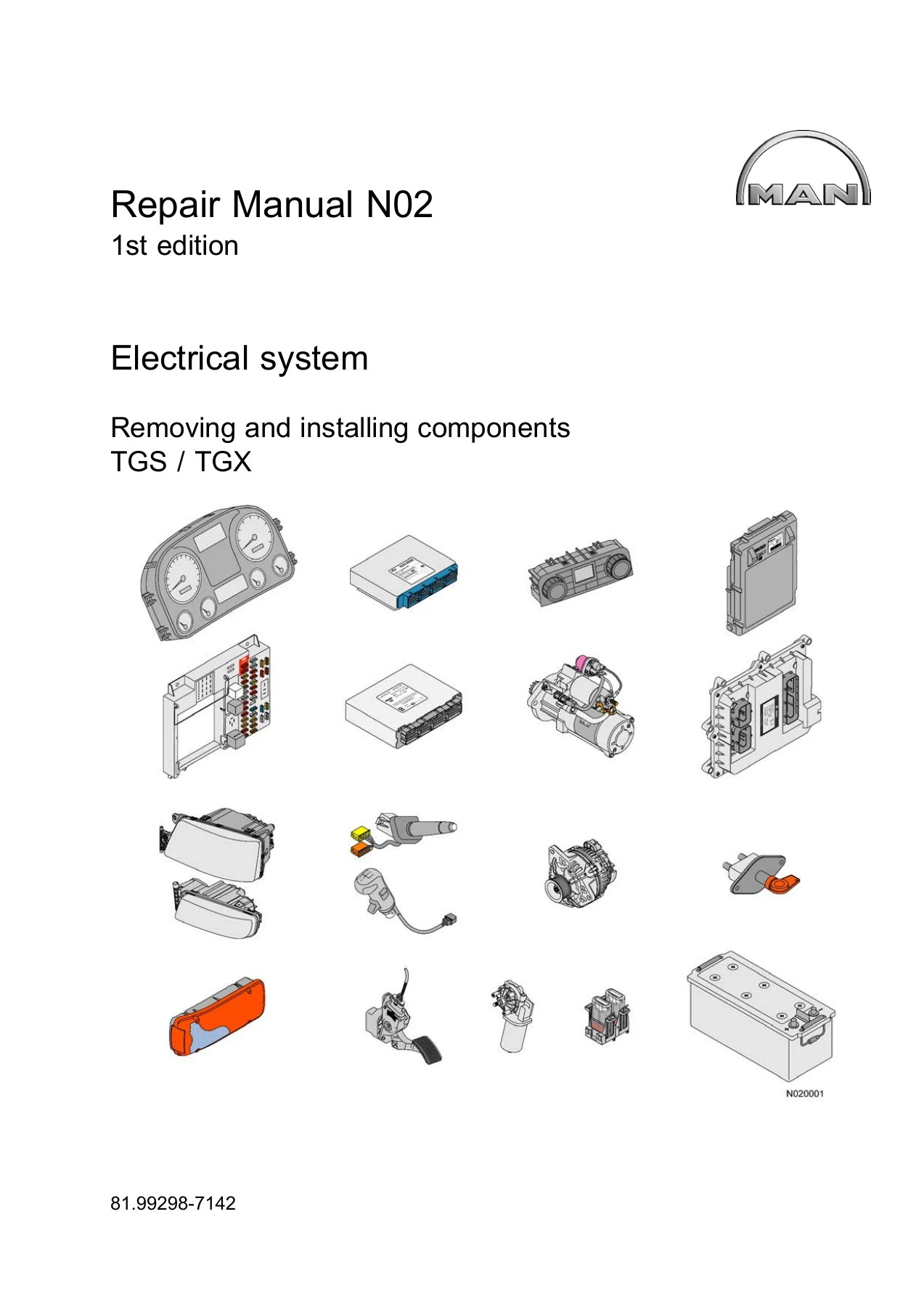
MAN TGS / TGX Electrical Components Removal and Installation Repair Manual N02 (81.99298-7142). Covers control units, sensors, lighting, fuses, batteries, alternator, starter and switches for MAN TGS and TGX trucks. 168-page English PDF, 1st edition.
Description
MAN TGS / TGX Electrical Components Repair Manual N02 — Removal and Installation Guide
The MAN TGS / TGX Electrical Components Removal and Installation Repair Manual N02 is the workshop document covering the electrical system of MAN TGS and TGX trucks. Published under document number 81.99298-7142 as a first edition, this manual provides the removal and installation procedures for electrical components across the vehicle — from control units and sensors to lighting, fuses, batteries, alternator, starter, and switches. Every procedure is supported by the tightening torques and technical data required to complete the work correctly and safely.
File Details
- Manual type: Repair Manual — Electrical Components Removal and Installation
- Brand: MAN
- Models covered: TGS, TGX
- Document number: 81.99298-7142
- Edition: 1st edition (1. Ausgabe)
- Language: English
- Page count: 168
- File format: PDF
Chapters Covered
- A — Control units, switch units, subassemblies
- B — Sensors, probes, transmitters
- E — Lighting, bulbs
- F — Fuses, current limiters
- G — Batteries, alternator
- M — Electric drives
- Q — Power relay, battery master switch, EMERGENCY OFF switch
- S — Switches
Control Units, Switch Units and Subassemblies (A)
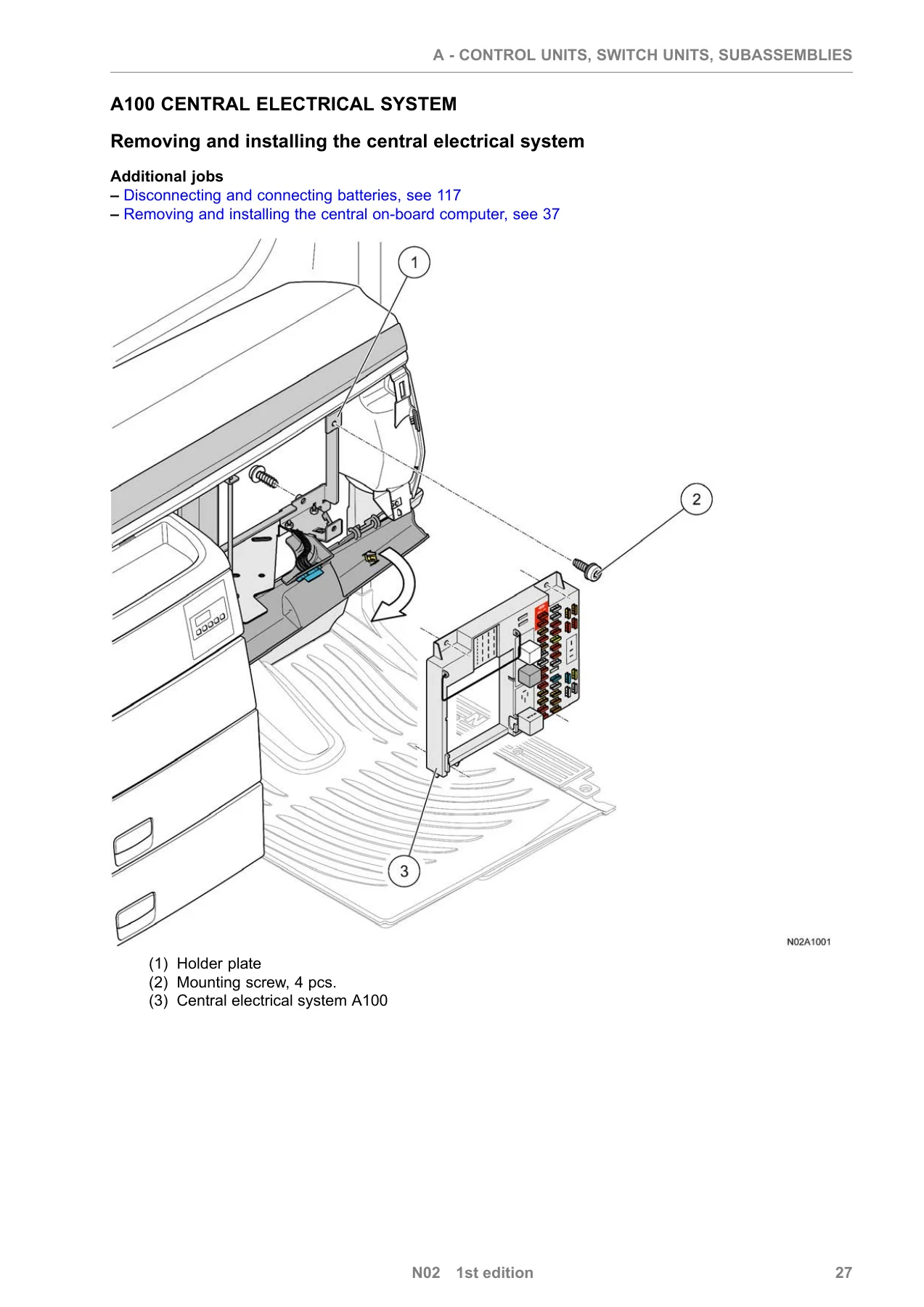
This chapter covers the central electrical system, the radio/cassette player and aerial, the central on-board computer (ZBR), the electronic brake system (EBS) control unit, the vehicle management computer (FFR), instrumentation, the tachograph, the accelerator pedal unit, the cruise control/retarder steering column switch, the engine control unit EDC7 (D26), the door module, the heating control element, the immobiliser, and the multifunctional steering wheel contact carrier. Procedures include component removal, disconnection of electrical plug connections, installation, and tightening specifications. Wiring harness routing and cable tie placement are noted where relevant. The central electrical system section details the folding holder plate, marking of plug connections before disconnection, removal of cables with screw connections, and the tightening of hexagon lock nuts with the specified torque screwdriver and holding device.
Sensors, Probes and Transmitters (B)
The tank transmitter and pulse generator (KITAS) are covered in this section. The manual details fuel line removal using the specified release tools, the importance of sealing fuel lines and connections immediately, and the renewal of O-rings and sealing rings. The pulse generator procedure includes seal fitting and parameter setting requirements after renewal.
Lighting and Bulbs (E)
Low and high-beam headlights, front outline lights, additional high beam headlights, side turn indicators (H124/H125), and rear lights (A189/A190) are covered with their respective removal and mounting instructions. Mounting screw torque values are given for headlights, holders, indicator glass, rear light sleeve nuts, and lens screws. The manual notes specific procedures such as the bulb extension removal for rear light access and the mounting screw that remains in the bumper during headlight removal.
Fuses and Current Limiters (F)
This chapter addresses fuse carriers, fuses of the central electrical system and relay holders, fuses distributed in the battery box, the F229 fuse for trailer charging, and the F522/F523 fuses for continuously operating consumers. The component mounting diagram on the rear of the co-driver’s side instrument panel is referenced for fuse installation location and rating. The distributor box and automatic circuit breaker procedures include tightening torques for mounting screws, cover screws, and clamping screws.
Batteries and Alternator (G)
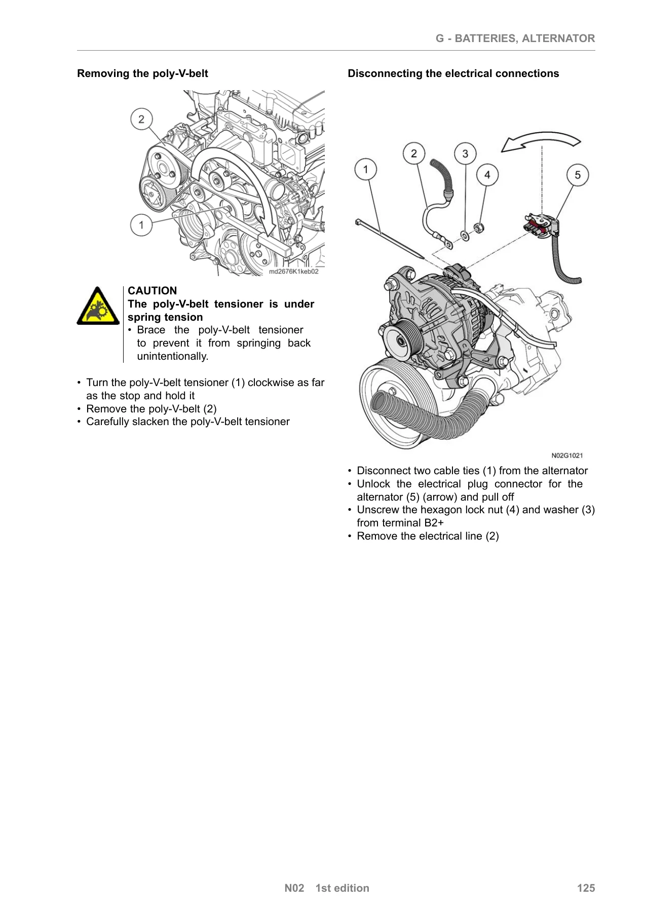
Battery disconnection and connection procedures emphasise terminal order — negative first when disconnecting, positive first when connecting — along with the required terminal grease and mounting nut torque of 6 Nm. Battery removal and installation covers holding clips, series links, terminal covers, and the 175 Ah battery capacity with a weight of 39 kg. The alternator section covers the NBC1 and LEB10 alternators, poly-V-belt removal and installation, electrical connections at terminal B2+, mounting screw torques, and the engine/alternator speed ratio of 1:4. The poly-V-belt tensioner caution is highlighted, and the procedure for mounting the alternator holder and connecting electrical cables is described in detail.
Electric Drives (M)
The starter and windscreen wiper motor are covered. Starter procedures include right noise shield removal, intake pipe removal, induction port removal, electrical disconnection at terminal 30, and mounting screw tightening to 70 Nm. The flywheel ring gear can be inspected through the starter assembly opening using the engine barring gear and gear ratchet. Windscreen wiper motor procedures include the parked-position requirement and electrical plug connection before mounting, with mounting nut torque of 25 Nm and mounting screw torque of 12 Nm.
Power Relay, Battery Master Switch and Emergency Off Switch (Q)
The starter switch (Q101) removal and installation is covered, with steering column jacket removal steps and the 3.5 Nm mounting screw torque for the starter switch. The ignition key must be set to position “0” in the ignition lock before removal.
Switches (S)
Battery master switch (S100), steering column switch for turn indicators, wipers and headlights (S108), and gear selector lever switch (S477) are covered. Procedures include steering column jacket removal and installation, electrical plug connection handling, and tightening torques for steering column switch mounting screws (8 Nm) and selector grip (30 Nm). The battery master switch section covers terminal lug mounting nut torque of 20 Nm and mounting screw torque of 10 Nm.
Safety Instructions
The manual opens with detailed safety instructions covering accident prevention, work on brake systems, compressed natural gas (CNG) systems, high-pressure lines, injector nozzles, vehicle electrical systems, battery handling, electric welding, painting, cab tilting, air-conditioning systems, airbag and belt tensioner units, independent heaters, and common-rail systems. Battery acid warnings, AdBlue handling precautions, and environmental protection measures are also addressed. These instructions are essential reading before any work begins on the vehicle’s electrical system.
Technical Data
A technical data section consolidates tightening torques and specifications for the components covered, including the central electrical system mounting screws (7 Nm), battery cable terminals (6 Nm), alternator mounting screws (65–80 Nm), starter mounting screws (70 Nm), and numerous other values. The manual also includes model plate explanations for the central on-board computer (ZBR 2), the vehicle management computer (FFR), the EBS control unit, the engine control unit, the starter, and the alternator, aiding in component identification.
Put This MAN TGS / TGX Electrical Repair Manual to Work
Whether you are replacing a failed control unit, tracing an electrical fault, removing a starter, or renewing a battery, the MAN TGS / TGX Electrical Components Removal and Installation Repair Manual N02 gives you the procedures and specifications to do the job properly. It is the document technicians reach for when they need to know the correct sequence for disconnecting electrical plug connections, the tightening torque for a battery terminal, or the safety precautions for working on the common-rail system.
IMAGES PREVIEW
This MAN TGS / TGX electrical repair manual is delivered as an instant PDF download. There is no shipping, no waiting, and no physical book to lose. The file works on any device — laptop, tablet, or smartphone — and pages can be printed for use in the workshop. After payment, the download link is available immediately so you can get straight to work on your MAN TGS or TGX truck.
Reviews
There are no reviews yet.