
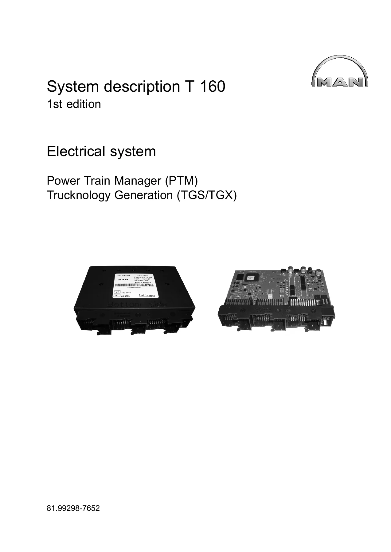
MAN TGS TGX Power Train Manager PTM System Description T160 – Electrical System Repair Manual PDF 81.99298-7652
Original price was: $52.95.$34.95Current price is: $34.95.
MAN Truck & Bus AG Power Train Manager (PTM) System Description T160 – 1st edition, 2012, part number 81.99298-7652. 150-page electrical system manual for TGS/TGX trucks: PTM (A1124), CAN and LIN buses, pedal unit, fan clutch, multi-function steering wheel, full SPN/FMI diagnostics, break-box test step list and circuit diagrams. Instant PDF download.
Description
This is the complete MAN Truck & Bus AG Power Train Manager (PTM) System Description T160 — the electrical-system service manual for TGS and TGX trucks built on the Trucknology Generation S and Trucknology Generation X platforms. Published as part number 81.99298-7652 under the 1st edition (2012), it is the reference MAN technicians use to understand, diagnose and repair the Power Train Manager (A1124) and every networked system it controls across the driveline.
File Details
- Manual type: Electrical system / System description (repair manual)
- Brand: MAN Truck & Bus AG
- Model: TGS / TGX — Trucknology Generation S and X
- Document number: T160
- Part number: 81.99298-7652
- Edition: 1st edition, 2012
- Language: English
- Page count: 150 pages
- File format: PDF
Chapters Covered
- Abbreviations
- Introduction and Safety Instructions
- Type Overview
- Operating Instructions for Circuit Diagrams
- Device Description — System Description
- Functional Description
- Description of Components
- Diagnostics
- SPN Diagnostic Code Description
- Test Step List
- Additional Circuit Diagrams
Safety Instructions
Regulations for preventing accidents leading to injury to personnel, guidelines for preventing damage and premature wear on units, limited liability for spare parts and accessories, and environmental contamination precautions. Includes specific guidance for working on the brake system, high-pressure lines, vehicle electrical systems, CNG vehicles, airbags and belt pretensioners, air-conditioning, independent heaters, and the MAN Common Rail system — including the heart-pacemaker warnings and fuel-jet hazard statements that any technician working on these trucks must read before touching the rail.
Type Overview
Full model listings for Trucknology Generation S (01S – 99S, 01M – 99M, 01W – 99W) and Trucknology Generation X (01X – 99X) — covering the TGS 18.D20/D26 4X2 BB through the TGS 35/41.D20/D26 8X8 BB, the MIL variants, the WW (military/export) variants, and the TGX series from 18.D20/D26 4X2 BLS up to the 41.V8 8X4/4 BLS. Every model designation is reproduced exactly as MAN prints it, so you can confirm at a glance whether your truck’s chassis code is covered.
Operating Instructions for Circuit Diagrams
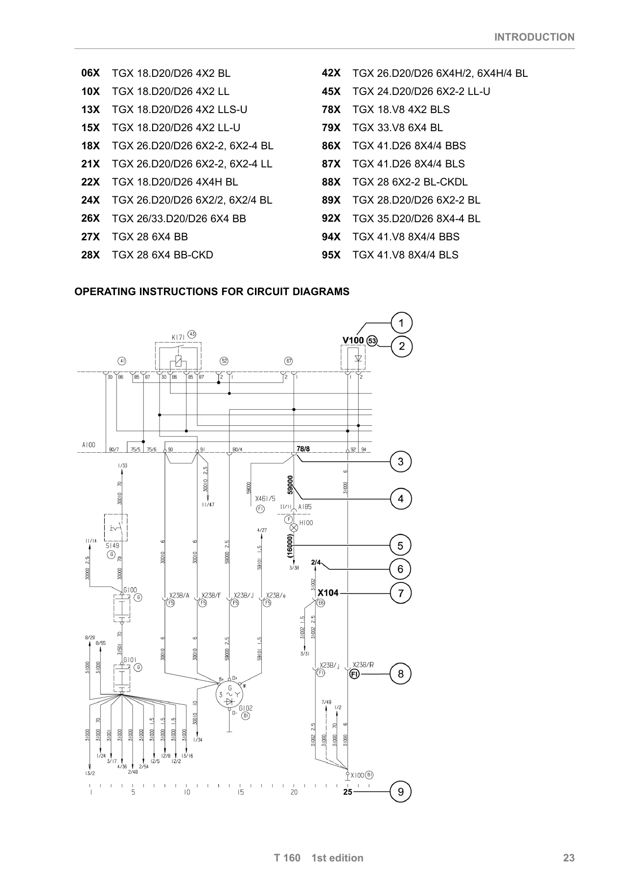
How to read MAN’s circuit-diagram notation — component designations, installation locations on the front of the central electrical system, plug connectors on the back of the central electrical system, cable numbers with colour abbreviations and cross-sections, crimp connectors, line disconnections with sheet and path numbers, and current-path numbering. Installation location diagrams for both left-hand-drive and right-hand-drive TG vehicles are included with A-pillar, B-pillar, instrument panel, steering column, pedals, front wall, gearshift console, battery box and frame references.
System Description and CAN Data Bus Structure
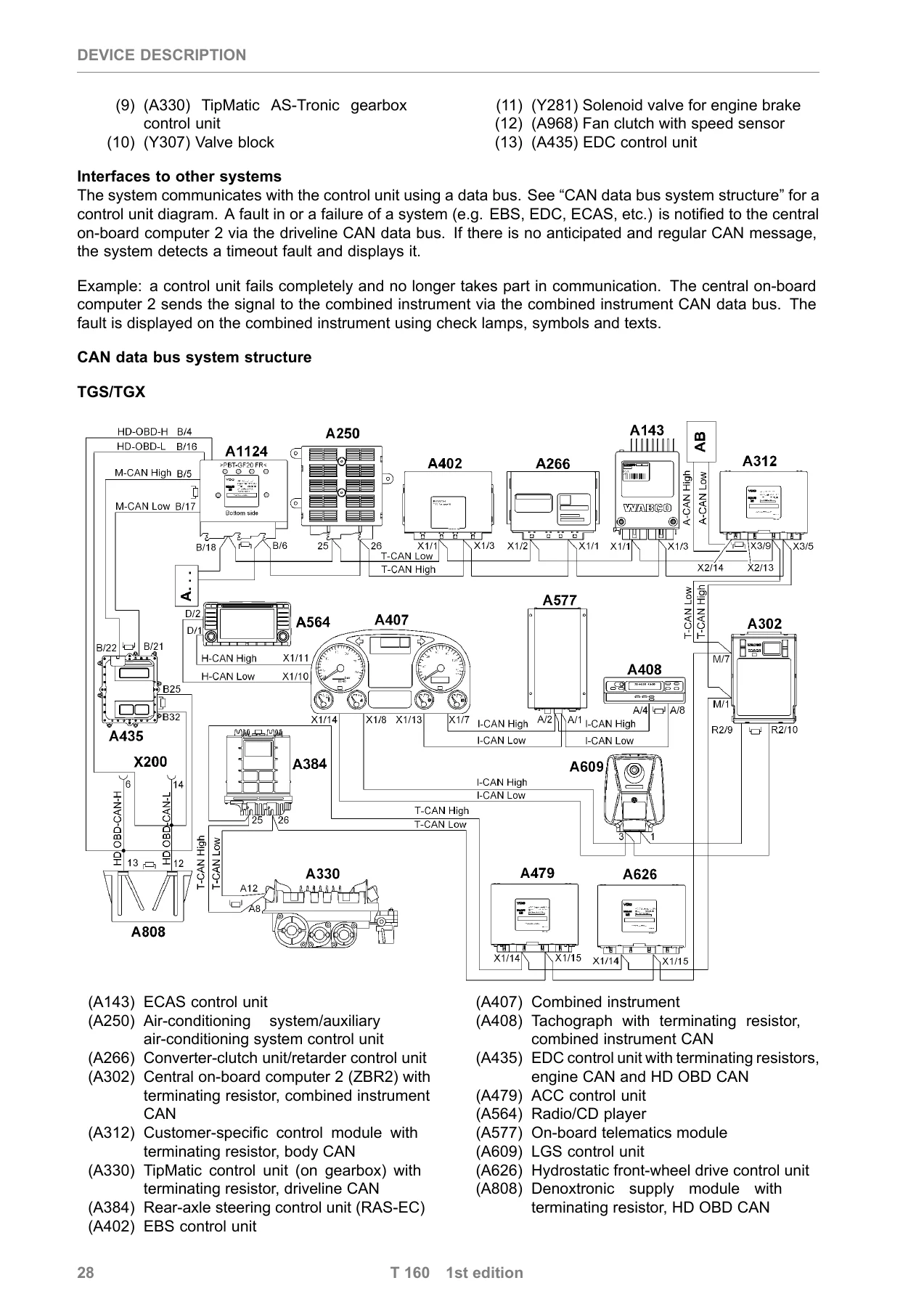
The Power Train Manager (A1124) replaces the earlier vehicle management computer (A403) as the primary driveline control unit. This chapter explains what changed — different electrical connections, a more powerful processor, larger memory — and warns that conversion between the A403 and A1124 is not possible (see SI 367102). It documents the interfaces to the other control units, the fault-notification path via the driveline CAN to the central on-board computer 2, and the timeout detection used when a system fails to send an expected CAN message. A complete TGS/TGX CAN architecture diagram shows the engine CAN (M-CAN), driveline CAN (T-CAN), combined instrument CAN (I-CAN), highline CAN (H-CAN), body manufacturer CAN (A-CAN), and Heavy Duty On-Board Diagnosis CAN (HD-OBD), including terminating resistors and the X200 diagnostic socket.
Functional Description — Power Train Manager, Pedal Unit, Fan Clutch, Multi-Function Steering Wheel, LIN Bus
The functional chapters cover the PTM’s cooling, engine warming, cruise control / maximum speed control, intermediate speed control, power take-off, data-saving, trend-data and maintenance-data functions; the 24 V supply from the central electrical system with fuses F1026 (terminal 30) and F1027 (terminal 15); the pin assignments for plug connectors A, B, C and VS; and the EOL programming that stores vehicle-specific parameters in the unit. The pedal unit chapter covers the accelerator (A410) with its two non-contact Hall sensors producing opposing PWM signals, the mechanical stop calibration values stored in flash memory, the idling-speed and kickdown thresholds, and the plausibility check against brake pedal position. The fan clutch chapter (A968) explains the PWM-driven solenoid and speed sensor, the fail-safe behaviour that fully engages the fan on supply-voltage loss, and the coolant / ambient / charge-air / retarder inputs that drive fan speed. The multi-function steering wheel chapter (A943) covers cruise control and menu operation on buttons 1–5 and 6–10. The LIN data bus chapter documents the 24 V single-wire, 9.6 kBit/s master/slave network linking the PTM to the multi-function steering wheel, stalk switches, gearbox DNR switch and combined instrument.
Description of Components
Component-level sections for the Power Train Manager (A1124), Accelerator (A410), Fan clutch with speed sensor (A968) and Multi-function steering wheel (A943), with installation locations, plug assignments, technical data and repair instructions. Includes the drain-bore detail (10 holes on the bottom of the PTM; at least one must remain open), the horizontal installation requirement, and the MAN-cats II menu paths used to identify, monitor and parametrise the unit.
Diagnostics
The diagnostics chapter opens with the HD-OBD diagnostic socket (X200) pinout per ISO 15031-3 and the communication-line vs. CAN-gateway access model used by MAN-cats II. It explains the malfunction indicator scheme — yellow for function/warning, red for fault, with red taking priority — the STOP safety indicator, the FMI (Failure Mode Identification) code table (FMI 0–13), the memory-status flags (No fault / Fault stored / Intermittent / Fault active and stored), the priority table for software versions R22 and R24, and the on-display fault-text structure with single-message, multi-message and value-message examples for trucks with and without the multi-function steering wheel. The break box (part 80.99641-6027 with 54-pin cable arms) and the Fluke ScopeMeter 123 procedure are documented, with the multi-function multimeter used for voltage and resistance steps.
SPN Diagnostic Code Description
Hundreds of SPN entries, each with its plain-text name, FMI diagnosis status, priority, display behaviour and (where applicable) cause and rectification. Coverage includes battery voltage (00168), CAN timeouts from EDC, EBS, ACC, ECAS, tachograph, gearbox, retarder, KSM and ZBR modules, accelerator channel 1 and 2 faults (05557 / 05558), clutch displacement sensor (05570), engine brake output (05581), main fan PWM output and fan speed sensor circuits (05583 / 05584 / 05585 / 05586), gearbox input speed sensor (05591 / 05592), oil level and oil temperature sensor (05608 / 05609 / 05610), exhaust gas back pressure sensor (05615 / 05616 / 05617), PTO1 and PTO2 outputs (05622 / 05624), range-change and splitter valve outputs (05690 / 05691 / 05692 / 05693 / 05694 / 05696), accelerator signal plausibility (05685), fan speed plausibility (05686), clutch servo outputs (05687 / 05688), and the internal-fault / EEPROM-replacement SPNs that trigger the STOP warning.
Test Step List
A full break-box test sequence with PTM pin designations, measuring-device polarity, setpoint values and units for digital inputs, analogue inputs, analogue outputs, PWM outputs, digital outputs, frequency inputs, CAN data bus lines (engine and driveline, ~120 Ω termination check) and the HD-OBD CAN pair (185/186). Includes resistance tables for the EDC resistor group used in torque-speed and maximum-speed limitation stages, ground continuity checks, and the specific conditions under which each measurement is taken (ignition OFF for resistance, ignition ON / engine running and vehicle stationary for voltage). Oscilloscope traces are provided for the gearbox input speed sensor (B368), immobiliser data line (A477), fan speed sensor (A968), oil level sensor (B270), accelerator PWM1 and PWM2, clutch displacement sensor (B362), engine and driveline CAN high/low, HD-OBD CAN high/low, and both LIN buses (64512 multi-function steering wheel / stalk switch / combined instrument, and 64515 DNR switch).
Additional Circuit Diagrams
Full-page circuit diagrams of the LIN data bus with and without multi-function steering wheel (PTM version, TGS/TGX) and a three-page Power Train Manager overview, complete with component legends, wire colours (bl, br, bl/wt, ye, wt/bl, wt/ye), crimp connectors, ground points and installation locations.
What You Can Do With This Manual
If you work on TGS or TGX trucks — in a workshop, at a dealer, on a fleet, or on your own — this is the document that lets you actually talk to the Power Train Manager instead of guessing at it. Read the SPN / FMI codes off MAN-cats II and this manual tells you what circuit, what sensor or what output they point to, whether the fault is priority 1 (STOP) or priority 5 (informational), and which diagnostic step to perform next. Trace a driveline CAN timeout back to the failed control unit and its terminating resistor. Verify the fan clutch hall supply, the gearbox input speed pickup, the clutch displacement sensor, and both accelerator PWM channels with a break box and a multimeter or ScopeMeter — using the exact setpoints and oscillator traces printed here. Confirm torque-speed and maximum-speed resistor-group stages from the resistance tables before condemning a switch. Check the LIN bus at 64512 and 64515 to see whether a fault is in the multi-function steering wheel, a stalk switch, the combined instrument or the DNR switch. And when you replace the PTM itself, use the correct parametrisation and EOL procedure rather than a generic configuration.
Getting the spec wrong on a TGS / TGX driveline is expensive — a mis-wired clutch servo, a fan clutch supply pinned to the wrong terminal, or a torque-speed limitation stage misread can wreck a gearbox or overheat an engine. The setpoints, pin tables, priority classifications and circuit diagrams in this T160 system description are the reference values, not a remembered average. For a truck that has to work, that difference matters.
IMAGES PREVIEW
Delivered as an instant PDF download. No shipping, no waiting, no CD drive. Read it on a laptop in the cab, on a tablet on the workshop floor, or print whichever pages you need and take them under the truck. Buy once, keep the file forever, and stop paying hourly for someone else to guess.
Reviews
There are no reviews yet.