
Manitou MRT 1432 1542 1635 1742 1850 2150 2540 Repair Manual – Multilingual PDF
Original price was: $49.95.$29.95Current price is: $29.95.
Comprehensive Manitou MRT Series repair manual covering MRT 1432, 1542, 1635, 1742, 1850, 2150 and 2540 machines, with engine service data, removal and installation procedures, hydrostatic transmission, axles and brakes, electrical systems, boom work, hydraulics, pressure checks and circuit diagrams.
Description
Manitou MRT Series Repair Manual
The Manitou MRT 1432 1542 1635 1742 1850 2150 2540 Repair Manual – Multilingual PDF brings together a large body of repair, adjustment, testing and component-service information for the MRT M Series. The material covers machine systems as well as detailed engine work, with model-specific procedures for the MRT 1432, MRT 1542, MRT 1635, MRT 1742, MRT 1850, MRT 2150 and MRT 2540 appearing throughout the transmission, electrical, boom and hydraulic sections. It is designed as a working technical reference for jobs that require more than routine operator information, including dismantling, installation, checking, calibration and system diagnosis.
File Details
- Manual type: Repair Manual
- Brand: Manitou
- Models: MRT 1432, MRT 1542, MRT 1635, MRT 1742, MRT 1850, MRT 2150, MRT 2540
- Language: Multilingual – English, French, German, Spanish and Italian are identified on the manual cover; many machine-system sections are presented in French, English and Spanish
- Page count: 1224 pages
- File format: PDF
Machine and Engine Coverage
This Manitou MRT repair manual is not limited to one subsystem. Its machine-specific material separates procedures where the MRT variants differ. Examples include hydrostatic motor removal for the MRT 1432, MRT 1542, MRT 1635 and MRT 1742 group and separate coverage for the MRT 1850, MRT 2150 and MRT 2540 group. Telescopic boom removal and installation is also divided by model group, while hydraulic component-location pages identify individual arrangements for MRT 1432 and 1635, MRT 1542, MRT 1742, and MRT 1850/2150/2540.
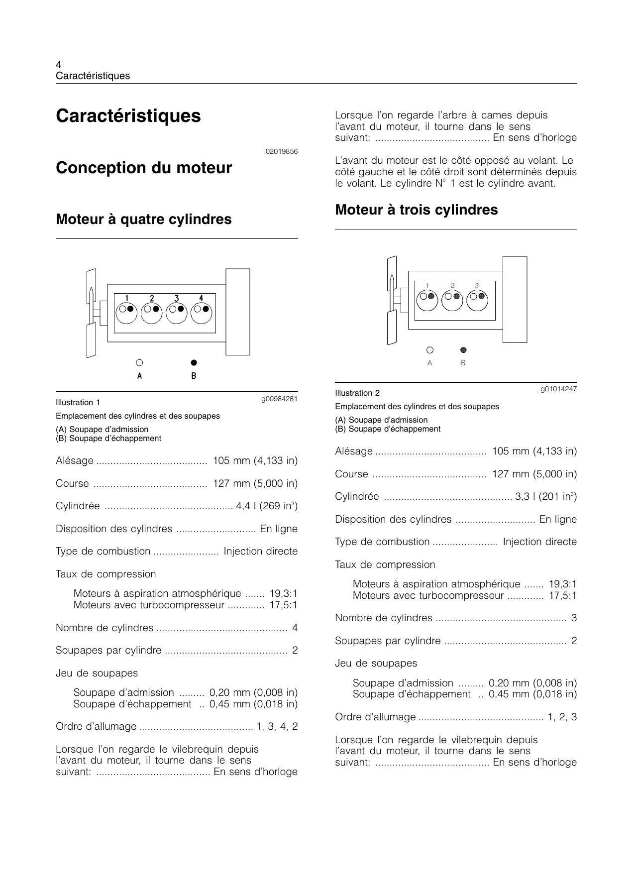
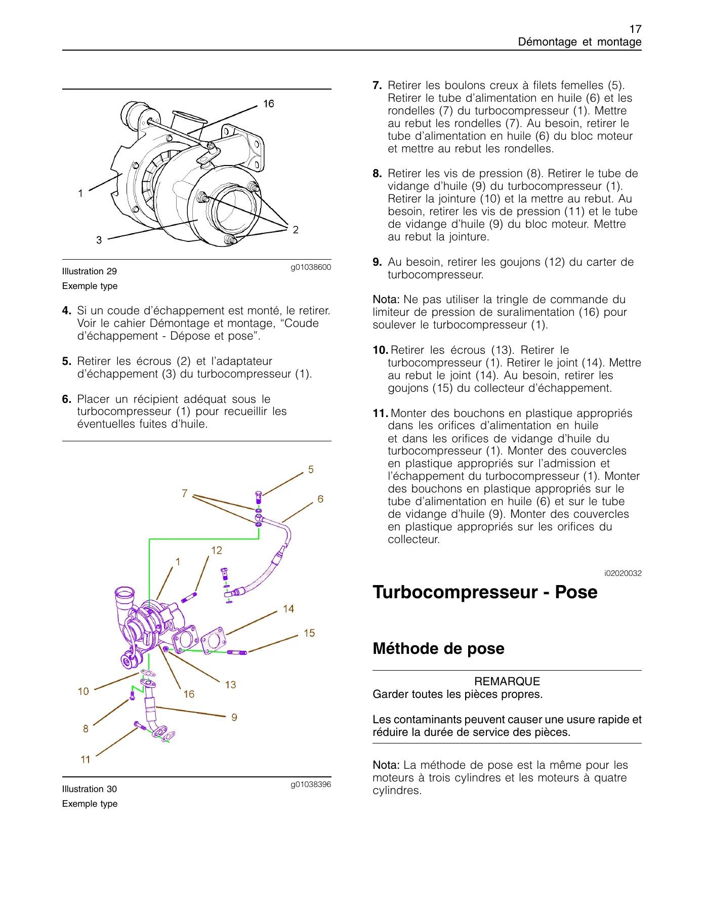
The engine material contains extensive specifications, dismantling and installation information, system-operation descriptions and test data. The manual identifies Perkins 1104C engine variants in the MRT transmission material, including 1104C.44T/1104C.44TA, and also contains detailed 1104 and 1103 engine sections. Engine coverage reaches well beyond basic tune-up information: fuel injection, cylinder head and valves, turbocharger, lubrication, cooling, crankshaft, pistons, connecting rods, timing gears, flywheel, alternator, starter and glow-plug information are all represented.
Repair Procedures, Checks and Adjustments
The depth of this Manitou MRT 1432 1542 1635 1742 1850 2150 2540 Repair Manual – Multilingual PDF is especially useful when a repair requires both the mechanical procedure and the values needed to complete the job correctly. Engine sections provide dimensional limits, clearances, tightening values and test figures alongside illustrated dismantling and assembly steps. Procedures include fuel-pump and injector work, cylinder-head and valve service, oil-pump and water-pump service, front gear-group timing, crankshaft seals, flywheel and housing work, and associated special-tool references.
The machine sections extend that approach to hydrostatic drive, axles, steering, brakes, stabilizers, boom functions and the main hydraulic system. Transmission material explains A4VG/A6VM hydrostatic operation, regulation and inching functions and includes check sheets and adjustment procedures. Hydraulic pages cover pressure checking at the main Danfoss valve system, boom extension and tilting circuits, turret rotation, steering and stabilizer circuits, with model-specific pressure-check locations and diagrams. This makes the MRT Series repair manual useful for tracing a fault from a symptom or test point through to the component that must be adjusted or removed.
Electrical and Control-System Reference
Electrical coverage includes starter and charging information, fuse and relay functions, machine wiring, control inputs, solenoid valves, stabilizer controls, boom work lights, travel circuits, anti-tipping related circuits and radio-control connections. Separate electrical-system material is shown for the MRT 1432-1635 M Series and for the MRT 1542-1742-1850-2150-2540 M Series, with wiring tables and diagrams that identify connectors, relays, fuses, switches, sensors and control functions. These sections are valuable when a mechanical fault has an electrical interlock, sensor, relay or solenoid component.
Chapters Covered
- MOTORISATION
- Caracteristiques moteur
- Démontage et montage Partie 1
- Démontage et montage Partie 2
- Démontage et montage Partie 3
- Moteur : Fonctionnement des systèmes
- Moteur : Circuit de carburant
- Moteur : Circuit d’admission et d’échappement d’air
- Moteur : Circuit de graissage
- Moteur : Circuit de refroidissement
- Moteur : Moteur de base
- Moteur : Circuit électrique
- GÉNÉRALITÉS, CARACTÉRISTIQUES ET SÉCURITÉS
- Moteur : Fonctionnement des systèmes
- Démontage pont 212 (généralités)
- SCHEMAS ELECTRIQUE
- ELECTRICITE
- Moteur : Fonctionnement des systèmes
- Moteur : Circuit électrique
- Radio commande
- SCHEMAS ELECTRIQUE
- CABLAGES TABLEAU À POUSSOIRS NACELLE
- Description du contrôle d’état de charge
- consultation des écrans du contrôleur d’état de charge
- calibrage
- schéma 3B6
- TRANSMISSION
- DÉPOSE DU PONT AVANT-ARRIÈRE ET DU MOTEUR HYDROSTATIQUE
- Démontage boite transfert 357
- Démontage pont 212 – arbres à cardan
- Option : boite de transfert – 602
- Dépose du moteur hydrostatique by MRT model group
- FONCTIONNEMENT (REGLAGES) DE LA TRANSMISSION
- PONT – ESSIEU
- Démontage pont 212 (généralités)
- Contrôle d’usure et remplacement des disques de freins
- Dépose et repose du pivot de direction
- Dépose et repose du réducteur de roue
- Dépose et repose du vérin de direction
- Réglage des butées de direction
- Dépose, repose, démontage et remontage du différentiel
- Dépose et repose du couple conique
- Outils spéciaux
- Recherche de pannes
- Options de différentiel et blocage hydraulique
- FREIN
- Contrôle d’usure et remplacement des disques de freins
- Frein à main mécanique
- Frein hydraulique externe
- Frein en tambour en entrée
- Frein négatif hydraulique
- PURGE DU SYSTEME DE FREINAGE
- OPTIONS – ACCESSOIRES
- Frein hydraulique externe
- Frein en tambour en entrée
- Blocage différentiel à commande hydraulique
- Radio commande
- FLECHE
- Dépose et repose de la flèche télescopique MRT 1432 – 1542 – 1635
- Dépose et repose de la flèche télescopique MRT 1742 – 1850 – 2150 – 2540
- Position des composants hydrauliques MRT 1432 – 1635 (400°)
- HYDRAULIQUE
- Démontage du réservoir
- Démontage et remontage collecteur hydraulique de rotation
- Dépose et repose du reducteur
- Vérins de stabilisateurs by MRT model group
- Normes générales démontage vérins
- Procédure purge air vérin commande accelerateur
- Contrôle des préssions
- circuits hydrauliques 400° and 360°
- Position des composants hydrauliques by MRT model
Taken as a whole, the chapter structure links component-level repair with system operation. A technician can move from engine specifications and removal procedures to transmission settings, axle and brake work, electrical diagrams, boom removal, cylinder service and hydraulic pressure checks without relying on a single narrow section of the document. Model-specific references throughout the machine chapters help distinguish which procedure or arrangement applies to a particular MRT version.
Illustrations, Diagrams and Service Data
The manual makes extensive use of component illustrations, exploded views, wiring diagrams, hydraulic schematics and numbered service drawings. Engine pages show parts such as injection pumps, cylinder-head components, crankshafts, pistons, oil pumps, water pumps and timing gears together with measurements and tightening sequences. Machine-system pages add hydrostatic transmission diagrams, electrical schematics, hydraulic layouts and component positions. The combination is particularly useful during disassembly and reassembly, where the relationship between parts, ports, connectors and fasteners matters as much as the written procedure.
Repair Capability and PDF Delivery
The Manitou MRT 1432 1542 1635 1742 1850 2150 2540 Repair Manual – Multilingual PDF supports substantial workshop work: engine diagnosis and overhaul procedures, fuel-system service, hydrostatic transmission checks and adjustments, axle and brake repairs, electrical fault tracing, telescopic-boom removal and installation, stabilizer-cylinder work, hydraulic pressure testing and circuit reference. Using the specified procedures, tightening data, measurements, diagrams and model-specific instructions helps reduce guesswork when parts are being inspected, adjusted or reassembled. After payment, the manual is supplied as an instant PDF download with no shipping required. It can be opened on a compatible phone, tablet or computer and printed whenever a paper working copy is useful in the workshop.
Reviews
There are no reviews yet.