
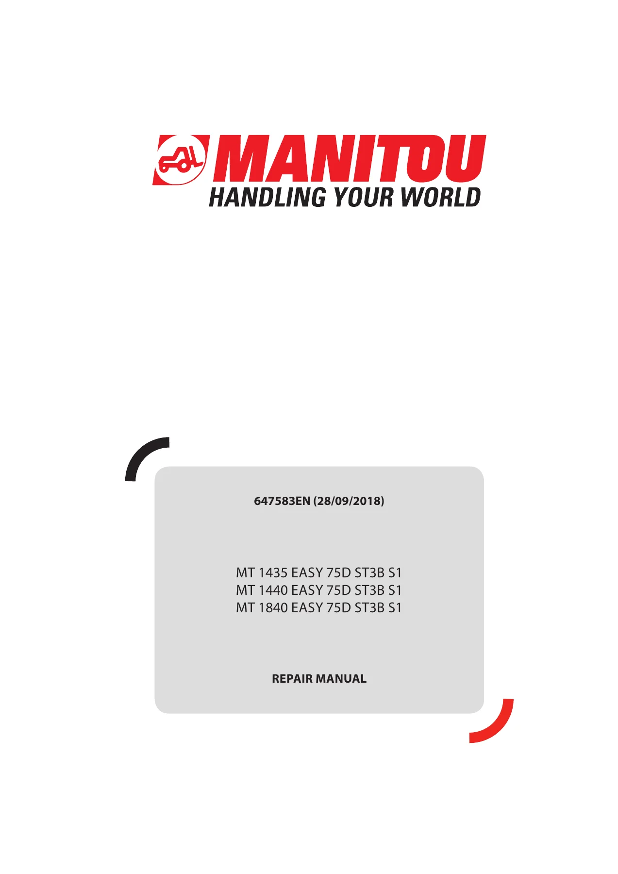
Manitou MT 1435 1440 1840 EASY 75D ST3B S1 Repair Manual 647583EN
Original price was: $34.95.$21.95Current price is: $21.95.
Complete workshop repair manual for Manitou MT 1435 EASY, MT 1440 EASY and MT 1840 EASY telescopic handlers with 75D ST3B S1 engine. Covers engine, transmission, axles, brakes, boom, hydraulics, electrics and cab. 647583EN.
Description
Manitou MT 1435 1440 1840 EASY 75D ST3B S1 Repair Manual
The Manitou MT 1435 1440 1840 EASY 75D ST3B S1 Repair Manual is the full workshop document (reference 647583EN) covering the three Easy-series telescopic handlers fitted with the 75D ST3B S1 engine. It is the same manual a Manitou-trained technician works from in the workshop, grouped by system so every procedure, tightening torque and specification sits alongside the diagrams and illustrations that support it.
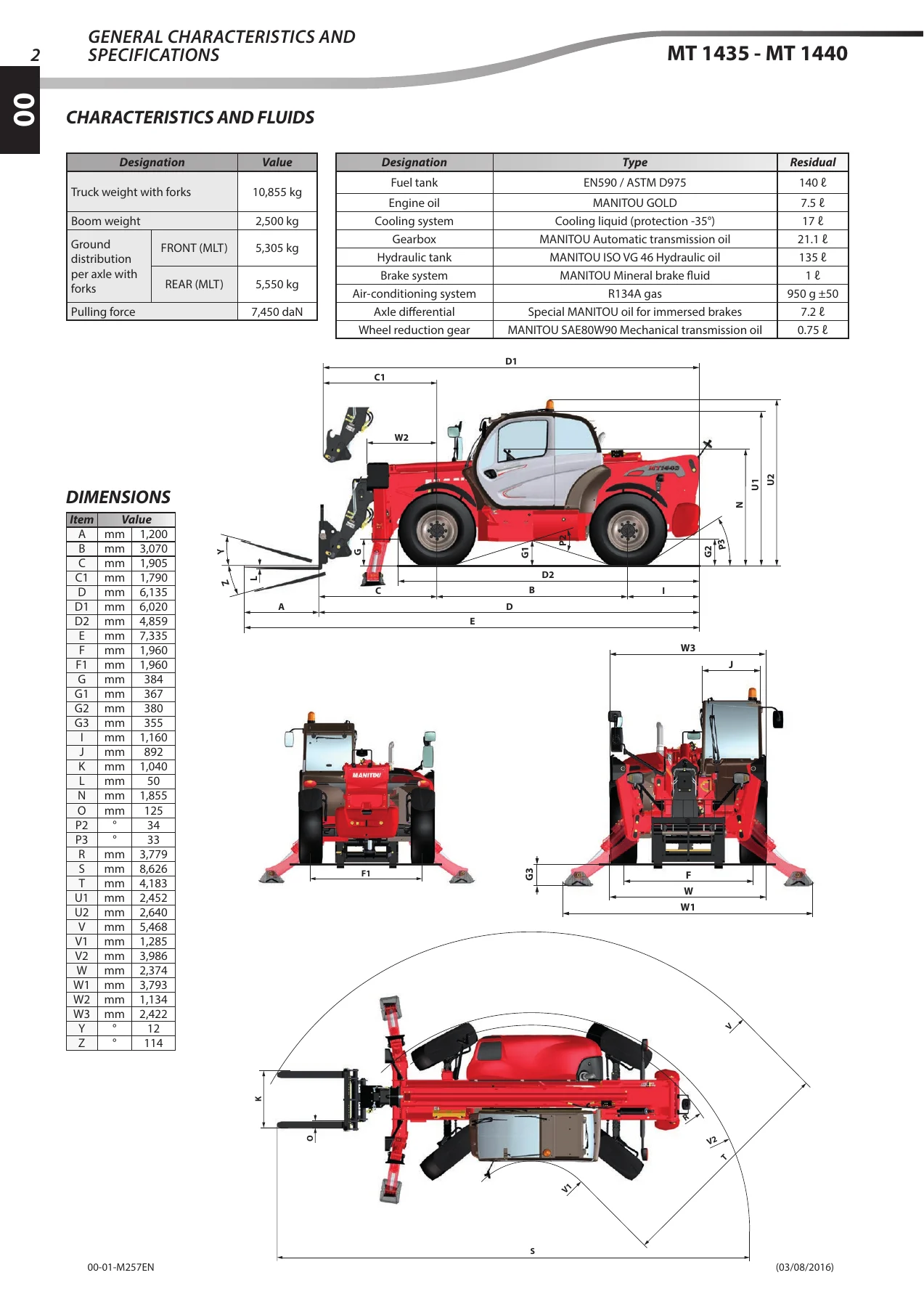
The document is organised into numbered groups – 00, 10, 20, 30, 40, 50, 70, 80, 85, 90 and 110 – each of which opens with its own characteristic values, tightening torques and safety instructions before moving into removal, refitting and adjustment.
File Details
- Manual type: Repair Manual (workshop service manual)
- Brand: Manitou (MANITOU BF S.A.)
- Models covered: MT 1435 EASY 75D ST3B S1, MT 1440 EASY 75D ST3B S1, MT 1840 EASY 75D ST3B S1
- Document number: 647583EN
- Edition / date: 28/09/2018 (first issue 15/05/2016, updates 23/04/2018 and 28/09/2018)
- Language: English
- Format: PDF
Chapters Covered
The manual follows Manitou’s group numbering, and each group opens with a chapter list of its own:
- 00 – General instructions and safety notice: preamble, maintenance position, rules for maintenance, standard tightening torques, general location and identification plates
- 10 – Engine: characteristics and fluids, dimensions, engine tightening torques, ventilation management (function, principle of operation, schematic and hydraulic diagrams, ventilation control conditions), air intake circuit and EGR, lubrication circuit, cooling system, fuel circuit, engine components location, water cooling system, hydraulic ventilation system, diesel fuel circuit, fuel injection circuit, EGR circuit, starter removal, drive belt removal, alternator removal, fan engine removal, engine ECU removal and refit, catalytic converter removal and refit, cooler removal, engine removal, fault table, error indicator lamp, ignition switching test, start-up conditions, lack of power, injection code, fan check points, engine error codes, electronic tension meter, additional engine tools
- 20 – Transmission: mechanical transmission (standard) drive train, operation overview, gearbox port locations, neutral/forward/reverse schematic diagrams, transmission system, cooling system, pressure test ports and values, transmission assembly tightening torques, blocking 4th gear, gearbox removal, basic manometer set, digital manometer set, 50 mm machined socket
- 30 – Axle: axle control and adjustment, axle troubleshooting, specific axle tooling
- 40 – Brake: service brake and parking brake characteristics, brake schematic diagrams, brake components location, pedal system stop adjustment, bleeding procedure, freewheel and towing, parking brake adjustment, brake pads, parking brake unit, hydraulic brake bleed valve, parking brake bleeder harness
- 50 – Boom: Triplex (MT 14 m) and Quadruplex (MT 18 m) boom overview, boom weights, chain wear inspection (outer and inner chains), dismantling chain boom components, hydraulic kit removal, telescope T2+T3 assembly removal, telescope T3 removal, reassembly, chain tension presets, chain tension checking and setting, hydraulic kit refit, hose tension adjustment, channel lever, hose routing support tool, hose tension adjustment gauge, chain checking gauge
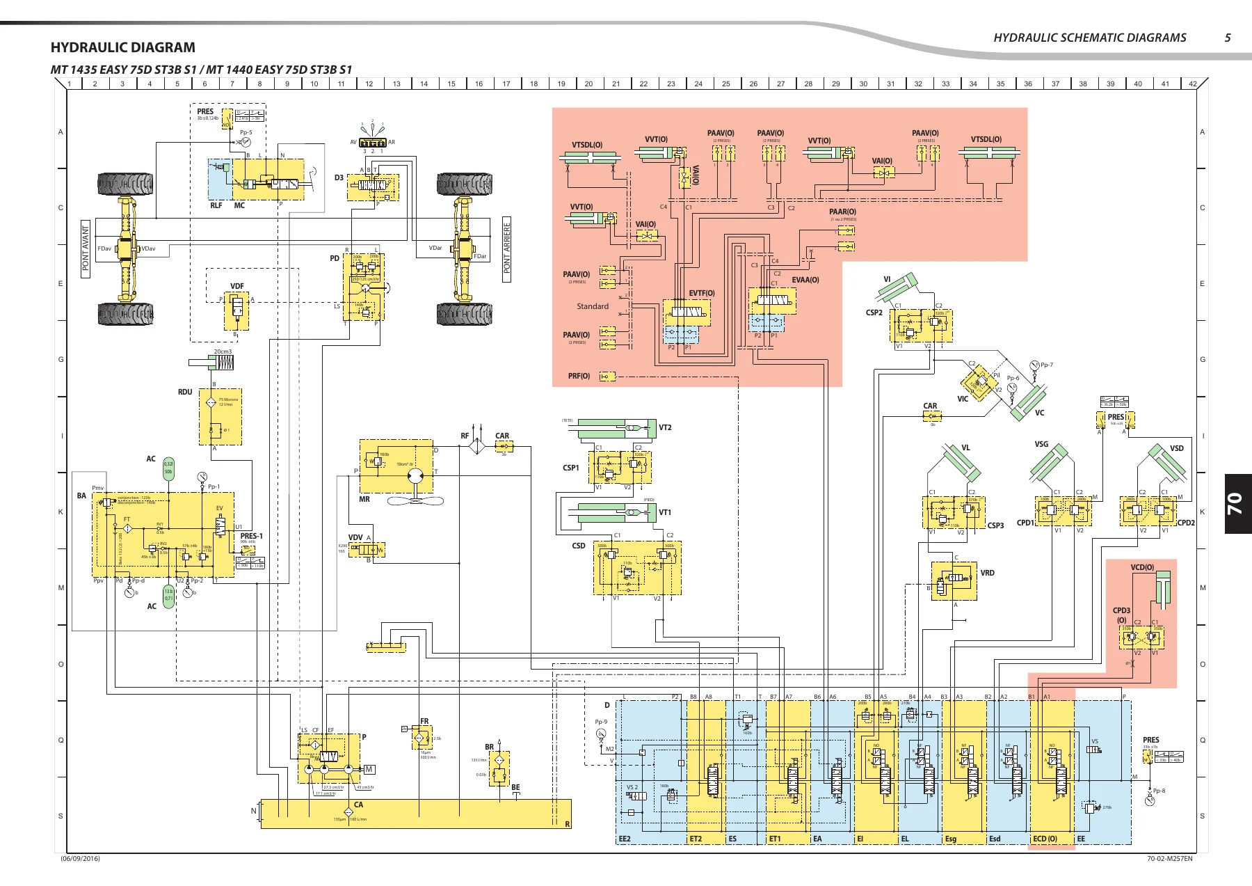
- 70 – Hydraulic: hydraulic characteristics, priority flow divider (DDP), master cylinder, orbitrol, double counterbalance valve, double safety valve, complete electrovalve, compensating cylinder isolation valve, TX telescope double counterbalance valve, Danfoss PVG, hydraulic schematic diagrams, hydraulic components location, pressure test ports and values, bleeding procedures, main distributor tightening torques, oil tank removal/refit, mechanically controlled distributor removal/refit, basic and digital manometer sets
- 80 – Electricity: fuses and relays (engine compartment BF1, cab BF3), shunt bar, connectors, ECU inputs/outputs (engine ECU, Manimux Cluster MC, Manimux Power MP1, MP2, options ECU), data sheets for electrical components, electrical schematic diagrams (diagrams 1 to 11 covering engine start, CAN/OBD, transmission, hydraulic movement, sensors, lighting, options, heating/air-conditioning, rear hydraulic two-way, TDF EV, fan regulation), electrical components location (2D and 3D harness routing), cluster menu architecture, calibration menu, replacement of ECUs, boom angle sensor adjustment, strain gauge refit, input/output states, error codes (DTC) for MC, MP1, MP2 and ENG, diagnostic tools, breakout boxes, electrovalve adapter
- 85 – Driver’s cab: electric window and engine removal, lower dashboard lining removal, cab refit on silent blocks, electrical connection, hydraulic connection
- 90 – Frame – Bodywork
- 110 – Options – Attachments: air-conditioning option – characteristics and specifications, description of operation, operating principle, evaporator temperature probe characteristics, air-conditioning locations and tightening torques, HVAC interior and exterior components, condenser components, general check points, assembly instructions for the air-conditioning circuit, safety measures for handling R134A, refrigerant fluid load, evaporator temperature sensor control, air-conditioning belt removal and refit, temperature troubleshooting, abnormal noise, unpleasant smell
Grouped together, these chapters give a technician the complete service picture for the MT 1435, MT 1440 and MT 1840 EASY: engine and after-treatment repair, gearbox and transmission shaft work, axle and brake servicing, the whole boom and chain assembly, the priority flow divider and valve bank hydraulics, full electrical diagnostics with connector pin-outs and DTC tables, cab removal and refit, and the optional air-conditioning system.
What This Manual Lets You Do
With the Manitou MT 1435 1440 1840 EASY 75D ST3B S1 Repair Manual on hand, you can carry out a full range of jobs on these three telehandlers: remove and refit the engine, gearbox, axles, brakes, boom telescopes and hydraulic kit; bleed the brake and compensating circuits; set boom chain tensions using the manufacturer’s preset dimensions; read and clear fault codes through the cluster menus or the PAD diagnostic tool; adjust the boom angle sensor; and service the air-conditioning system including the evaporator temperature probe.
Having the correct specification matters on machines like these. Torque values, pressure test port readings, chain preset dimensions and calibration steps are the difference between a repair that holds and a repair that comes back. The manual prints each of these next to the procedure it belongs to, so you are working to Manitou’s numbers, not guesswork.
IMAGES PREVIEW
Delivery is instant via PDF download – no shipping, no waiting. The file opens on any device and pages can be printed as needed for the workshop.


Reviews
There are no reviews yet.