
Manitou MT 732 MT 932 MLT 630 634 731 Turbo Series B-E2 Electrical Diagrams Manual – Group 80 PDF
Original price was: $74.95.$49.95Current price is: $49.95.
432-page Manitou Group 80 electrical diagrams manual for MT 732, MT 932, MLT 630, MLT 634 and MLT 731 Turbo Series B-E2 machines. Covers wiring diagrams, fuses, relays, connectors, component locations, diagnostics and calibration.
Description
Manitou MT 732, MT 932 and MLT 630 / 634 / 731 Turbo Series B-E2 Electrical Diagrams Manual – Group 80
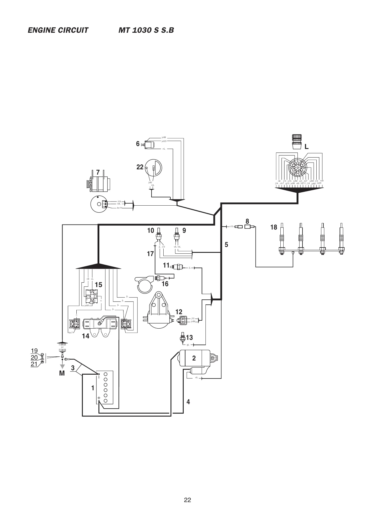
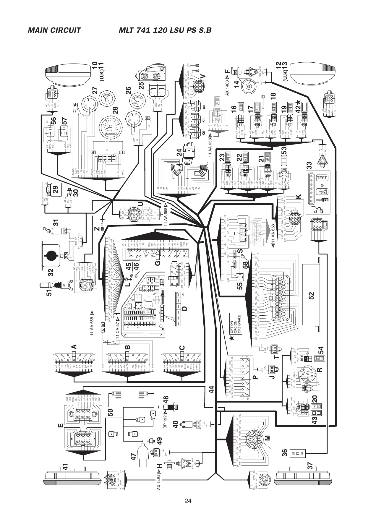
This 432-page Manitou electrical diagrams manual covers the MT 732, MT 932, MLT 630, MLT 634 and MLT 731 Turbo Series B-E2 machines, with additional electrical diagram sections for later series such as MLT 735, MLT 741, MLT 742, MT 1030 S and MLT 1035 L. Group 80 Electricity is the core topic: you get the wiring diagrams, fuse and relay layouts, connector views, component identification and diagnostic/calibration information needed to trace circuits, diagnose electrical faults and understand the electrical architecture of these lift trucks. The file is built from original electrical diagram pages and includes both circuit schematics and the supporting legends, colour codes, fuse ratings and relay functions that make those schematics usable in the workshop.
File Details
- Manual type: Electrical diagrams / electric circuits manual
- Brand: Manitou
- Primary models: MT 732 Série B-E2, MT 932 Série B-E2, MLT 630 Turbo Série B-E2, MLT 630 120 LSU Série B-E2, MLT 634 Turbo LSU Série B-E2, MLT 634 120 LSU Série B-E2, MLT 634 120 LSU POWERSHIFT Série B-E2, MLT 731 Turbo Série B-E2, MLT 731 Turbo LSU Série B-E2
- Additional series shown: MLT 735, MLT 741, MLT 742, MT 1030 S, MLT 1035 L, plus C-E2, 2-E2 and 3-E2 sections
- Language: English text; diagram labels include French, German, Spanish and Italian terms
- Page count: 432
- File format: PDF
- Group: Group 80 Electricity
- Document numbers include: 80-6-10-M94 EN, 80-6-10-M110 EN, 80-6-253956 EN, 80-6-268674 EN, 80-6-268675 EN, 80-6-268677 EN, 80-6-268678 EN, 80-6-268679 EN, 80-6-268682 EN, 80-6-268683 EN
- Dates shown: Editions dated from 2004 through 2007, including 26/01/2005, 06/06/2006, 26/04/2007 and 15/11/2007
Chapters Covered
- ELECTRIC DIAGRAM
- PRINCIPLE ELECTRIC CIRCUIT
- COLOUR CODING
- CONNECTOR
- ELECTRICS COMPONENTS
- FUSES
- LOCATION AND DESCRIPTION OF THE DISK
- ACCESS PANEL FUSES AND RELAYS
- RELAY BRACKET MARK
- OPERATION: PROGRESSIVITY MODULE
- JSM HAND CONTROLLER UNIT OPERATION
- VERIFICATION OF THE JOYSTICK
- FORCED OPERATION FONCTIONING
- OPERATION OF ARM SUSPENSION CRC
- OPERATION: POWER REGULATION
- OPERATING AND SETTING OF THE LONGITUDINAL STABILITY ALARM
- CALIBRATOR BB3
- ELECTRIC CIRCUIT READING PRINCIPLE
- HYDRAULIC CIRCUITS within the arm suspension and progressivity sections
Electric Diagrams by Machine Series
The heart of this manual is the model-by-model electric diagram coverage. Separate diagram sets are provided for the MT 732 and MT 932 Série B-E2, the MLT 630 Turbo and MLT 630 120 LSU Série B-E2, the MLT 634 Turbo LSU and MLT 634 120 LSU Série B-E2, the MLT 634 120 LSU POWERSHIFT Série B-E2, and the MLT 731 Turbo and MLT 731 Turbo LSU Série B-E2. Later in the file you will also find electric diagram sections for MLT 735, MLT 741, MLT 742, MT 1030 S and MLT 1035 L variants. These pages show the electrical connections between the battery, starter, alternator, preheating system, instrument panel, lighting, windscreen wipers, transmission cut-off, forward and reverse electrovalves, hydraulic controls and optional equipment. The diagrams use standard connector references and colour-coded wire labels so you can follow a circuit from the fuse box or relay plate through to the component or earth point.
Principle Electric Circuit, Colour Coding and Connectors
Each diagram set is supported by a principle electric circuit section and a colour coding key. The colour coding chart identifies wire colours such as bc for white, bl for blue, g for grey, j for yellow, jvt for yellow/green, m for brown, n for black, o for orange, r for red, ro for pink, vt for green and v for purple. Connector definitions explain what each multi-pin connector does, including fuse box and relay connections, engine box connections, light switch, heating ventilation, air conditioning, cab, front windscreen wiper, overload strain gauge and diagnostic sockets. This is the information that turns a dense schematic into a practical fault-finding tool, because you can identify the correct pin, wire colour and component before you start testing.
Fuses, Relays and Access Panel Layouts
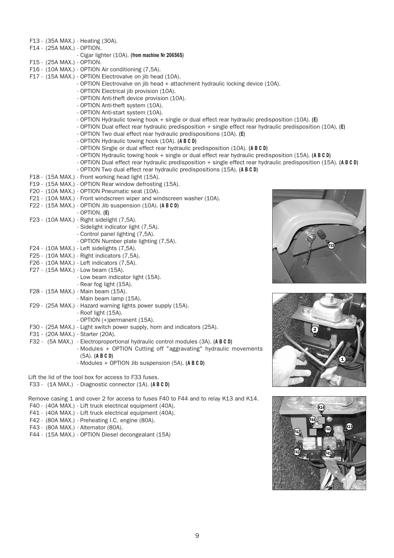
The manual includes detailed fuse and relay access panel information. It lists relay bracket marks, relay functions and fuse ratings for the different machine groups. Typical relay references include K0 for air conditioning, K1 for transmission cut-off or joystick functions depending on model, K2 for transmission cut-off, K3 and K4 for reverse and forward gear relays, K5 for buzzer, K6 for jib head electrovalve or electrical jib provision, K7 for hydraulic movements cut-off, K8 for starting safety, K9 for flasher unit, K10 and K11 for jib suspension, K13 for preheating, K15 for proportional hydraulic control supply, K16 for preheating, K17 for indicator light module and K18 for transmission cut-off or towing functions depending on the series. Fuse tables cover F1 through F44, with ratings such as 5A, 7.5A, 10A, 15A, 20A, 25A, 30A, 40A and 80A, and identify what each fuse protects. You will find access panel layouts for the cab, engine box and tool box areas, including the location of high-current fuses F40 to F44.
Component Location, Diagnostics and Calibration
The electrical component descriptions cover the major items you will meet on these machines: indicator lights, stop lights, position lights, low beam, main beam, working headlights, working tail lights, revolving light, reverse lights, roof light, windscreen wiper motors, windscreen washer, sound alarm, fuel pump, fuel level sensor, engine water temperature sensor, engine oil pressure switch, brake fluid switch, air filter clogging switch, hydraulic return filter clogging switch, transmission oil pressure and temperature switches, handbrake switch, overload strain gauge, forward and reverse electrovalves, cold start-up electrovalve, stabilizer electrovalves, hydraulic movements cut-off electrovalve and proportional electrovalves. Diagnostic sections include the BB3 calibrator procedure for RC2-1 and RC2-2 electronic units, with menus for parameter setting, accelerator pedal angle sensor configuration, diesel characteristic learning, error code reading, dynamic monitoring and reset procedures. There is also guidance on checking the joystick, the progressivity module, the forced operation option and the longitudinal stability alarm strain gauge, including expected impedance values and connector pin functions.
Joystick, Progressivity, Power Regulation and Arm Suspension
For machines with proportional hydraulic controls, the manual explains the 4TH5 hydraulic pilot control unit, the JSM multifunctional hand controller, the progressivity module, internal joystick connections, wire functions, test device connections and output checks for proportional solenoid valves. Power regulation sections cover the A10VO EK1 pump controlled by the RC2 microcontroller, describing the proportional solenoid valve EK1, accelerator position sensor, engine speed sensor at alternator terminal W and the electronic unit. The arm suspension CRC section explains the hydraulic and electrical circuits for jib suspension, including the balancing valve, accumulator, pressure switches, position switches and relays K10, K11 and K12, plus the operating logic that deactivates suspension when the machine moves beyond the set height or when aggravating hydraulic movements are used.
Longitudinal Stability Alarm and Electrical Measurements
The final part of the file covers the longitudinal stability alarm. It explains the operator and unit display sequence, LED and buzzer behaviour, setting for position 0 and position MAX, the test and stop buzzer buttons, and the inspection procedure for the strain gauge. Connector engineering is given for the strain gauge, including power supply, measurement, PT100 and shielding wires. Electrical inspection values are listed, such as expected impedance between A+ and A- of 300 to 400 ohms, the same range between M+ and M-, and the PT100 value calculated as 101 ohms plus 0.39 times the gauge temperature. These values help you confirm whether the stability alarm sensor and its wiring are within specification before you adjust or replace components.
Why This Electrical Diagrams Manual Matters
Electrical faults on Manitou MT and MLT lift trucks can stop a machine just as quickly as a hydraulic or mechanical failure. Without the correct diagram, you can lose hours chasing a broken wire, a failed relay, a poor earth or a misidentified fuse. This Manitou Group 80 electrical diagrams manual gives you the circuit paths, connector numbers, wire colours, fuse ratings and relay functions for the MT 732, MT 932, MLT 630, MLT 634 and MLT 731 Turbo Series B-E2 families, plus useful later-series coverage. It supports real workshop tasks: tracing a no-start condition, diagnosing lighting faults, checking transmission cut-off circuits, testing forward and reverse electrovalves, verifying proportional joystick signals, setting the BB3 calibrator, checking the progressivity module and inspecting the longitudinal stability alarm. The diagnostic and calibration sections are especially valuable when you need to confirm sensor voltages, solenoid currents or strain gauge impedance before replacing parts.
IMAGES PREVIEW
Instant PDF Delivery
This is a downloadable PDF manual, not a physical book. After checkout, you can open it on a laptop, tablet or smartphone, search through the 432 pages and print only the diagrams or tables you need for the job. Keep it in the workshop, load it on a diagnostic laptop or print a circuit page to take out to the machine. With instant delivery and no shipping, you can be reading the wiring diagram for your MT 732, MT 932, MLT 630, MLT 634 or MLT 731 Turbo Series B-E2 within minutes.

Reviews
There are no reviews yet.