Manitowoc Crane 3900 Parts Manual SN 39129 PDF
$28.95
The Manitowoc Traditional Crane 3900 Parts Manual (SN 39129) in PDF format is a crucial guide for maintenance. Featuring detailed diagrams and genuine part details, it streamlines repairs and servicing for the Manitowoc Traditional Crane 3900 with serial number 39129.
Description
Manitowoc Traditional Crane 3900 Parts Manual SN 39129 – PDF DOWNLOAD
FILE DETAILS:
Manitowoc Traditional Crane 3900 Parts Manual SN 39129 – PDF DOWNLOAD
Language : English
Pages :240
Downloadable : Yes
File Type : PDF
Customer Support: [email protected]
IMAGES PREVIEW OF THE MANUAL:
TABLE OF CONTENTS:
Manitowoc Traditional Crane 3900 Parts Manual SN 39129 – PDF DOWNLOAD
General 1
Inspection Intervals 1
Inspection Guidelines 3
Replacement Criteria 3
Dents 3
Gradual and Sweeping Bends 3
Corrosion and Abrasion 5
Kinks 5
Cracks and Breaks 5
Chord Straightness 7
Ordering Lacings 7
Assistance 7
Boom or Jib Identification 7
A Ordering Lacings from Lacing Drawings 8
B Ordering Lacings without Lacing Drawings 9
Repair Procedure 10
Extent of Repair 10
Preparing for Welding 10
Repair Facility 10
Outdoor Repairs 10
General Equipment Requirements 10
Repair Procedures and Processes 11
End Lacing Replacement 12
End Lacing Replacement on an Insert (Angle and
Tubular Chords) 13
End Lacing Replacement on Tapered Sections
(Tubular Chords) 13
Lacing Removal — Boom Section with a Bent or Bowed
Chord Member 13
Determining Amount of Stick Electrode Needed 14
Inspection Checklist 19
Record Keeping 19
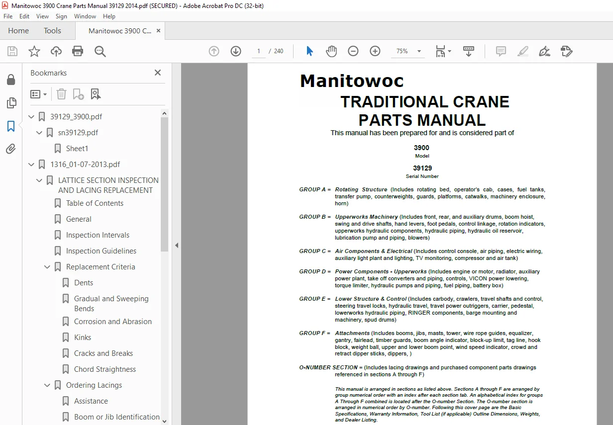
GROUP A = Rotating Structure (Includes rotating bed, operator’s cab, cases, fuel tanks,
transfer pump, counterweights, guards, platforms, catwalks, machinery enclosure,
horn)
GROUP B = Upperworks Machinery (Includes front, rear, and auxiliary drums, boom hoist,
swing and drive shafts, hand levers, foot pedals, control linkage, rotation indicators,
upperworks hydraulic components, hydraulic piping, hydraulic oil reservoir,
lubrication pump and piping, blowers)
GROUP C = Air Components & Electrical (Includes control console, air piping, electric wiring,
auxiliary light plant and lighting, TV monitoring, compressor and air tank)
GROUP D = Power Components – Upperworks (Includes engine or motor, radiator, auxiliary
power plant, take off converters and piping, controls, VICON power lowering,
torque limiter, hydraulic pumps and piping, fuel piping, battery box)
GROUP E = Lower Structure & Control (Includes carbody, crawlers, travel shafts and control,
steering travel locks, hydraulic travel, travel power outriggers, carrier, pedestal,
lowerworks hydraulic piping, RINGER components, barge mounting and
machinery, spud drums)
GROUP F = Attachments (Includes booms, jibs, masts, tower, wire rope guides, equalizer,
gantry, fairlead, timber guards, boom angle indicator, block-up limit, tag line, hook
block, weight ball, upper and lower boom point, wind speed indicator, crowd and
retract dipper sticks, dippers, )
O-NUMBER SECTION = (Includes lacing drawings and purchased component parts drawings
referenced in sections A through F)
This manual is arranged in sections as listed above. Sections A through F are arranged by
group numerical order with an index after each section tab. An alphabetical index for groups
A Through F combined is located after the O-number Section. The O-number section is
arranged in numerical order by O-number. Following this cover page are the Basic
Specifications, Warranty Information, Tool List (if applicable) Outline Dimensions, Weights,
and Dealer Listing.
S.M