Manitowoc Grove 600D Series Crane Operating Manual PDF
$27.95
Description
Manitowoc Grove 600D Series Articulating & Telescoping Crane Operating Manual – PDF DOWNLOAD
FILE DETAILS:
Manitowoc Grove 600D Series Articulating & Telescoping Crane Operating Manual – PDF DOWNLOAD
Language : English
Pages : 174
Downloadable : Yes
File Type : PDF
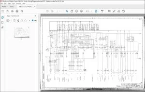
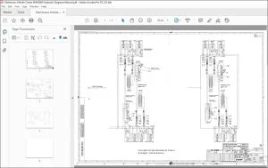
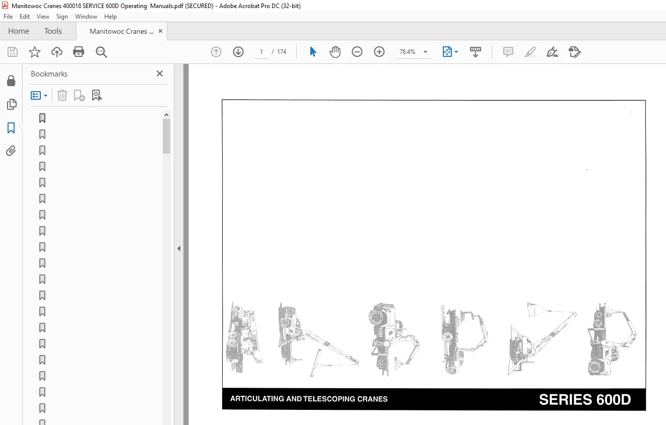
IMAGES PREVIEW OF THE MANUAL:
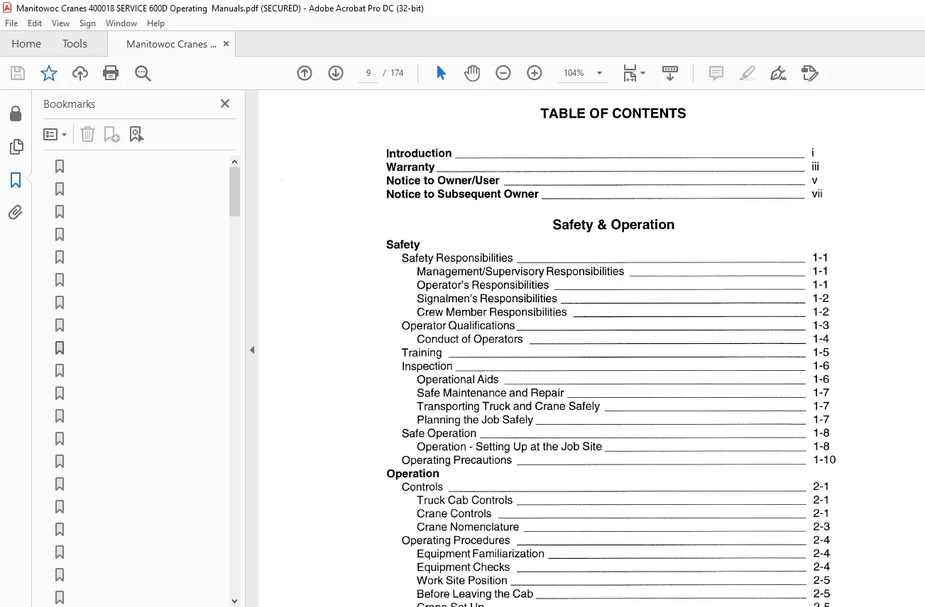
TABLE OF CONTENTS:
Manitowoc Grove 600D Series Articulating & Telescoping Crane Operating Manual – PDF DOWNLOAD
Introduction
Warranty
Notice to Owner/User
Notice to Subsequent Owner
Safety & Operation
Safety
Safety Responsibilities
Management/Supervisory Responsibilities
Operator’s Responsibilities
Signalmen’s Responsibilities
Crew Member Responsibilities
Operator Qualifications
Conduct of Operators
Training
Inspection
Operational Aids
Safe Maintenance and Repair
Transporting Truck and Crane Safely
Planning the Job Safely
Safe Operation
Operation – Setting Up at the Job Site
Operating Precautions
Operation
Controls 2-1
Truck Cab Controls 2-1
Crane Controls 2-1
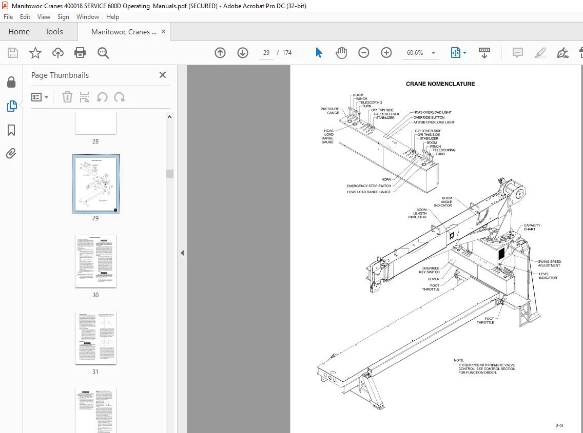
Crane Nomenclature 2-3
Operating Procedures 2-4
Equipment Familiarization 2-4
Equipment Checks 2-4
Work Site Position 2-5
Before Leaving the Cab 2-5
Crane Set Up 2-5
Before Making the Lift 2-6
Reading and Understanding the Load Charts 2-6
Winch System Operation 2-12
Using Multiple Part Lines 2-12
General Rules when Operating the Winch 2-12
Lifting the Load 2-12
Shutting Down and Preparing for Road Travel 2-13
Optional Winch Burst of Speed Operation 2-13
Anti-Two-Block System 2-14
Description/Operation 2-14
Hydraulic Capacity Alert system 2-15
System Description 2-15
System Operation 2-15
Jib Load Limiting Device 2-16
System Description 2-16
System Operation 2-16
Jib Safety and Operation 2-18
Safety Tips for Jib Operation 2-19
Side Folding – Swing Around Jib Operation 2-19
Jib Maintenance 2-21
Jib Removal 2-21
Jib Jack 2-22
Operation 2-22
Adjustable Swing Speed Valve 2-23
Standard Hand Signals for Controlling Crane Operations 2-24
Maintenance, Lubrication & Service
Maintenance
Inspection and Maintenance 3-1
Inspection 3-1
Daily Inspections 3-1
Weekly Inspections 3-1
Monthly Inspections 3-2
Periodic Inspection 3-2
Other 3-2
Wire Rope Inspection and Maintenance 3-3
Inspection 3-3
Rope Replacement 3-3
Care of the Wire Rope 3-4
Rope Construction 3-4
Adjustments and Repairs 3-4
Tire Load and Inflation Table 3-5
Lubrication
Lubrication Procedures and Charts 4-1
Lubricants 4-1
Hydraulic Oil 4-1
Lubrication Points 4-2
Wire Rope Lubrication 4-2
Lubrication Chart 4-3
Hydraulic Oil Reservoir Level 4-4
Service
Service and Repair 5-1
Cleanliness 5-1
Hydraulic Systems 5-1
Fasteners and Torque Values 5-1
Label Parts When Disassembling 5-2
Welding Precautions 5-2
National Crane Fitting O’Ring Part Numbers 5-2
Torque Values for Grade 5 and 8 Bolts 5-3
Using Torque Wrench Extensions 5-4
Winch Oil Level 5-5
Brake Oil Level 5-5
Trouble Diagnosis 5-6
Hydraulic Schematic 5-9
Electrical Schematic 5-11
Anti-Two-Block Internal Wire System/ Four Section Boom 5-13
Operation 5-13
Maintenance 5-13
Anti-Two Block Internal Wire Sys./ Four Sec. Boom (Cable on Top of Sections) 5-17
Operation 5-17
Maintenance 5-17
1/2 Stage Anti-Two Block Wire Replacement 5-17
Disassembly of 1 /2 Stage 5-17
2/3/4 Stage Anti-Two Block Wire Replacement 5-20
Replacement of Proportioning Cable for 1/2 Stage of Anti-Two Block Wire 5-22
Operation 5-22
Maintenance 5-22
Anti-Two-Block Internal Wire System /Three Section Boom 5-25
Operation 5-25
Maintenance 5-25
Anti-Two-Block System Diagnosis – Hydraulic 5-27
Cylinder Disassembly and Repair 6-1
Extend Cylinder 6-2
Extend Cylinder Diassembly 6-2
Extend Cylinder Assembly 6-2
Three Section Boom Operation 6-3
Boom Illustrations 6-4
Three Section Boom Maintenance 6-5
Internal Cable Sheave Lubrication 6-5
Three Section Cable Tensioning 6-5
Three Section Boom Service 6-6
Boom Removal 6-6
Boom Disassembly 6-6
Additional Maintenance/Disassembled Boom 6-8
Three Section Boom Assembly 6-9
Three Section Top/Bottom Pad Replacement, Assembled Boom 6-11
Top Rear Pad Replacement 6-11
Front Bottom Pad Replacement 6-11
Four Section Boom Operation 6-12
Four Section Boom Maintenance 6-13
Internal Cable Sheave Lubrication 6-13
Four Section Cable Tensioning 6-13
Four Section Boom Service 6-14
Boom Removal 6-14
Boom Disassembly 6-14
Four Section Boom Assembly 6-16
Four Section Top/Bottom Pad Replacement, Assembled Boom 6-19
Top Rear Pad Replacement 6-19
Front Bottom Pad Replacement 6-19
Inner Wear Pad Calibration 7-1
Inner side Pads 7-1
Inner Boom Pad Lubrication 7-3
Jib Installation and Adjustment 7-4
Jib Jack Service and Maintenance 7-6
Adding Oil 7-6
Changing Oil 7-6
Lubrication 7-6
Rust Prevention 7-6
Trouble Shooting 7-6
(Optional) Oil Cooler Service and Maintenance 7-7
Rotation Gearbox and Break Illustration 7-8
Rotation Gearbox and Break Instructions 7-9
Lubrication and Maintenance 7-9
Disassembly Procedure 7-9
Assembly Procedure 7-11
Rotation Stop-Mechanical 7-12
Adjustment Procedure 7-12
Servicing the Control Valves 7-13
Disassembly and Reassembly of Control Valves to Replace Seals 7-13
Replacing Spool Seals 7-13
Unloader Dump Valve Service 7-14
Control Valve Relief Adjustment 7-15
Hydraulic System Description 7-16
Hydraulic Capacity Alert System 7-17
System Adjustment 7-17
Trouble Shooting 7-18
Maintenance and Repair 7-19
Jib Load Limiting Device 7-20
System Installation 7-20
Troubleshooting 7-20
Single Character Display 7-21
Electrical Schematic 7-22
Service Manual for Tulsa Winch
Specifications
Dimensional Specification
Specifications
Capacity Chart
Installation
Installation 9-1
Typical Locations/Serial Number Identification 9-2
Minimum Truck Requirements 9-3
Mounting Configurations 9-4
Configuration 1 – 600D All Boom Lengths Other than 675D 9-4
Configuration 2 – 600D All Boom Lengths Other than 675D 9-5
Configuration 3 – 675D 9-5
Configuration 4 – 675D 9-6
Configuration 5 – Rear Mount 9-6
Configuration 6 – TM Rear Stow 9-7
Configuration 7 – TM Front Stow 9-7
PTO Horsepower Requirements 9-8
Direct Mount Pump to PTO 9-8
Pump Rotation 9-8
PTO Selection 9-9
Truck Frame Strength 9-10
Section Modulus Tables 9-11
Truck Frame Requirements for Optional Front Stabilizer 9-14
Section Modulus Tables 9-15
Truck Preparation 9-19
Welding Precautions 9-19
Positioning Crane on Truck 9-19
PTO, Pump, Reservoir 9-19
Reinforcing/After Frame Extension 9-20
After Frame Modification 9-23
Crane Installation 10-1
Optional Cross Frame Outrigger Installation 10-4
Pin Bearing Inspection and Installation Procedure 10-5
Pin Inspection 10-5
Bearing Inspection 10-5
Trunnion Inspection 10-5
Installation 10-5
Counterweighting 10-6
Counterweighting Methods for Stability Around the Rear 180° 10-9
Initial Crane Run-In Procedure 10-11
Boom Rests 10-12
Stability Check 10-13
Customer Support: [email protected]
S.V