Manitowoc Grove Crane RT600E OPERATOR’S MANUAL 301-00 PDF
$26.95
The Manitowoc Grove Crane RT600E Operator’s Manual (301-00) is a crucial PDF guide. Download for comprehensive insights into RT600E operation, covering essential instructions and guidelines for efficient and safe crane usage.
Description
Manitowoc Grove Crane RT600E OPERATOR’S MANUAL 301-00 – PDF DOWNLOAD
FILE DETAILS:
The Manitowoc Grove Crane RT600E Operator’s Manual (301-00) is a crucial PDF guide. Download for comprehensive insights into RT600E operation, covering essential instructions and guidelines for efficient and safe crane usage.
Manitowoc Grove Crane RT600E OPERATOR’S MANUAL 301-00 – PDF DOWNLOAD
Language : English
Pages :110
Downloadable : Yes
File Type : PDF
IMAGES PREVIEW OF THE MANUAL:
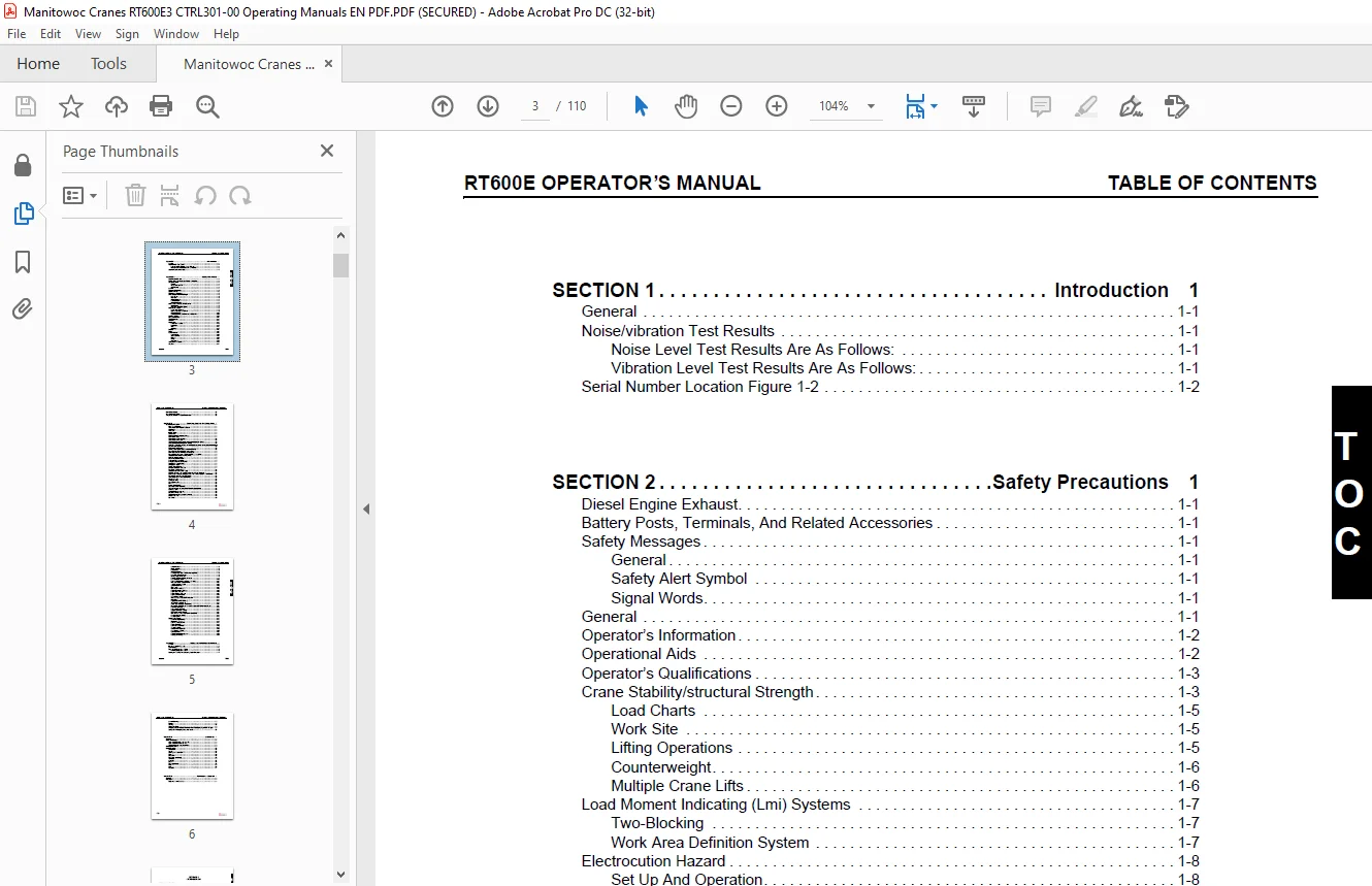
TABLE OF CONTENTS:
Manitowoc Grove Crane RT600E OPERATOR’S MANUAL 301-00 – PDF DOWNLOAD
SECTION 1 Introduction 1
General 1-1
Noise/vibration Test Results 1-1
Noise Level Test Results Are As Follows: 1-1
Vibration Level Test Results Are As Follows: 1-1
Serial Number Location Figure 1-2 1-2
SECTION 2 Safety Precautions 1
Diesel Engine Exhaust 1-1
Battery Posts, Terminals, And Related Accessories 1-1
Safety Messages 1-1
General 1-1
Safety Alert Symbol 1-1
Signal Words 1-1
General 1-1
Operator’s Information 1-2
Operational Aids 1-2
Operator’s Qualifications 1-3
Crane Stability/structural Strength 1-3
Load Charts 1-5
Work Site 1-5
Lifting Operations 1-5
Counterweight 1-6
Multiple Crane Lifts 1-6
Load Moment Indicating (Lmi) Systems 1-7
Two-Blocking 1-7
Work Area Definition System 1-7
Electrocution Hazard 1-8
Set Up And Operation 1-8
Electrocution Hazard Devices 1-9
Electrical Contact 1-10
Special Operating Conditions And Equipment 1-10
Crushing Hazards 1-10
Personnel Handling 1-11
Travel Operation 1-12
Accidents 1-12
Maintenance 1-12
Service And Repairs 1-13
Lubrication 1-13
Tires 1-13
Wire Rope 1-13
Batteries 1-14
Engine 1-15
Work Practices 1-15
Crane Access 1-15
Job Preparation 1-15
Working 1-15
Lifting 1-16
Hand Signals 1-16
Transporting The Crane 1-17
Shut-down 1-17
TABLE OF CONTENTS RT600E OPERATOR’S MANUAL
TOC-2
Boom Extension/jib 1-18
Cold Weather Operation 1-18
Temperature Effects On Hydraulic Cylinders 1-18
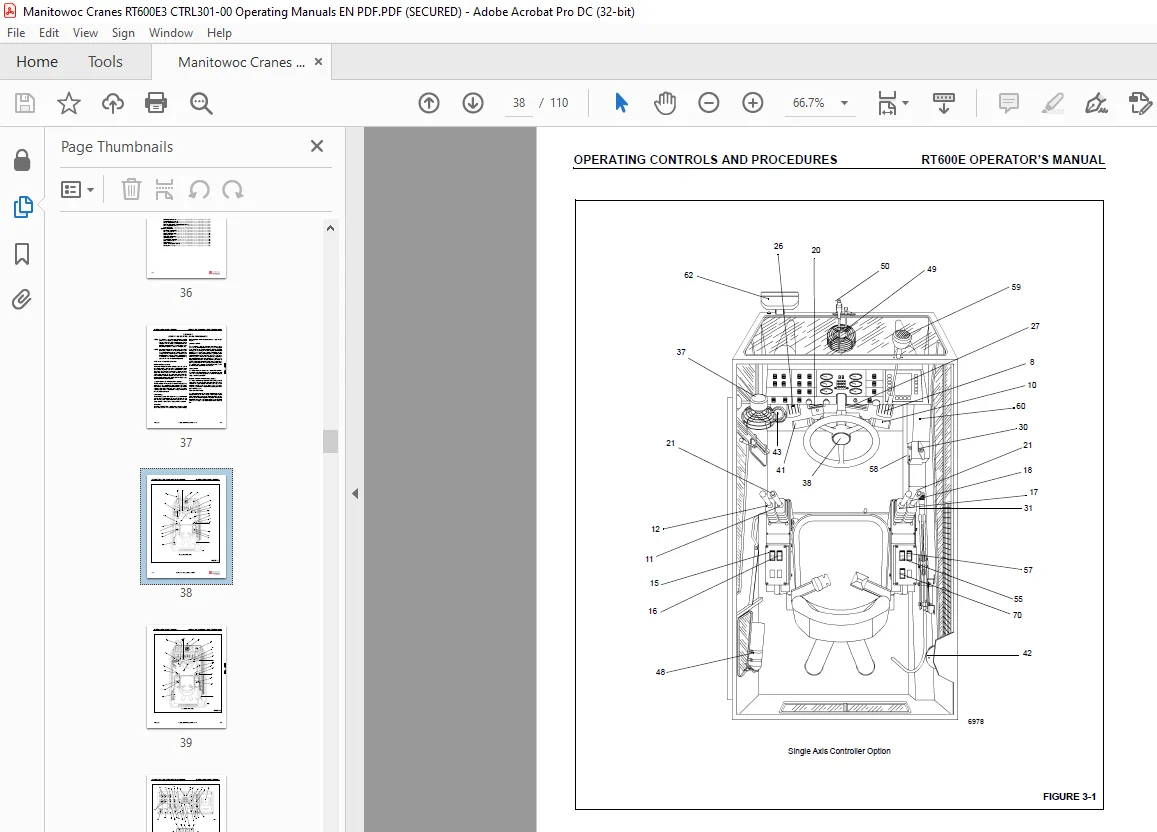
SECTION 2 Operating Controls And Procedures 1
Controls And Indicators 1-1
Hand Throttle Control 1-1
Transmission Oil Temperature Gauge 1-1
Fuel Gauge 1-1
Voltmeter 1-1
Ignition Switch 1-1
Tachometer 1-1
Engine Coolant Temperature Gauge 1-1
Foot Throttle Pedal 1-1
Crane Function Power Switch 1-6
Transmission Shift Lever 1-6
Telescope or Auxiliary Hoist Control Lever (Single Axis Option) 1-6
Swing Control Lever (Single Axis Option) 1-6
Swing And Telescope or Swing and Auxiliary Hoist Control Lever (Dual Axis Option)1-6
Water In Fuel Indicator 1-6
Rear Steer Control Switch 1-6
Auxiliary Hoist Speed Selector Switch (Optional) 1-6
Boom Lift Control Lever (Single Axis Option) 1-7
Main Hoist Control Lever (Single Axis Option) 1-7
Boom Lift And Main Hoist Control Lever (Dual Axis Option) 1-7
Telescope Control Foot Pedal (Optional) 1-7
Hoist Rotation Indicators 1-7
Drive Axle Selector Switch 1-7
Outrigger Control Switches 1-7
Outriggers Extend/Retract Switch 1-7
Swing Brake Control Switch 1-7
Swing Brake Pedal 1-7
Service Brake Foot Pedal 1-7
Low Brake Pressure Indicator 1-7
Park Brake Control Switch 1-8
Turntable Lock Control (Pin Type) 1-8
360 Degree Swing Lock Control (Positive Lock Type) (Optional) 1-8
Load Moment Indicating (LMI) and Work Area Definition System Control Panel 1-8
Low Steer Pressure Indicator (CE Units) 1-8
Transmission Service Indicator (XMSN) 1-8
Headlights Switch 1-8
Work Light Switch 1-8
Cab Circulating Fan 1-8
Horn 1-8
Hazard Lights Switch 1-8
Boom Light Switch (Optional) 1-8
Turn Signal Lever and Windshield Wiper/Washer Controls 1-8
Cab Dome Light 1-9
Skylight Wiper (Not Shown) 1-9
Bubble Level Indicator 1-9
Air Conditioner Control Switch (Optional) 1-9
Heat Control Knob 1-9
Fan Switch 1-9
TOC-3
RT600E OPERATOR’S MANUAL TABLE OF CONTENTS
T
OC
GROVE
Defroster Switch 1-9
Fire Extinguisher 1-9
Defroster Fan 1-9
Windshield Wiper 1-9
Axle Differential Lock Control Switch (Optional) 1-9
Right Turn Signal Indicator 1-9
Left Turn Signal Indicator 1-9
Rear Wheels Not Centered Indicator 1-9
Hydraulic Boost Switch 1-10
Hoist 3rd Wrap Indicator (Optional CE Units) 1-10
Main Hoist Speed Selector Switch 1-10
12 VDC Accessory Outlet 1-10
Spotlight (Optional) 1-10
Fuse Panel 1-10
Wait To Start Indicator 1-10
Engine Diagnostics Switches 1-10
Engine Stop Indicator 1-10
Engine Warning Indicator 1-10
Engine Service Indicator 1-10
Throttle Mode Switch 1-11
Electronic System Diagnostic Indicator 1-11
Work Light 1-11
Boom Glide Switch (Optional) 1-11
-29oC Indicator (Optional) 1-11
Strobe Light or Beacon (Not Shown) 1-11
LMI Lockout (All Units) and LMI Lockout Alarm (CE Units) (Not Shown) 1-11
Buzzer (Not Shown) 1-11
Hourmeter (Not Shown) 1-11
Skylight Wiper (Not Shown) 1-11
Backup Alarm (Not Shown) 1-11
Data Link and Service Connector (Not Shown) 1-11
Anemometer (Not Shown) 1-11
Emergency Exit 1-11
Operating Procedures 1-12
New Crane Conditioning 1-12
Pre-Starting Checks 1-12
Cold Weather Operation 1-13
Engine Operation 1-13
Crane Travel Operation 1-15
Travel On Slopes 1-17
General Crane Operation 1-19
Using Your Load Chart 1-19
Crane Functions 1-21
Control Lever Lockout System 1-26
Stowing And Parking 1-26
SECTION 4 Set-up And Installation Procedures 1
General 1-1
Installing Cable On The Hoist 1-1
Cable Reeving 1-1
Dead-end Rigging/wedge Sockets 1-5
Installing Wedge And Socket 1-5
Erecting And Stowing The Swingaway Boom Extension 1-7
TABLE OF CONTENTS RT600E OPERATOR’S MANUAL
TOC-4
General Warnings 1-7
Erecting 1-7
Stowing 1-8
Setting The Offset 1-12
Changing Swingaway Boom Extension From Telescoping Type To Fixed Type 1-12
Setting The Telescoping Swingaway Length 1-13
SECTION 5 Lubrication 1
General 1-1
Lubrication Intervals 1-1
Arctic Conditions Below -18°C (0°F) 1-1
Arctic Conditions Down To -40°F 1-1
Surface Protection for Cylinder Rods 1-2
Wire Rope Lubrication 1-2
lubrication points 1-3
CraneLUBE 1-3
Safety 1-3
Steering and Suspension 1-4
Axles 1-6
Drive Train 1-8
Drive Train (continued) 1-10
Turntable 1-12
Outriggers 1-14
Boom 1-16
Boom (continued) 1-18
Hoist 1-20
Hoist 1-22
Hydraulic 1-24
SECTION 5 Maintenance Checklist 1
General 1-1
Instructions 1-1
Daily or 10 Hour Check List 1-1
TABLE OF CONTENTS
General 1-1
Noise/vibration Test Results 1-1
Noise Level Test Results Are As Follows: 1-1
Vibration Level Test Results Are As Follows: 1-1
Serial Number Location Figure 1-1 1-2
Need help? Contact: [email protected]
S.M