Manitowoc Grove Crane TM9120 Operator’s & Safety Handbook Manual PDF
$26.95
The Manitowoc Grove Crane TM9120 Superstructure Operator’s & Safety Handbook is a critical resource in PDF format. Download for comprehensive guidance on TM9120 model operation, focusing on safety protocols and efficient usage.
Description
Manitowoc Grove Crane TM9120 SUPERSTRUCTURE Operator’s & Safety Handbook Manual – PDF DOWNLOAD
FILE DETAILS:
Manitowoc Grove Crane TM9120 SUPERSTRUCTURE Operator’s & Safety Handbook Manual – PDF DOWNLOAD
Language : English
Pages :186
Downloadable : Yes
File Type : PDF
IMAGES PREVIEW OF THE MANUAL:
TABLE OF CONTENTS:
Manitowoc Grove Crane TM9120 SUPERSTRUCTURE Operator’s & Safety Handbook Manual – PDF DOWNLOAD
TABLE OF CONTENTS
Page
Section 1 – INTRODUCTION 1-1
Section 2 – SAFETY PRECAUTIONS 2-1
GENERAL 2-1
OPERATOR’S INFORMATION 2-2
OPERATOR’S QUALIFICATION 2-3
CRANE STABILITY/STRUCTURAL STRENGTH 2-4
Load Charts 2-6
Work Site 2-6
Lifting Operations 2-7
Counterweight 2-9
Multiple Crane Lifts 2-9
TWO-BLOCKING 2-1 o
LOAD MOMENT INDICATING SYSTEMS 2-11
ELECTROCUTION HAZARD 2-12
Set-Up and Operation 2-13
Electrocution Hazard Devices 2-14
Electrical Contact 2-16
Special Operating Conditions and Equipment 2-16
CRUSHING HAZARDS 2-17
PERSONNEL HANDLING 2-18
MAINTENANCE 2-19
Service and Repairs 2-20
Lubrication 2-20
Tires 2-21
Wire Rope 2-21
BATTERIES 2-23
ENGINE 2-24
WORK PRACTICES 2-24
Crane Access 2-24
Job Preparation 2-25
Working 2-25
Lifting 2-27
Hand Sign·1ls 2-28
TRAVELING 2-29
SHUT-DOWN 2-30
BOOM EXTENS :ON/JIB 2-31
COLD WEATHEn OPERATION 2-33
Section 3 – CAB CONTROLS AND INDICATORS 3-1
ENGINE CONTROLS AND INDICATORS 3-1
Engine Oil Pressure Gauge 3-1
Fuel Gauge 3-1
Cold Start Switch 3-8
Voltmeter 3-8
Ignition Switch 3-8
Ignition On Indicator 3-8
Hand Throttle Lock Control 3-8
Tachometer/Hourmeter 3-9
Engine Temperature Gauge 3-9
Engine Distress Indicator 3-9
Foot Throttle Pedal 3-9
CRANE CONTROLS AND INDICATORS 3-9
Swing and Telescope or Auxiliary Hoist Control Lever
(Dual Axis Controller) 3-9
Telescope or Auxiliary Hoist Control Lever
(Single Axis Controller) 3-1 O
Swing Control Lever (Single Axis Controller) 3-1 O
Swing Horn Button 3-1 O
Boom Lift and Main Hoist Control Lever
(Dual Axis Controller) 3-1 O
Boom Lift Control Lever (Single Axis Controller) 3-1 O
Main Hoist Control Lever (Single Axis Controller) 3-1 O
Telescope Control Pedal 3-11
Lift/felescope Boost Control Switch 3-11
Fly Lock Pin Switch 3-11
Fly Lock Pin Circuit Breaker 3-11
Fly Pin Engaged Indicator 3-11
Fly Pin Disengaged Indicator 3-11
Fly Pin Distress Indicator 3-11
Auxiliary Hoist Switch 3-11
Hoist Boost Control Switch 3-12
Hoist Boost Indicator Light 3-12
Hoist Rotation Indicators 3-12
Third Wrap Indicator Light 3-12
Crane Function Power Switch 3-12
Outrigger Selector Panel 3-12
Outrigger Extension/Retraction Switch 3-13
Center Front Stabilizer Control Switch 3-13
Front Stabilizer Overloaded Indicator 3-13
Bubble Level Indicator 3-13
ix
Swing Brake Control Switch 3-13
Swing Brake Pedal 3-14
Swing Brake On Indicator 3-14
Swing Lock Control (Pin Type) 3-14
Swing Lock Control (Positive Lock Type) 3-14
ACCESSORY CONTROLS AND INDICATORS 3-14
Panel Light Control 3-14
Work Light Switch 3-14
Boom Flood Lights Switch 3-15
Armrest Adjustment Lever 3-15
Cab Circulating Fan 3-15
Cab Dome Light 3-15
Fire Extinguisher 3-15
Windshield Wiper Switch 3-15
Heater Control Switch 3-16
Heat Control 3-16
Section 4 – OPERA TING PROCEDURES 4-1
PRE-STARTING CHECKS 4-1
Fuel Supply 4-1
Engine Oil 4-1
Engine Coolant 4-1
Batteries 4-1
Daily Lubrication • 4-1
Hydraulic Reservoir and Filter 4-1
Wire Rope 4-2
Hook Block 4-2
Swingaway Extension 4-2
Air Cleaner 4-2
COLD WEATHER OPERATION 4-3
ENGINE OPERATION 4-3
Starting Procedure 4-3
Cold Weather Starting 4-4
Idling the Engine 4-5
Racing the Engine 4-5
Shutdown Procedure 4-5
Control Lever Operation 4-6
Preload Check 4-6
USING YOUR LOAD CHART 4-7
X
TABLE OF CONTENTS (continued}
Page
CRANE FUNCTIONS 4-9
Setting the Outriggers 4-9
Stowing the Outriggers 4-11
Setting the Center Front Stabilizer 4-12
Stowing the Center Front Stabilizer 4-12
Swinging the Boom 4-13
Elevating and Lowering the Boom 4-14
Elevating the Boom 4-14
Lowering the Boom 4-15
Emergency Boom Operating Procedures 4-15
Telescoping the Boom 4-16
Extending the Boom 4-16
Retracting the Boom 4-16
Pinning the Boom Fly Section 4-17
Pinning 4-17
Unpinning the Fly Section 4-17
Lowering and Raising the Cable 4-18
Lowering the Cable 4-1 8
Raising the Cable 4-1 8
Stowing and Parking 4-19
Recommended Crane Shutdown Procedures 4-19
OPTIONAL EQUIPMENT OPERATION 4-20
Diesel Fuel Heater 4-20
Starting 4-20
Operating 4-20
Stopping 4-21
Cold Weather Fuel Requirements 4-21
Propane Heater 4-21
Starting 4-21
Operating 4-22
Stopping 4-22
OPERATIONAL AIDS 4-22
General 4-22
Load Moment Indicating System 4-22
Antitwo-block System 4-23
Control Lever Lockout System 4-23
Section 5 – LUBRICATION 5-1
GENERAL • 5-1
LUBRICATION POINTS 5-1
WIRE ROPE LUBRICATION 5-14
xi
TABI E OF CONTENTS (continued}
Page
Section 6 -SET UP AND INSTALLATION PROCEDURES 6-1
GENERAL 6-1
INSTALLING CABLE ON THE HOIST 6-1
CABLE REEVING 6-2
DEAD-END RIGGING/WEDGE SOCKETS 6-2
Installing the Wedge and Socket 6-4
ERECTING AND STOWING THE SWINGAWAY
BOOM EXTENSION 6-6
Erecting 6-6
Stowing 6-15
Setting the Offset 6-16
Setting the Telescoping Extension Length 6-18
Extending 6-18
Retracting 6-19
ERECTING AND STOWING THE MUL Tl-SECTION
LATTICE JIB FROM THE GROUND 6-20
Erecting the 74-Foot (22 5 M) Jib 6-21
Erecting the 88-Foot (26 8 M) Jib 6-31
Erecting the 102-Foot (31 0 M) Jib 6-31
Erecting the 116-Foot (35 3 M) Jib 6-31
Jib Removal 6-32
ERECTING AND STOWING THE MUL Tl-SECTION
LATTICE JIB FROM A TRAILER 6-33
Jib Erection 6-35
Jib Removal 6-37
JOBSITE TRAVEL WITH LATTICE JIB 6-39
REMOVABLE COUNTERWEIGHT 6-45
When Using Upper and Lower Counterweights 6-46
Removal 6-46
Installation 6-46
When Using Upper Counterweight Only 6-47
Removal 6-47
Installation 6-50
When Removing Lower Counterweight Only 6-51
Removal 6-51
Installation 6-52
xii
TABLE OF CONTENTS (continued}
Page
FRONT AND REAR OUTRIGGER BOX REMOVAL 6-53
Front Outrigger Box Removal 6-54
Rear Outrigger Box Removal 6-60
FRONT AND REAR OUTRIGGER BOX INSTALLATION 6-64
Rear Outrigger Box Installation 6-64
Front Outrigger Box Installation 6-65
TRAILING BOOM CARRIER 6-67
Preparation for Highway Transport 6-67
Installation and Removal of the Trailing Boom Carrier 6-68
Trailing Boom Operation 6-74
Returning to Normal Crane Operation 6-75
Travel Precautions 6-76
Parking the Boom Trailer/Dolly 6-76
LIST OF FIGURES
Title Page
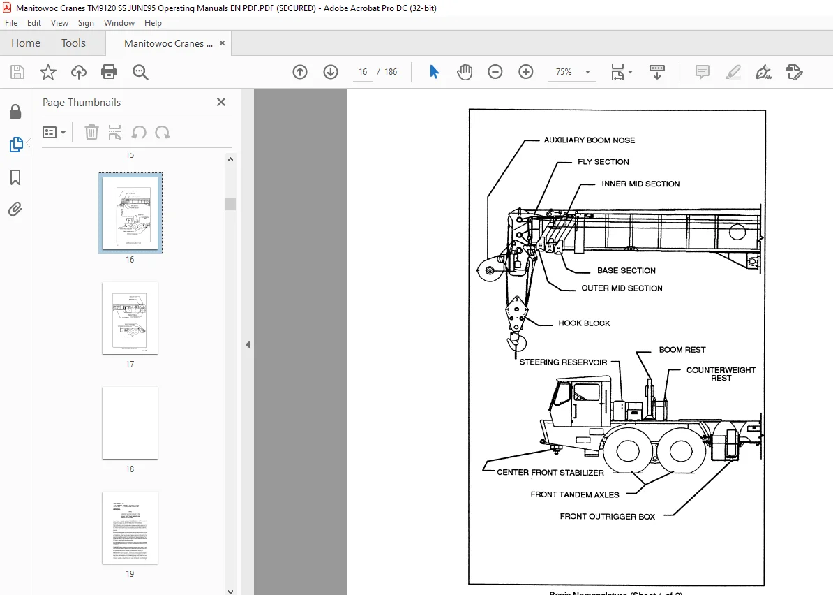
Basic Nomenclature 1-2
Cab Controls and Indicators 3-2
Terms to Know 4-7
Lubrication Chart 5-4
Installing Cable Anchor Wedge 6-2
Dead-End Rigging/Wedge Socket 6-5
Erecting and Stowing the Swingaway Boom Extension 6-8
Offset Positions 6-17
Multi-Section Lattice Jib Erection 6-22
Upper and Lower Counterweight Demounted 6-45
Upper Counterweight Resting on Stand 6-47
Counterweight Removal System 6-48
Lower Counterweight Demounted 6-52
Front Outrigger Box Removal 6-57
Rear Outrigger Box Removal 6-62
Loading Hook Block With Auxiliary Lifting Device Available 6-69
Trailing Boom Carrier 6-70
Self Loading Hook Block 6-73
Wire Rope Clip Torque Values 6-5
Permissible Jobsite Travel Chart with Boom Over Front of Carrier
with 7 4-116′ Jib Installed 6-40
Permissible Jobsite Travel Chart with Boom Over Rear of Carrier
with 7 4-116′ Jib Installed 6-42
Questions? Email us: [email protected]
S.M