Manitowoc National Crane 400B Operator & Service Manual – PDF DOWNLOAD
$29.95
The Manitowoc National Crane 400B Operator & Service Manual in PDF is essential for safe operation and maintenance. Download for detailed instructions and reference.
Description
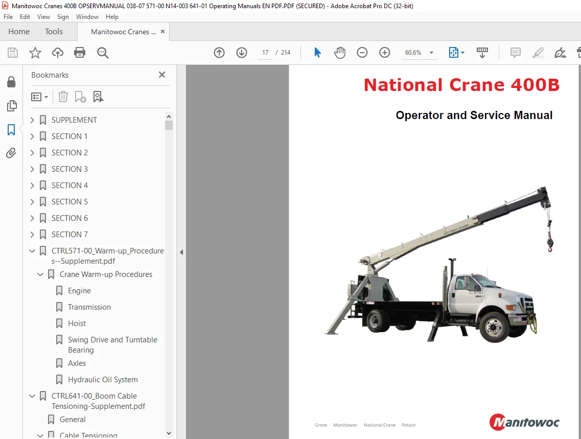
Manitowoc National Crane 400B Operator & Service Manual – PDF DOWNLOAD
FILE DETAILS:
Manitowoc National Crane 400B Operator & Service Manual – PDF DOWNLOAD
Language : English
Pages : 214
Downloadable : Yes
File Type : PDF
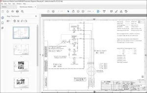
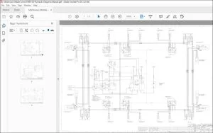
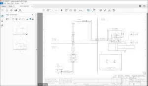
IMAGES PREVIEW OF THE MANUAL:
TABLE OF CONTENTS:
Manitowoc National Crane 400B Operator & Service Manual – PDF DOWNLOAD
SUPPLEMENT 21
Introduction 23
General 23
Supplemental Information 23
Safety Information 23
New Owner 24
General Maintenance 25
Cleanliness 25
Removal and Installation 25
Disassembly And Assembly 25
Pressing Parts 25
Locks 25
Shims 25
Bearings 26
Antifriction Bearings 26
Double Row, Tapered Roller 26
Heating Bearings 26
Installation 26
Preload 26
Sleeve Bearings 26
Gaskets 26
Hydraulic Systems 26
Visual Inspection 26
Valves and Manifolds 26
Hoses and Fittings 26
Cleanliness 26
Keep The System Clean 27
Sealing Elements 27
Hydraulic Lines 27
Electrical 27
Batteries 27
Connectors, Harnesses, Wires, and Connectors 27
Climate Zone Classification 27
Fatigue Of Welded Structures 28
Loctite 28
Application of Medium Strength Loctite 28
Primer Application 28
Adhesive/Sealant Application 28
Fasteners And Torque Values 28
Torque Wrenches 29
Torque Values 29
Weld Studs 32
Wire Rope 33
General 33
Environmental Conditions 33
Dynamic Shock Loads 33
Lubrication 33
Recommendations for Servicing Wire Rope 34
Wire Rope Inspection 34
Daily Inspection 34
Yearly Inspection 34
Boom Extension and Retraction Cables 34
Periodic Inspection 34
Wire Rope Replacement (All Wire Rope) 35
Seizing Wire Rope 35
Method 1 35
Method 2 35
Set-Up 36
Outrigger Setup 36
Proper Leveling of the Crane 36
Bubble Level Adjustment 36
Site Selection 36
Setting the Outriggers 37
Installing Cable on the Hoist 37
Wedge Sockets 38
Terminator Wedge Installation 38
Wedge Socket Installation 39
Outrigger Monitoring System (OMS) (Optional—Standard in North America) 40
Operation 40
400B 40
400B HO with Rear Stabilizer Hydraulic (RSH) 41
400B HO with Angled Stabilizer Hydraulic (ASH) 41
Maintenance 43
Outrigger Cylinder Length Sensor — 400B 43
Remove 43
Install 43
Calibrate 43
Outrigger Proximity Switch — 400B HO 43
Version 1 43
Remove 43
Install 43
Version 2 44
Remove 44
Install 44
Stabilizer Proximity Switch — 400B and 400B HO with Angled Stabilizer Hydraulic (ASH) 44
Version 1 44
Remove 44
Install 44
Version 2 44
Remove 44
Install 44
Side Folding Swing-Around Jib Operation 44
SECTION 1 51
Safety Information 51
Safety Messages 51
General 51
Safety Alert Symbol 51
Signal Words 51
General 51
Accidents 51
Operator’s Information 52
Operator’s Qualifications 52
Operational Aids 53
Rated Capacity Limiter (RCL) Systems (If Equipped) 53
Anti-Two-Blocking Device 54
Work Area Definition System (WADS) (If Equipped) 54
Crane Stability/Structural Strength 55
Load Charts 56
Work Site 56
Wind Forces 56
Lifting Operations 57
Counterweight 58
Outrigger Lift Off 58
Multiple Crane Lifts 58
Electrocution Hazard 58
Set-Up and Operation 59
Electrocution Hazard Devices 60
Electrical Contact 61
Special Operating Conditions and Equipment 61
Personnel Handling 61
Environmental Protection 62
Maintenance 62
Service and Repairs 63
Lubrication 63
Tires 64
Wire Rope 64
Sheaves 65
Batteries 66
Engine 66
Transporting the Crane 66
Travel Operation 66
Work Practices 67
Personal Considerations 67
Crane Access 67
Job Preparation 68
Working 68
Lifting 69
Hand Signals 70
Boom Extension 72
Parking and Securing 72
Shut-Down 72
Cold Weather Operation 72
Temperature Effects on Hook Blocks 73
Temperature Effects on Hydraulic Cylinders 73
Overload Inspection 75
Boom Inspection 76
Superstructure Inspection 78
Carrier Inspection 80
SECTION 2 83
Operation 83
Controls 83
Truck cab controls 83
Crane Power 83
Power Take-Off 83
Park Brake 83
Cold Weather Operation 83
Operation Below -40°C 83
Operation Below -40°F 83
Crane Controls 83
Control Functions 83
Operating Procedures 86
Equipment Familiarization 86
Equipment Checks 86
Pre-Operation Inspection and Calibration Verification 86
Work Site Position 87
Before Leaving The Cab 87
Crane Set Up 87
Before Making The Lift 88
Reading And Understanding The Load Charts 88
General 89
Set-Up 89
Operation 89
Definitions 90
Hoist System Operation 94
Using Multiple Part Lines 94
General Rules When Operating Hoist 94
Lifting The Load 94
Shutting Down And Preparing For Road Travel 95
Optional Hoist Burst Of Speed Operation 95
Anti-two Block System 96
Description/operation 96
Hydraulic Capacity Alert System 97
System Description 97
System Operation 98
Jib Load Limiting Device 99
System Description 99
System Operation 99
Jib Safety And Operation 101
Safety Tips For Jib Operation 102
Side Folding-swing Around Jib Operation 102
Deployment Procedure 102
Stowing Procedure 103
Jib Maintenance 104
Jib Removal 104
SECTION 3 107
Maintenance 107
Inspection and maintenance 107
Inspection 107
Daily inspections 107
Weekly inspections 107
Monthly inspections 108
Periodic inspection 108
Other 108
Wire rope inspection and maintenance 109
Inspection 109
Rope replacement 109
Care of wire rope 110
Rope Construction 110
Crane Loadline (Standard Planetary Hoist) 110
Crane Loadline (Optional High-Pull Hoist) 110
Adjustments and Repairs 111
Tire Load and Inflation Table 112
SECTION 4 115
Lubrication 115
Lubrication procedures and charts 115
Lubricants 115
Hydraulic oil 115
Lubrication points 116
Wire rope lubrication 116
Lubrication chart 117
Hydraulic oil reservoir level 119
Carwell© Rust Inhibitor 119
Protecting Cranes From Corrosion 119
Cleaning Procedures 120
Inspection and Repair 120
Application 120
Areas of Application 121
SECTION 5 125
Service 125
Service and repair 125
Cleanliness 125
Hydraulic systems 125
Fasteners and torque values 125
Label parts when disassembling 126
Welding precautions 126
National crane fitting o-ring part numbers 126
Using Torque Wrench Extensions 127
hoist oil level 128
Rotation gearbox oil level 128
Brake oil level 129
Trouble Diagnosis 130
Anti-two-block internal wire system 135
Operation 135
Maintenance 135
Anti-two block trouble diagnosis – electrical 137
Anti-two block trouble diagnosis – hydraulic 139
Anti-two block trouble diagnosis – hydraulic (continued) 140
Cylinder Disassembly and Repair 141
Extend Cylinder 142
Extend Cylinder Disassembly 142
Extend Cylinder Assembly 142
Three Section Boom Operation 143
Boom Illustrations 144
Boom extended 144
Boom Retracted 144
Three Section Boom Maintenance 145
Internal Cable Sheave Lubrication 145
Three Section Cable Tensioning 145
Three Section Boom Service 146
Boom Removal 146
Boom Disassembly 146
Boom Disassembly Alternative #1 146
Boom Disassembly Alternative #2 147
Additional Maintenance, Disassembled Boom 148
Three Section Boom Assembly 150
Three Section Top/Bottom Pad Replacement Assembled Boom 152
Top Rear Pad Replacement 152
Front Bottom Pad Replacement 152
Inner Wear Pad Calibration 152
Inner Side Pads 153
Inner Boom Pad Lubrication 155
Jib Installation And Adjustment 156
(Optional) Oil Cooler Service & Maintenance 159
Disassembly & Assembly Instructions For Rotation Gearbox 159
Brake Section 159
Trouble Shooting 159
Brake will not release: 159
Brake Disassembly 159
Brake Reassembly 160
Gear Housing Disassembly 160
Gear Housing Reassembly 161
Rotation Gearbox 162
Rotation Stop-mechanical 163
Adjustment Procedure: 163
Method 1 163
Method 2 163
Outrigger Stow Latch Adjustment 164
Servicing The Control Valves 164
Disassembly And Reassembly Of Control Valves To Replace Seals 164
Replacing Spool Seals 164
Unloader Dump Valve – Air Purging Instructions 166
Control Valve Relief Adjustment 166
Hydraulic System Description 166
Hydraulic Capacity Alert System 167
System Adjustment 167
Hydraulic Capacity Alert System Trouble Diagnosis 168
Maintenance & Repair 171
Jib load limiting device 172
System installation 172
Troubleshooting 172
Single character display 173
Electrical schematic 174
Specifications 177
Hydraulic System 177
Hoist System 177
Crane Operating speeds 178
SECTION 6 175
Specifications 175
SECTION 7 179
Crane Installation 179
Typical Locations / Serial Number Identification 180
Minimum Truck Requirements 181
Mounting Configurations 181
Configuration 1 – with subbase 182
Configuration 2 – with subbase and SFO 182
Configuration 3 – with subbase and counterweight 183
Configuration 4 – without subbase 183
Configuration 5 – rear mount with heavy duty subbase 184
Configuration 6 – non-standard 152 in a- frame outriggers 184
PTO Horsepower Requirements 185
Direct Mount Pump To PTO 185
Pump Rotation 185
PTO Selection 186
Truck Frame Strength 187
Section Modulus Tables 187
Section Modulus in3 (cm3) 188
Section Modulus in3 (cm3) 189
Section Modulus in3 (cm3) 189
Section Modulus in3 (cm3) 190
EXAMPLE: 190
Truck Frame Requirements For Optional Front Stabilizer 192
Section Modulus Tables 193
Section Modulus in3 (cm3) 193
Section Modulus in3 (cm3) 194
Example: 195
Truck Preparation 196
Welding Precautions 196
Positioning Crane On Truck 196
PTO, Pump, Reservoir 196
Reinforcing After Frame is Extended 197
After Frame Modification 201
Crane Installation 201
Pin Bearing Inspection and Installation Procedure 204
Pin inspection 204
Bearing Inspection 205
Trunnion Inspection 205
Installation 205
Counterweighting 205
Example 206
Counterweighting Methods For Stability Around The Rear 180° 208
Example 210
Initial Crane Run In Procedure 210
Boom Rests 210
Stability Check 212
Optional Cross Frame Outrigger Installation 212
CTRL571-00_Warm-up_Procedures–Supplement pdf 0
Crane Warm-up Procedures 15
Engine 15
Transmission 15
Hoist 15
Swing Drive and Turntable Bearing 15
Axles 16
Hydraulic Oil System 16
CTRL641-00_Boom Cable Tensioning-Supplement pdf 0
General 0
Cable Tensioning 0
Tensioning Setup Procedure 0
1 Mark the front of each section with a chalk line as indicated in Figure 1 0
2 Extend and retract boom several times to establish working state of cables 0
3 Extend boom so scribed lines are exposed by approximately 12 inches 0
4 Measure the extension gaps between each boom section and scribed line and note values 0
5 Retract boom so that the scribed lines are exposed by approximately 6 inches 0
6 Measure the retraction gaps between each boom section and scribed line and note values 0
7 Extend and retract the boom a few times and then repeat measuring the extension gaps 0
8 Adjust all corresponding cables according to Cable Tightening Sequence instructions 0
Figure 1 0
Cable Tension Sequence 0
Five section boom with two stage cylinder 0
1 321 retract cables 0
2 123 extend (synchronizing) cables 0
3 234 extend cables 0
4 432 retract cables 0
5 345 extend cables 0
6 543 retract cables 0
Four section boom with two stage cylinder 0
1 321 retract cables 0
2 123 extend (synchronizing) cables 0
3 234 extend cables 0
4 432 retract cables 0
Four section boom with one stage cylinder 0
1 123 extend cables 0
2 321 retract cables 0
3 234 extend cables 0
4 432 retract cables 0
Three section boom with one stage cylinder 0
1 123 extend cables 0
2 321 retract cables 0
5 – Section Boom w/ 2 Stage Cylinder Cable Positioning 0
Figure 2 0
Cable Tightening Sequence 5 Section Boom with Two Stage Extend Cylinder 0
321 and 123 cable balancing 0
Extension 0
1 Measure the extension gaps between the first and second section and the second and third section 0
2 Tighten 321 retract cable located at the front bottom of the base section the difference in the extension gap measurements 0
3 Extend and retract the boom a few times and then repeat measuring the extension gaps 0
4 Tightening until the extension gap between the first and second section and the extension gap between the second and the third are equal 0
Retraction 0
1 Measure the retraction gaps between the first and second section and the second and third section 0
2 Tighten the 123 synchronizing cable located at the back of the base section the difference in the retraction gap measurements 0
3 Extend and retract the boom a few times and then repeat measuring the retraction gaps 0
4 Tightening until the retraction gap between the first and second section and the retraction gap between the second and the third are equal 0
234 and 432 cable balancing 0
Extension 0
1 Measure the extension gaps between the third and fourth section and the second and third section 0
2 Tighten the 234 extend cable located at the back top of the second section the difference in the extension gap measurements 0
3 Extend and retract the boom a few times and then repeat measuring the extension gaps 0
4 Tightening until the extension gap between the third and fourth section is equal to the extension gap between the second and third section 0
Retraction 0
1 Measure the retraction gaps between the second and third section and the third and fourth section 0
2 Tighten the 432 retract cable located at the front bottom of the second section the difference in the retraction gap measurements 0
3 Extend and retract the boom a few times and then repeat measuring the retraction gaps 0
4 Tightening until the retraction gap between the third and fourth section is equal to the retraction gap between the second and third section 0
345 and 543 cable balancing 0
Extension 0
1 Measure the extension gaps between the fourth and fifth section and the third and fourth section 0
2 Tighten the 345 extend cable located at the back top of the third section the difference in the extension gap measurements 0
3 Extend and retract the boom a few times and then repeat measuring the extension gaps 0
4 Tightening until the extension gap between the fifth and fourth section is equal to the extension gap between the fourth and third section 0
Retraction 0
1 Measure the retraction gaps between the fourth and fifth section and the third and fourth section 0
2 Tighten the 543 retract cable located at the front bottom of the third section the difference in the retraction gap measurements 0
3 Extend and retract the boom a few times and then repeat measuring the retraction gaps 0
4 Tightening until the retraction gap between the fifth and fourth section is equal to the retraction gap between the fourth and third section 0
4- Section Boom w/ 2 Stage Cylinder Cable Positioning 0
Figure 3 0
Cable Tightening Sequence 4 Section Boom with Two Stage Extend Cylinder 0
321 and 123 cable balancing 0
Extension 0
1 Measure the extension gaps between the first and second section and the second and third section 0
2 Tighten 321 retract cable located at the front bottom of the base section the difference in the extension gap measurements 0
3 Extend and retract the boom a few times and then repeat measuring the extension gaps 0
4 Tightening until the extension gap between the first and second section and the extension gap between the second and the third are equal 0
Retraction 0
1 Measure the retraction gaps between the first and second section and the second and third section 0
2 Tighten the 123 synchronizing cable located at the back of the base section the difference in the retraction gap measurements 0
3 Extend and retract the boom a few times and then repeat measuring the retraction gaps 0
4 Tightening until the retraction gap between the first and second section and the retraction gap between the second and the third are equal 0
234 and 432 cable balancing 0
Extension 0
1 Measure the extension gaps between the third and fourth section and the second and third section 0
2 Tighten the 234 extend cable located at the back top of the second section the difference in the extension gap measurements 0
3 Extend and retract the boom a few times and then repeat measuring the extension gaps 0
4 Tightening until the extension gap between the third and fourth section is equal to the extension gap between the second and third section 0
Retraction 0
1 Measure the retraction gaps between the second and third section and the third and fourth section 0
2 Tighten the 432 retract cable located at the front bottom of the second section the difference in the retraction gap measurements 0
3 Extend and retract the boom a few times and then repeat measuring the retraction gaps 0
4 Tightening until the retraction gap between the third and fourth section is equal to the retraction gap between the second and third section 0
4- Section Boom w/ 1 Stage Cylinder Cable Positioning 0
Figure 4 0
Cable Tightening Sequence 4 Section Boom with (1) Stage Extend Cylinder 0
321 and 123 cable balancing 0
Extension 0
1 Measure the extension gaps between the first and second section and the second and third section 0
2 Tighten 123 extend cable located at the back top of the base section the difference in the extension gap measurements 0
3 Extend and retract the boom a few times and then repeat measuring the extension gaps 0
4 Tightening until the extension gap between the first and second section and the extension gap between the second and the third are equal 0
Retraction 0
1 Measure the retraction gaps between the first and second section and the second and third section 0
2 Tighten the 321 retract cable located at the front bottom of the base section the difference in the retraction gap measurements 0
3 Extend and retract the boom a few times and then repeat measuring the retraction gaps 0
4 Tightening until the retraction gap between the first and second section and the retraction gap between the second and the third are equal 0
234 and 432 cable balancing 0
Extension 0
1 Measure the extension gaps between the third and fourth section and the second and third section 0
2 Tighten the 234 extend cable located at the back top of the second section the difference in the extension gap measurements 0
3 Extend and retract the boom a few times and then repeat measuring the extension gaps 0
4 Tightening until the extension gap between the third and fourth section is equal to the extension gap between the second and third section 0
Retraction 0
1 Measure the retraction gaps between the second and third section and the third and fourth section 0
2 Tighten the 432 retract cable located at the front bottom of the second section the difference in the retraction gap measurements 0
3 Extend and retract the boom a few times and then repeat measuring the retraction gaps 0
4 Tightening until the retraction gap between the third and fourth section is equal to the retraction gap between the second and third section 0
3- Section Boom w/ 1 Stage Cylinder Cable Positioning 0
Figure 5 0
Cable Tightening Sequence 3 Section Boom with (1) Stage Extend Cylinder 0
321 and 123 cable balancing 0
Extension 0
1 Measure the extension gaps between the first and second section and the second and third section 0
2 Tighten 123 extend cable located at the back top of the base section the difference in the extension gap measurements 0
3 Extend and retract the boom a few times and then repeat measuring the extension gaps 0
4 Tightening until the extension gap between the first and second section and the extension gap between the second and the third are equal 0
Retraction 0
1 Measure the retraction gaps between the first and second section and the second and third section 0
2 Tighten the 321 retract cable located at the front bottom of the base section the difference in the retraction gap measurements 0
3 Extend and retract the boom a few times and then repeat measuring the retraction gaps 0
4 Tightening until the retraction gap between the first and second section and the retraction gap between the second and the third are equal 0
Figure 6 0
Cable Retention 0
TORQUE VALUES for Second Nut: 0
CTRL641-01_Boom Cable Tensioning-Supplement pdf 0
General 3
Cable Tensioning 3
Tensioning Setup Procedure 3
1 Mark the front of each section with a chalk line as indicated in Figure 1 3
2 Extend and retract boom several times to establish working state of cables 3
3 Extend boom so scribed lines are exposed by approximately 12 inches 3
4 Measure the extension gaps between each boom section and scribed line and note values 3
5 Retract boom so that the scribed lines are exposed by approximately 6 inches 3
6 Measure the retraction gaps between each boom section and scribed line and note values 3
7 Extend and retract the boom a few times and then repeat measuring the extension gaps 3
8 Adjust all corresponding cables according to Cable Tightening Sequence instructions 3
Figure 1 3
Cable Tension Sequence 3
Five section boom with two stage cylinder 3
1 321 retract cables 3
2 123 extend (synchronizing) cables 3
3 234 extend cables 3
4 432 retract cables 3
5 345 extend cables 3
6 543 retract cables 4
Four section boom with two stage cylinder 4
1 321 retract cables 4
2 123 extend (synchronizing) cables 4
3 234 extend cables 4
4 432 retract cables 4
Four section boom with one stage cylinder 4
1 123 extend cables 4
2 321 retract cables 4
3 234 extend cables 4
4 432 retract cables 4
Three section boom with one stage cylinder 4
1 123 extend cables 4
2 321 retract cables 4
5 – Section Boom w/ 2 Stage Cylinder Cable Positioning 4
Figure 2 4
Cable Tightening Sequence 5 Section Boom with Two Stage Extend Cylinder 4
321 and 123 cable balancing 4
Extension 4
1 Measure the extension gaps between the first and second section and the second and third section 4
2 Tighten 321 retract cable located at the front bottom of the base section the difference in the extension gap measurements 4
3 Extend and retract the boom a few times and then repeat measuring the extension gaps 4
4 Tightening until the extension gap between the first and second section and the extension gap between the second and the third are equal 4
Retraction 4
1 Measure the retraction gaps between the first and second section and the second and third section 4
2 Tighten the 123 synchronizing cable located at the back of the base section the difference in the retraction gap measurements 4
3 Extend and retract the boom a few times and then repeat measuring the retraction gaps 4
4 Tightening until the retraction gap between the first and second section and the retraction gap between the second and the third are equal 5
234 and 432 cable balancing 5
Extension 5
1 Measure the extension gaps between the third and fourth section and the second and third section 5
2 Tighten the 234 extend cable located at the back top of the second section the difference in the extension gap measurements 5
3 Extend and retract the boom a few times and then repeat measuring the extension gaps 5
4 Tightening until the extension gap between the third and fourth section is equal to the extension gap between the second and third section 5
Retraction 5
1 Measure the retraction gaps between the second and third section and the third and fourth section 5
2 Tighten the 432 retract cable located at the front bottom of the second section the difference in the retraction gap measurements 5
3 Extend and retract the boom a few times and then repeat measuring the retraction gaps 5
4 Tightening until the retraction gap between the third and fourth section is equal to the retraction gap between the second and third section 5
345 and 543 cable balancing 5
Extension 5
1 Measure the extension gaps between the fourth and fifth section and the third and fourth section 5
2 Tighten the 345 extend cable located at the back top of the third section the difference in the extension gap measurements 5
3 Extend and retract the boom a few times and then repeat measuring the extension gaps 5
4 Tightening until the extension gap between the fifth and fourth section is equal to the extension gap between the fourth and third section 5
Retraction 5
1 Measure the retraction gaps between the fourth and fifth section and the third and fourth section 5
2 Tighten the 543 retract cable located at the front bottom of the third section the difference in the retraction gap measurements 5
3 Extend and retract the boom a few times and then repeat measuring the retraction gaps 5
4 Tightening until the retraction gap between the fifth and fourth section is equal to the retraction gap between the fourth and third section 5
4- Section Boom w/ 2 Stage Cylinder Cable Positioning 6
Figure 3 6
Cable Tightening Sequence 4 Section Boom with Two Stage Extend Cylinder 6
321 and 123 cable balancing 6
Extension 6
1 Measure the extension gaps between the first and second section and the second and third section 6
2 Tighten 321 retract cable located at the front bottom of the base section the difference in the extension gap measurements 6
3 Extend and retract the boom a few times and then repeat measuring the extension gaps 6
4 Tightening until the extension gap between the first and second section and the extension gap between the second and the third are equal 6
Retraction 6
1 Measure the retraction gaps between the first and second section and the second and third section 6
2 Tighten the 123 synchronizing cable located at the back of the base section the difference in the retraction gap measurements 6
3 Extend and retract the boom a few times and then repeat measuring the retraction gaps 6
4 Tightening until the retraction gap between the first and second section and the retraction gap between the second and the third are equal 6
234 and 432 cable balancing 6
Extension 6
1 Measure the extension gaps between the third and fourth section and the second and third section 6
2 Tighten the 234 extend cable located at the back top of the second section the difference in the extension gap measurements 6
3 Extend and retract the boom a few times and then repeat measuring the extension gaps 6
4 Tightening until the extension gap between the third and fourth section is equal to the extension gap between the second and third section 7
Retraction 7
1 Measure the retraction gaps between the second and third section and the third and fourth section 7
2 Tighten the 432 retract cable located at the front bottom of the second section the difference in the retraction gap measurements 7
3 Extend and retract the boom a few times and then repeat measuring the retraction gaps 7
4 Tightening until the retraction gap between the third and fourth section is equal to the retraction gap between the second and third section 7
4- Section Boom w/ 1 Stage Cylinder Cable Positioning 7
Figure 4 7
Cable Tightening Sequence 4 Section Boom with (1) Stage Extend Cylinder 7
321 and 123 cable balancing 7
Extension 7
1 Measure the extension gaps between the first and second section and the second and third section 7
2 Tighten 123 extend cable located at the back top of the base section the difference in the extension gap measurements 7
3 Extend and retract the boom a few times and then repeat measuring the extension gaps 7
4 Tightening until the extension gap between the first and second section and the extension gap between the second and the third are equal 7
Retraction 7
1 Measure the retraction gaps between the first and second section and the second and third section 7
2 Tighten the 321 retract cable located at the front bottom of the base section the difference in the retraction gap measurements 7
3 Extend and retract the boom a few times and then repeat measuring the retraction gaps 7
4 Tightening until the retraction gap between the first and second section and the retraction gap between the second and the third are equal 8
234 and 432 cable balancing 8
Extension 8
1 Measure the extension gaps between the third and fourth section and the second and third section 8
2 Tighten the 234 extend cable located at the back top of the second section the difference in the extension gap measurements 8
3 Extend and retract the boom a few times and then repeat measuring the extension gaps 8
4 Tightening until the extension gap between the third and fourth section is equal to the extension gap between the second and third section 8
Retraction 8
1 Measure the retraction gaps between the second and third section and the third and fourth section 8
2 Tighten the 432 retract cable located at the front bottom of the second section the difference in the retraction gap measurements 8
3 Extend and retract the boom a few times and then repeat measuring the retraction gaps 8
4 Tightening until the retraction gap between the third and fourth section is equal to the retraction gap between the second and third section 8
3- Section Boom w/ 1 Stage Cylinder Cable Positioning 8
Figure 5 8
Cable Tightening Sequence 3 Section Boom with (1) Stage Extend Cylinder 8
321 and 123 cable balancing 8
Extension 8
1 Measure the extension gaps between the first and second section and the second and third section 8
2 Tighten 123 extend cable located at the back top of the base section the difference in the extension gap measurements 8
3 Extend and retract the boom a few times and then repeat measuring the extension gaps 9
4 Tightening until the extension gap between the first and second section and the extension gap between the second and the third are equal 9
Retraction 9
1 Measure the retraction gaps between the first and second section and the second and third section 9
2 Tighten the 321 retract cable located at the front bottom of the base section the difference in the retraction gap measurements 9
3 Extend and retract the boom a few times and then repeat measuring the retraction gaps 9
4 Tightening until the retraction gap between the first and second section and the retraction gap between the second and the third are equal 9
Figure 6 9
Cable Retention 9
TORQUE VALUES for Second Nut: 10
Customer Support: [email protected]
S.V