Manitowoc National Crane NBT15 Series Operator Manual – PDF DOWNLOAD
$26.95
Description
Manitowoc National Crane NBT15 Series Operator Manual – PDF DOWNLOAD
FILE DETAILS:
Manitowoc National Crane NBT15 Series Operator Manual – PDF DOWNLOAD
Language : English
Pages : 112
Downloadable : Yes
File Type : PDF
IMAGES PREVIEW OF THE MANUAL:
TABLE OF CONTENTS:
Manitowoc National Crane NBT15 Series Operator Manual – PDF DOWNLOAD
See end of this manual for Alphabetical Index 9
SECTION 1 13
Introduction 13
General 13
Supplemental Information 14
Safety Information 14
Notice to Owner/User 14
New Owners 14
Basic Nomenclature 14
SECTION 2 17
Safety Precautions 17
Safety Messages 17
General 17
Safety Alert Symbol 18
Signal Words 18
General 18
Accidents 18
Operator’s Information 18
Operator’s Qualifications 19
Operational Aids 20
Rated Capacity Limiter (RCL) Systems (If Equipped) 20
Anti-Two-Blocking Device 20
Work Area Definition System (WADS) (If Equipped) 21
Crane Stability/Structural Strength 21
Load Charts 22
Work Site 22
Wind Forces 22
Lifting Operations 23
Counterweight 24
Outrigger Lift Off 24
Multiple Crane Lifts 24
Electrocution Hazard 25
Set-Up and Operation 26
Electrocution Hazard Devices 26
Electrical Contact 27
Special Operating Conditions and Equipment 27
Personnel Handling 27
Environmental Protection 28
Maintenance 29
Service and Repairs 29
Lubrication 30
Tires 30
Wire Rope 30
Sheaves 32
Batteries 32
Engine 32
Transporting the Crane 33
Travel Operation 33
Work Practices 34
Personal Considerations 34
Crane Access 34
Job Preparation 34
Working 34
Lifting 35
Hand Signals 36
Boom Extension 38
Parking and Securing 38
Shut-Down 38
Cold Weather Operation 38
Temperature Effects on Hook Blocks 39
Temperature Effects on Hydraulic Cylinders 39
Overload Inspection 40
Boom Inspection 42
Superstructure Inspection 44
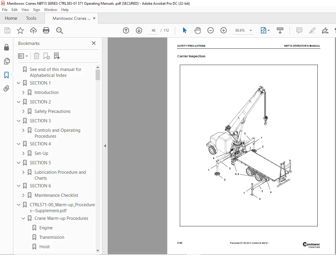
Carrier Inspection 46
SECTION 3 49
Controls and Operating Procedures 49
Crane Software Overview 49
RCL system description 49
Truck Cab Controls 50
Ignition Switch 50
Power Take Off 50
Manual Shift Control 50
Air Shift Control 50
Electric Shift Control 51
Power Shift Control 51
Automatic Transmissions 51
Park Brake 51
Controlling the Engine 51
Engine Speed Governor 51
Neutral Start/Safety Switch 51
Remote Control 51
Outrigger Control Box (Pendent) 53
Extend/Retract Switch 53
Outrigger Selector Switches 53
Center Front Stabilizer Switch 53
Crane Level Indicators 53
Crane Remote Control 54
Crane Remote Control Functions 55
Power/Emergency Stop 55
Ignition 55
Crane Power Button 55
Menu Navigation 55
Boom Control Levers 55
Boom Control – Up/Down 55
Boom Control – Telescope 55
Hoist Control 55
Hoist Enable/Speed Switch 55
Hydraulic Speed Selector Switch 55
Engine Throttle-Speed 56
Frequency Change Button 56
ON/Horn Button 56
Rated Capacity Limiter (RCL) Override button 56
Swing Control Lever 56
Boom Lift Control Lever 56
Control Levers (Optional) 56
LCD Screen Display 56
Docking Station 58
Load Charts 59
Rated Capacity Limiter (RCL) 59
Rated Capacity Limiter System (RCL) 59
Rated Capacity Limiter – Option #1 60
Rated Capacity Limiter (RCL) Override 60
Diagnostic Connector 60
Operating Procedures 61
Equipment Familiarization 61
Equipment Checks 61
Crane Start up 62
Start Up Procedure 63
Crane Remote Control Activation 63
Engine Start 63
Engine Stop 63
Crane Power 63
Control Lever 63
Frequency Receiver 63
Frequency Range 63
Crane Remote Control De-Activation 63
Batteries 64
Override Spool Limiter 64
Error Code List 65
Cold Weather Operation 66
Derated capacities for each °C below -40°C 67
Derated capacities for each °F below -40°F 67
Anti-Two-Block Check 67
Rated Capacity Limiter (RCL) Check 67
Hoist System Operation 67
Working Area 68
Single Front Outrigger-Optional 68
Work Site Location 68
Before Leaving the Truck Cab 68
Before Making the Lift 68
Load Chart 68
Using the Load Chart 68
Lifting the Load 69
Shut Down and Preparation for Road Travel 72
Directional Control Valve 73
Directional Control Valve Emergency Override 73
Unattended Crane 74
SECTION 4 75
Set-Up 75
Outrigger Setup 75
Proper Leveling of the Crane 75
Site Selection 75
Setting the Outriggers 75
Outrigger Monitoring System (OMS) (Optional—Standard in North America) 76
Lifting Over the Rear 77
Lifting Over the Front with a Front Stabilizer 77
Before Making the Lift 78
Extension Safety Information 78
Side Folding Swing Around Extension Operation 79
Deployment Procedure 79
Stowing Procedure 82
Extension Removal 83
Extension Maintenance 83
Anti-two Block Weight Installation 84
Multipart Line Reeving 84
Using Multiple Part Lines 84
Lifting a Load 84
Hoist Cable Installation 85
Wedge Sockets 85
Terminator Wedge Installation 86
Wedge Socket Installation 86
Dead-end Rigging 87
SECTION 5 89
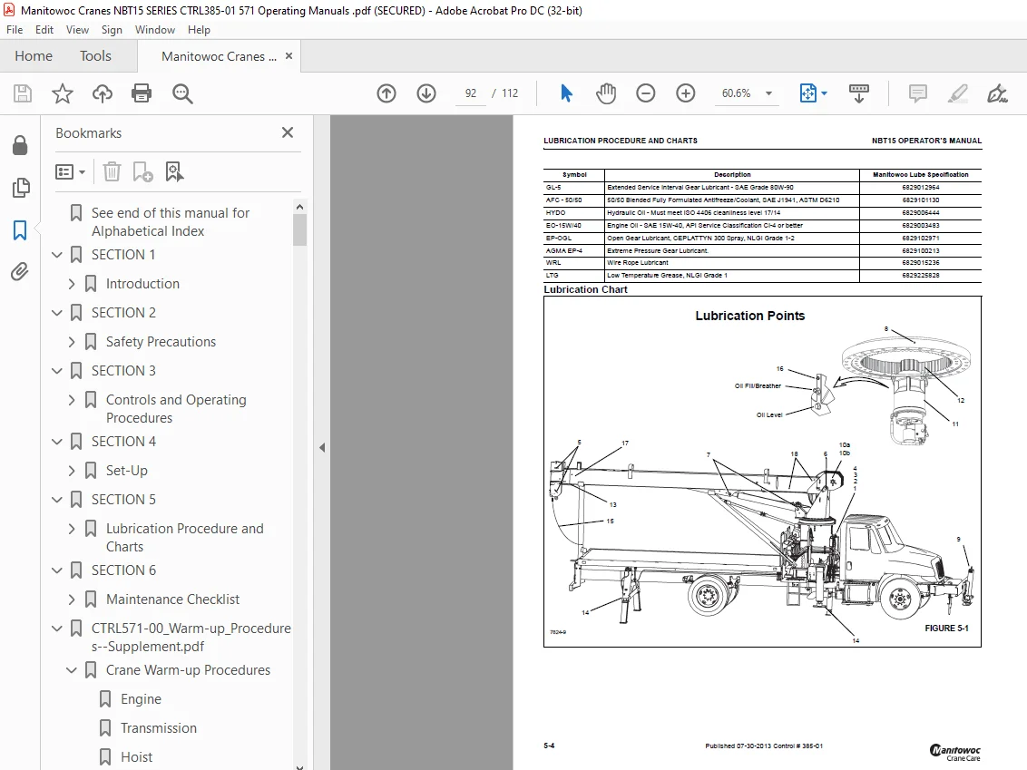
Lubrication Procedure and Charts 89
General 89
Environmental Protection 89
Lubricants 89
Arctic Conditions Below -18°C (0°F) 89
Chassis Grease 90
Extreme Pressure Multipurpose Gear Lubricant (EPGL) 90
Open Gear Lubricant 90
Chassis Grease Low Temp 90
Anti-wear Additives 90
Hydraulic Oil 90
Standard Hydraulic Oil 90
Above -12° C (10° F) 90
Intermediate Hydraulic Oil 90
-23° C to 27° C (-10° F to 80° F) 90
Wide Range Intermediate Hydraulic Oil 90
-34° C to 27° C (-30° F to 80° F) 90
Arctic Hydraulic Oil 90
-23° C and below (-10° F and below) 90
Hydraulic Oil Inspection 91
Lubrication Points 91
Surface Protection for Cylinder Rods 91
Internal Cable Sheave Lubrication 93
Inner Boom Wear Pad Lubrication 94
Side and Bottom Boom Wear Pad Lubrication 94
Hoist Brake Oil 94
Hoist Gearbox Oil 95
Hydraulic Oil Reservoir Level 95
Wire Rope Lubrication 95
SECTION 6 97
Maintenance Checklist 97
Crane Inspection and Maintenance 97
Inspections 97
Daily Inspections/Pre-use 97
Weekly Inspections 98
Monthly Inspections 98
Periodic/Annual Inspection 99
Special Boom Inspection 99
Stability 99
Hoist Cable Inspection and Maintenance 99
Keeping Records 99
Environmental Conditions 99
Dynamic Shock Loads 100
Precautions and Recommendations During Inspection 100
Inspection 100
Daily Inspections 100
Monthly Inspections 100
Periodic Inspections 100
Wire Rope Replacement 101
Care of Wire Rope 101
Replacement Cable 101
Crane Adjustments and Repairs 102
Boom Extension Cable 102
Extension Jack Service and Maintenance 102
Adding Oil to the Extension Jack 102
Changing the Extension Jack Oil 102
Lubrication – Extension Jack 102
Rust Prevention – Extension Jack 102
Hydraulic System 102
Oil Cooler 102
Tire Load and Inflation Table 102
Specifications 106
Hydraulic Pump 106
Hydraulic System 106
Reservoir 106
Hoist System 106
Crane Operating Speeds 107
Outrigger Speeds 107
CTRL571-00_Warm-up_Procedures–Supplement pdf 0
Crane Warm-up Procedures 3
Engine 3
Transmission 3
Hoist 3
Swing Drive and Turntable Bearing 3
Axles 4
Hydraulic Oil System 4
CTRL641-00_Boom Cable Tensioning-Supplement pdf 0
General 0
Cable Tensioning 0
Tensioning Setup Procedure 0
1 Mark the front of each section with a chalk line as indicated in Figure 1 0
2 Extend and retract boom several times to establish working state of cables 0
3 Extend boom so scribed lines are exposed by approximately 12 inches 0
4 Measure the extension gaps between each boom section and scribed line and note values 0
5 Retract boom so that the scribed lines are exposed by approximately 6 inches 0
6 Measure the retraction gaps between each boom section and scribed line and note values 0
7 Extend and retract the boom a few times and then repeat measuring the extension gaps 0
8 Adjust all corresponding cables according to Cable Tightening Sequence instructions 0
Figure 1 0
Cable Tension Sequence 0
Five section boom with two stage cylinder 0
1 321 retract cables 0
2 123 extend (synchronizing) cables 0
3 234 extend cables 0
4 432 retract cables 0
5 345 extend cables 0
6 543 retract cables 0
Four section boom with two stage cylinder 0
1 321 retract cables 0
2 123 extend (synchronizing) cables 0
3 234 extend cables 0
4 432 retract cables 0
Four section boom with one stage cylinder 0
1 123 extend cables 0
2 321 retract cables 0
3 234 extend cables 0
4 432 retract cables 0
Three section boom with one stage cylinder 0
1 123 extend cables 0
2 321 retract cables 0
5 – Section Boom w/ 2 Stage Cylinder Cable Positioning 0
Figure 2 0
Cable Tightening Sequence 5 Section Boom with Two Stage Extend Cylinder 0
321 and 123 cable balancing 0
Extension 0
1 Measure the extension gaps between the first and second section and the second and third section 0
2 Tighten 321 retract cable located at the front bottom of the base section the difference in the extension gap measurements 0
3 Extend and retract the boom a few times and then repeat measuring the extension gaps 0
4 Tightening until the extension gap between the first and second section and the extension gap between the second and the third are equal 0
Retraction 0
1 Measure the retraction gaps between the first and second section and the second and third section 0
2 Tighten the 123 synchronizing cable located at the back of the base section the difference in the retraction gap measurements 0
3 Extend and retract the boom a few times and then repeat measuring the retraction gaps 0
4 Tightening until the retraction gap between the first and second section and the retraction gap between the second and the third are equal 0
234 and 432 cable balancing 0
Extension 0
1 Measure the extension gaps between the third and fourth section and the second and third section 0
2 Tighten the 234 extend cable located at the back top of the second section the difference in the extension gap measurements 0
3 Extend and retract the boom a few times and then repeat measuring the extension gaps 0
4 Tightening until the extension gap between the third and fourth section is equal to the extension gap between the second and third section 0
Retraction 0
1 Measure the retraction gaps between the second and third section and the third and fourth section 0
2 Tighten the 432 retract cable located at the front bottom of the second section the difference in the retraction gap measurements 0
3 Extend and retract the boom a few times and then repeat measuring the retraction gaps 0
4 Tightening until the retraction gap between the third and fourth section is equal to the retraction gap between the second and third section 0
345 and 543 cable balancing 0
Extension 0
1 Measure the extension gaps between the fourth and fifth section and the third and fourth section 0
2 Tighten the 345 extend cable located at the back top of the third section the difference in the extension gap measurements 0
3 Extend and retract the boom a few times and then repeat measuring the extension gaps 0
4 Tightening until the extension gap between the fifth and fourth section is equal to the extension gap between the fourth and third section 0
Retraction 0
1 Measure the retraction gaps between the fourth and fifth section and the third and fourth section 0
2 Tighten the 543 retract cable located at the front bottom of the third section the difference in the retraction gap measurements 0
3 Extend and retract the boom a few times and then repeat measuring the retraction gaps 0
4 Tightening until the retraction gap between the fifth and fourth section is equal to the retraction gap between the fourth and third section 0
4- Section Boom w/ 2 Stage Cylinder Cable Positioning 0
Figure 3 0
Cable Tightening Sequence 4 Section Boom with Two Stage Extend Cylinder 0
321 and 123 cable balancing 0
Extension 0
1 Measure the extension gaps between the first and second section and the second and third section 0
2 Tighten 321 retract cable located at the front bottom of the base section the difference in the extension gap measurements 0
3 Extend and retract the boom a few times and then repeat measuring the extension gaps 0
4 Tightening until the extension gap between the first and second section and the extension gap between the second and the third are equal 0
Retraction 0
1 Measure the retraction gaps between the first and second section and the second and third section 0
2 Tighten the 123 synchronizing cable located at the back of the base section the difference in the retraction gap measurements 0
3 Extend and retract the boom a few times and then repeat measuring the retraction gaps 0
4 Tightening until the retraction gap between the first and second section and the retraction gap between the second and the third are equal 0
234 and 432 cable balancing 0
Extension 0
1 Measure the extension gaps between the third and fourth section and the second and third section 0
2 Tighten the 234 extend cable located at the back top of the second section the difference in the extension gap measurements 0
3 Extend and retract the boom a few times and then repeat measuring the extension gaps 0
4 Tightening until the extension gap between the third and fourth section is equal to the extension gap between the second and third section 0
Retraction 0
1 Measure the retraction gaps between the second and third section and the third and fourth section 0
2 Tighten the 432 retract cable located at the front bottom of the second section the difference in the retraction gap measurements 0
3 Extend and retract the boom a few times and then repeat measuring the retraction gaps 0
4 Tightening until the retraction gap between the third and fourth section is equal to the retraction gap between the second and third section 0
4- Section Boom w/ 1 Stage Cylinder Cable Positioning 0
Figure 4 0
Cable Tightening Sequence 4 Section Boom with (1) Stage Extend Cylinder 0
321 and 123 cable balancing 0
Extension 0
1 Measure the extension gaps between the first and second section and the second and third section 0
2 Tighten 123 extend cable located at the back top of the base section the difference in the extension gap measurements 0
3 Extend and retract the boom a few times and then repeat measuring the extension gaps 0
4 Tightening until the extension gap between the first and second section and the extension gap between the second and the third are equal 0
Retraction 0
1 Measure the retraction gaps between the first and second section and the second and third section 0
2 Tighten the 321 retract cable located at the front bottom of the base section the difference in the retraction gap measurements 0
3 Extend and retract the boom a few times and then repeat measuring the retraction gaps 0
4 Tightening until the retraction gap between the first and second section and the retraction gap between the second and the third are equal 0
234 and 432 cable balancing 0
Extension 0
1 Measure the extension gaps between the third and fourth section and the second and third section 0
2 Tighten the 234 extend cable located at the back top of the second section the difference in the extension gap measurements 0
3 Extend and retract the boom a few times and then repeat measuring the extension gaps 0
4 Tightening until the extension gap between the third and fourth section is equal to the extension gap between the second and third section 0
Retraction 0
1 Measure the retraction gaps between the second and third section and the third and fourth section 0
2 Tighten the 432 retract cable located at the front bottom of the second section the difference in the retraction gap measurements 0
3 Extend and retract the boom a few times and then repeat measuring the retraction gaps 0
4 Tightening until the retraction gap between the third and fourth section is equal to the retraction gap between the second and third section 0
3- Section Boom w/ 1 Stage Cylinder Cable Positioning 0
Figure 5 0
Cable Tightening Sequence 3 Section Boom with (1) Stage Extend Cylinder 0
321 and 123 cable balancing 0
Extension 0
1 Measure the extension gaps between the first and second section and the second and third section 0
2 Tighten 123 extend cable located at the back top of the base section the difference in the extension gap measurements 0
3 Extend and retract the boom a few times and then repeat measuring the extension gaps 0
4 Tightening until the extension gap between the first and second section and the extension gap between the second and the third are equal 0
Retraction 0
1 Measure the retraction gaps between the first and second section and the second and third section 0
2 Tighten the 321 retract cable located at the front bottom of the base section the difference in the retraction gap measurements 0
3 Extend and retract the boom a few times and then repeat measuring the retraction gaps 0
4 Tightening until the retraction gap between the first and second section and the retraction gap between the second and the third are equal 0
Figure 6 0
Cable Retention 0
TORQUE VALUES for Second Nut: 0
Customer Support: [email protected]
S.V