Description
Manuel d’Entretien Thermo King SR51C V227 100% Air Frais – TK 61988-3-MM-FR Révision C 2022
Ce Manuel d’Entretien Thermo King SR51C V227 100% Air Frais est le document de référence complet pour la maintenance de l’unité de toit ShuttleAIRE SR51C FA 100% 1004 (V227) équipant les bus. Référencé TK 61988-3-MM-FR, publié en Révision C (juillet 2022), ce manuel de 116 pages en français couvre l’ensemble des systèmes de climatisation, de chauffage et de contrôle électrique propres à cette unité, y compris la variante spécifique RATP identifiée par le kit 600903.
- Type de document : Manuel d’entretien (Maintenance Manual)
- Marque / Modèle : Thermo King SR51C FA 100% 1004 (V227), unité ShuttleAIRE pour bus
- Langue : Français
- Nombre de pages : 116
- Format du fichier : PDF
- Numéro de document : TK 61988-3-MM-FR
- Révision : C
- Date de publication : Juillet 2022 (25 juillet 2022)
Chapitres Couverts par ce Manuel d’Entretien Thermo King SR51C
- Précautions de sécurité (risques électriques, haute tension, retrait de la batterie, liquide de refroidissement, premiers secours)
- Systèmes modèles et tableaux d’options
- Spécifications (réfrigérant, contrôles de réfrigérant, système électrique, compresseur, poids et dimensions)
- Description générale de l’unité (présentation, fonctionnalités, système de contrôle électrique, emplacements des numéros de série, théorie de fonctionnement)
- Description technique et fonctionnelle (équipement de climatisation, gestion de sécurité du compresseur électronique, électrovanne, équipement de chauffage, circuit d’eau chaude, aérothermes)
- Composants de l’unité de toit (évaporateur, capteur antigivrage, ventilateurs de condenseur)
- Commandes et fonctionnement de l’unité (interface du pilote, affichage du tableau de bord, profils de confort thermique conducteur/passager, modes refroidissement/ventilation/chauffage)
- Graphiques et tableaux (courbes des compresseurs, CCTP RATP)
- Calendrier d’inspection de maintenance (intervalles mensuel, trimestriel, semestriel, annuel, 2 ans, 3 ans)
- Entretien électrique (câblage, HPCO, LPCO, pompe de suralimentation, vanne de liquide de refroidissement, ventilateurs de condenseur/évaporateur, servomoteur du registre d’air frais)
- Entretien du réfrigérant (sécurité, équipement de service CVC, positions des vannes de service, raccordements du collecteur de jauge, utilisation d’azote)
- Dépose et pose de composants (soupape de décharge haute pression, réservoir récepteur, filtre déshydrateur, serpentin de condenseur, évaporateur, transducteurs de pression, détendeur)
- Diagnostic et analyse de la climatisation, schémas de réfrigération
- Graphiques température-pression
- Appendice (accessoires, documentation recommandée)
- Schémas de câblage et schémas électriques
Dans son ensemble, ce document fournit au technicien tout ce qu’il faut savoir pour diagnostiquer, entretenir et réparer correctement l’unité de toit SR51C V227 : valeurs de tarage des composants de sécurité, spécifications du compresseur Bock, procédures de dépose/pose des éléments du circuit frigorifique, logique de fonctionnement du confort thermique conducteur/passager, et calendrier d’entretien préventif coordonné avec la maintenance du bus.
Complete PDF Bookmark Tree
Complete Bookmarks
The complete bookmarks in the “Manuel d'Entretien Thermo King SR51C V227 100% Air Frais – TK 61988-3-MM-FR Révision C 2022” are as follows:
+Safety Precautionsp. 11
Danger, Warning, Caution, and Noticep. 11
General Practicesp. 11
+Electrical Hazardsp. 13
Electrical Precautionsp. 13
High Voltagep. 14
Battery Removalp. 16
Engine Coolant Hazardsp. 16
Refrigerant Hazardsp. 16
Refrigerant Oil Hazardsp. 17
First Aidp. 19
+Model Systemsp. 20
Option Tables (abridged)p. 20
+Specificationp. 22
Refrigerantp. 22
Refrigerant Controlsp. 23
Electrical Systemp. 24
Compressor Specificationp. 25
Weight & Dimensionsp. 26
Solder Applicationsp. 27
+General Descriptionp. 28
Unit Overviewp. 28
Featuresp. 28
Electrical Control Systemp. 28
Serial Number Locationsp. 28
Theory of Operationp. 29
Photos and Illustrationsp. 32
+Technical and Functional Descriptionp. 37
+Air Conditioning Equipmentp. 37
Cooling Circuit 12 mp. 37
+Safety Management of eCompressor & Compressor Recommendationsp. 37
Safety Management for Electric Compressorp. 37
List of Recommendations for Compressorp. 37
+Controlling of Compressor and Solenoid Valve Functionsp. 37
Controlling Compressor Activation and Speed Functionsp. 37
Solenoid Valve (Liquid Line Between Compressor and Roof Unit)p. 38
Maintenancep. 39
+Heating Equipmentp. 40
Hot Water Circuitp. 40
Hybrid Heaterp. 41
+Pumps, Sensors and Air Heatersp. 42
Circulation Pumps and Solenoid Valvesp. 42
Hot Water Circuit Temperature Sensorp. 42
Floor-mounted Air Heatersp. 42
Driver Air Heaterp. 42
+Thermo King Roof Unit Componentsp. 42
Roof Unit Evaporator and Fans (EFM1,2)p. 43
Air conditioning mode – Roof unit evaporator anti-icing sensor (CTS)p. 44
Air conditioning mode – Condenser Fans (CFM1,2), speed regulation via sensor (CPS)p. 44
Heating mode – Hot water solenoid valve (MCV)p. 44
+Driver Defog Unitp. 44
Front Box Gas Solenoid Valvep. 44
Defog Unit Evaporator Anti-icing Sensorp. 44
Front Box Hot Water Actuatorp. 44
Vehicle Temperature Sensorsp. 44
Fresh Air Intakep. 45
+Driver Interfacep. 47
Location of Thermal Comfort Controlsp. 47
+Dashboard Displayp. 48
Driver Informationp. 48
Fault Lights on the Dashboardp. 49
+Thermal Comfort Operationp. 50
Automatic Activation Procedurep. 50
Driver and passenger Thermal Comfort Profilep. 50
Passengers – Closed Loop Control System & Restrictionsp. 51
+Passengers – Definition of Thermal Comfort Modesp. 52
Cooling Modep. 54
Ventilation Modep. 54
Heating Modep. 55
+Passengers – Controlling Room Air Distributionp. 55
Activation of 100% Air Renewal Mode (5min Delay)p. 55
Automatic Air Renewal Modep. 56
Driver Compartment – Manual Controlsp. 56
Driver Compartment – Defogging / Defrosting Modep. 56
Driver Compartment – Selection and Display of the Driver Temperature Setpointp. 57
Driver Compartment – Automatic Regulationp. 58
+Driver compartment – Closed Loop Control System Detailsp. 59
Heating Modep. 59
Air Conditioning Modep. 60
+Graphs and Tablesp. 61
Air Conditioning Compressor Graphsp. 61
CCTP RATP Thermal Comfort Initial Requestp. 63
Description of Driver's Setpoint Displayp. 63
+Maintenance Inspection Schedulep. 67
Intervalsp. 67
Refrigeration/Heatingp. 68
Compressorp. 68
Electricalp. 69
Structuralp. 69
+Electrical Maintenancep. 70
Wiring and Harness Inspectionp. 70
+High Pressure Cutout Switch (HPCO)p. 70
+Low Pressure Cutout Switch (LPCO)p. 71
+LPCO Removal and Installation (Located on Compressor)p. 71
Removalp. 71
Installationp. 72
Boost Pumpp. 72
+Coolant Valvep. 72
Removalp. 72
Installationp. 72
+Condenser Fan Maintenancep. 73
Removalp. 73
Motor Test Procedurep. 73
Installationp. 73
+Evaporator Blower Maintenancep. 73
Motor Test Procedurep. 73
Removalp. 74
Installationp. 74
+Fresh Air Damper Servomotorp. 74
Removalp. 75
Installationp. 75
+Refrigerant Maintenancep. 77
+Safetyp. 77
Refrigerant Service Safety Proceduresp. 77
General Refrigerant Handling Proceduresp. 77
PAG and POE Oil Handling Proceduresp. 78
+HVAC Service Equipmentp. 78
Evacuation Equipment Checkoutp. 78
Service Valve Positionsp. 79
+Gauge Manifold Connectionsp. 80
Before You Proceedp. 80
Gauge Manifold Positionsp. 80
Gauge Connections: Balancing Pressure, Removing Refrigerant, and Charging Systemp. 81
+Using Pressurized Nitrogenp. 82
Safety Precautionsp. 82
Procedurep. 83
+High Pressure Relief Valve Removal and Installationp. 84
Removalp. 84
Installationp. 85
+Receiver Tank Removal and Installationp. 85
Removalp. 85
Installationp. 86
+Filter-Drier Removal and Installationp. 86
Removalp. 86
Installationp. 86
+Condenser Coil Removal and Installationp. 87
Removalp. 87
Installationp. 87
+Evaporator/Heater Coil Removal and Installationp. 88
Removalp. 88
Installationp. 88
High Pressure Cutout Switch (HPCO)p. 89
+Low Pressure Cutout Switch (LPCO)p. 89
+LPCO Removal and Installation (Located on Compressor)p. 89
Removalp. 89
Installationp. 89
+Pressure Transducersp. 90
Testing Pressure Transducerp. 90
+Discharge Pressure Transducer Removal/Installationp. 90
Removalp. 90
Installationp. 90
+Suction Pressure Transducer Removal/Installationp. 91
Removalp. 91
Installationp. 91
+Expansion Valve without Strainer – Solder Typep. 91
Removalp. 91
Installationp. 91
Sensor Bulb Contactp. 92
Superheat Measurement and Adjustmentp. 92
+Structural Maintenancep. 94
+Unit Compressor and Electric Motor Mounting Boltsp. 94
+Evaporator, Heater and Condenser Coil Inspection and Cleaningp. 94
Quarterly Cleaningp. 94
Monthly Cleaningp. 94
Drain Linesp. 94
Coolant Antifreeze in Heating Unitsp. 95
Return Air Filter (Internal)p. 95
+Air Conditioning Diagnosis and Analysisp. 96
Analysis Overviewp. 96
+Air Conditioning Diagnosisp. 96
Typical Operating Pressuresp. 97
System Analysisp. 97
Troubleshooting Compressor Suction and Discharge Pressuresp. 99
Temperature-Pressure Chartsp. 100
+Appendixp. 103
Accessories Documentationp. 103
Recommended Publicationsp. 103
Diagram Indexp. 104
Ce que ce Manuel d’Entretien Thermo King SR51C Vous Permet de Faire
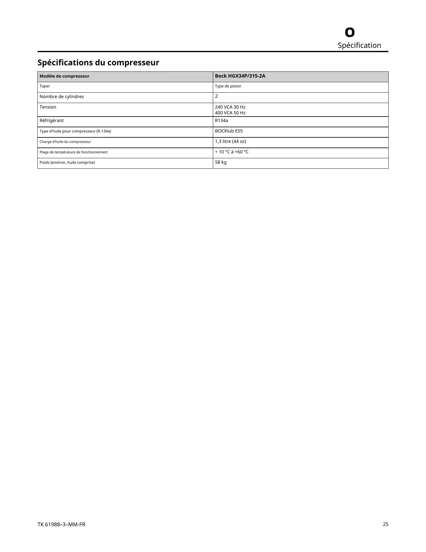
Avec ce Manuel d’Entretien Thermo King SR51C V227 100% Air Frais en main, vous pouvez vérifier la charge de réfrigérant R134a (3,9 kg recommandés), contrôler les seuils d’ouverture/fermeture du HPCO, du LPCO, du pressostat de condenseur (CPS) et de la soupape de décharge haute pression, tester et remplacer les transducteurs de pression, intervenir sur le compresseur Bock HGX34P/315-2A (huile BOCKlub E55, charge 1,3 litre), déposer et reposer le filtre déshydrateur, le réservoir récepteur, le serpentin de condenseur et l’évaporateur, ainsi qu’entretenir les ventilateurs de condenseur/évaporateur et le servomoteur du registre d’air frais. Le respect des procédures et des valeurs exactes indiquées dans ce Manuel d’Entretien Thermo King SR51C protège la garantie du fabricant et évite les dommages au compresseur ou au circuit de réfrigération. Une fois votre achat effectué, le fichier PDF est livré instantanément par téléchargement — aucune expédition, aucune attente. Consultez-le sur ordinateur, tablette ou smartphone, ou imprimez les pages dont vous avez besoin directement à l’atelier.


Reviews
There are no reviews yet.