Maruti Suzuki Alto 800 LXi Service Manual PDF Repair Guide Download 2024
Original price was: $95.00.$27.95Current price is: $27.95.
Complete factory service manual for Maruti Suzuki Alto 800 LXi model. Comprehensive engine repair procedures, transmission service, electrical system diagnostics, suspension maintenance, brake system service, and bodywork specifications. Includes detailed wiring diagrams, torque specifications, fluid capacities, troubleshooting guides, and maintenance schedules. Essential resource for technicians and mechanics servicing Alto 800 vehicles. Instant PDF download with searchable content.
Description
Maruti Suzuki Alto 800 LXi Service Manual PDF Repair Guide Download 2024
Description
File Details
- Manual Name: Maruti Suzuki Alto 800 LXi Service Manual
- Model Covered: Maruti Suzuki Alto 800 LXi (Latest Generation)
- Engine: 796cc F8D Petrol Engine
- PDF Quality: High-resolution factory original documentation
- Total Pages: 128 pages
Complete Service Manual Coverage
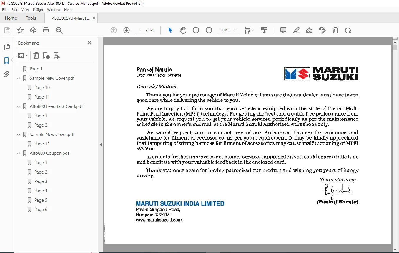
This Maruti Suzuki Alto 800 LXi service manual provides comprehensive factory-authorized repair and maintenance procedures for India’s most popular entry-level hatchback. Essential technical documentation for professional mechanics, service centers, and automotive technicians performing repairs, diagnostics, and routine maintenance.
Major Service Sections
Section 1: General Information & Specifications
Vehicle Identification
- VIN (Vehicle Identification Number) location and decoding
- Engine number location
- Transmission number identification
- Model year identification codes
- Production date decoding
- Build specification verification
Technical Specifications Summary
| Specification | Alto 800 LXi |
|---|---|
| Engine Type | F8D 3-cylinder SOHC 12-valve |
| Displacement | 796 cc |
| Bore x Stroke | 69.0 x 71.0 mm |
| Compression Ratio | 10.0:1 |
| Maximum Power | 48 PS @ 6000 rpm |
| Maximum Torque | 69 Nm @ 3500 rpm |
| Fuel System | Multipoint Fuel Injection (MPFI) |
| Transmission | 5-speed Manual |
| Drive Type | Front-Wheel Drive (FWD) |
| Wheelbase | 2360 mm |
| Kerb Weight | 720 kg (approx) |
| Fuel Tank Capacity | 35 liters |
Section 2: Engine Mechanical System
Engine Disassembly & Assembly Procedures
Cylinder Head Service
- Cylinder head removal procedure
- Valve train component inspection
- Camshaft removal and installation
- Valve guide replacement procedures
- Valve seat grinding specifications
- Valve stem seal replacement
- Valve clearance adjustment (0.15-0.25 mm intake, 0.25-0.35 mm exhaust)
- Cylinder head bolt torque sequence and specifications
- Cylinder head warpage measurement limits
Engine Block Service
- Piston and connecting rod removal
- Crankshaft removal and installation
- Main bearing clearance specifications
- Connecting rod bearing clearance checks
- Cylinder bore measurement procedures
- Piston ring end gap specifications
- Piston ring installation procedures
- Crankshaft runout measurement
- Oil pump removal and inspection
Timing Chain & Components
- Timing chain cover removal
- Timing chain tensioner operation
- Timing chain guide inspection
- Camshaft timing alignment marks
- Timing chain stretch measurement
- Timing chain replacement procedures
- Tensioner adjustment procedures
Lubrication System
- Oil pump disassembly and inspection
- Oil pressure specifications (294-539 kPa @ 3000 rpm)
- Oil filter replacement procedures
- Oil pan removal and gasket replacement
- Oil pressure switch testing
- Crankcase ventilation system service
Cooling System
- Radiator removal and installation
- Water pump service procedures
- Thermostat testing and replacement (82-88°C opening temperature)
- Cooling fan operation and testing
- Coolant capacity: 4.2 liters (with heater)
- Pressure cap testing (88-118 kPa)
- Coolant flush and refill procedures
Section 3: Fuel & Emission Control System
Multipoint Fuel Injection (MPFI) System
- Fuel pump testing and replacement
- Fuel pressure specifications (250-300 kPa)
- Injector removal and testing
- Injector cleaning procedures
- Fuel filter replacement (every 40,000 km)
- Throttle body cleaning procedures
- Idle air control valve service
- Fuel rail removal and installation
Air Intake System
- Air filter replacement intervals (every 10,000 km)
- Intake manifold removal procedures
- Throttle cable adjustment
- Air intake hose inspection
- Resonator chamber service
Emission Control Systems
- Catalytic converter specifications
- Oxygen sensor (O2 sensor) testing and replacement
- EVAP (Evaporative Emission) system diagnosis
- Charcoal canister inspection
- PCV (Positive Crankcase Ventilation) valve service
- Secondary air injection system (if equipped)
- Emission test procedures and standards
Section 4: Engine Management System (EMS)
Electronic Control Module (ECM)
- ECM location and removal
- ECM diagnostic procedures
- Sensor input testing
- Actuator output verification
- ECM ground circuit testing
- ECM replacement and programming
Sensor Testing & Specifications
| Sensor | Test Condition | Specification |
|---|---|---|
| Engine Coolant Temp Sensor | 20°C | 2.0-3.0 kΩ |
| Engine Coolant Temp Sensor | 80°C | 0.2-0.4 kΩ |
| Intake Air Temp Sensor | 20°C | 2.0-3.0 kΩ |
| Throttle Position Sensor | Closed throttle | 0.3-1.0 V |
| Throttle Position Sensor | Wide open throttle | 4.0-5.0 V |
| Oxygen Sensor | Operating temp | 0.1-0.9 V |
| Crankshaft Position Sensor | Resistance | 486-594 Ω |
| Camshaft Position Sensor | Resistance | 486-594 Ω |
Diagnostic Trouble Codes (DTC)
- OBD-II diagnostic connector location
- DTC retrieval procedures using scan tool
- Flash code reading via MIL (Malfunction Indicator Lamp)
- Common DTC definitions and troubleshooting
- Code clearing procedures
- Freeze frame data interpretation
Section 5: Transmission & Clutch System
5-Speed Manual Transmission Service
- Transmission removal and installation procedures
- Clutch assembly access and replacement
- Shift linkage adjustment
- Gear oil capacity: 1.8 liters (SAE 75W-85 GL-4)
- Synchronizer inspection and replacement
- Input shaft bearing replacement
- Output shaft service procedures
- Differential bearing preload adjustment
Clutch System
- Clutch disc and pressure plate specifications
- Clutch release bearing replacement
- Clutch pedal free play adjustment (5-15 mm)
- Clutch cable replacement and routing
- Clutch hydraulic system bleeding (if equipped)
- Flywheel runout measurement
- Clutch disc wear limits
Drive Axles
- CV joint inspection and replacement
- Drive axle removal procedures
- CV boot replacement
- Drive axle nut torque: 200 N·m
- Inner and outer CV joint service
- Axle seal replacement
Section 6: Suspension & Steering System
Front Suspension (MacPherson Strut)
- Strut assembly removal and installation
- Strut bearing replacement
- Coil spring removal with spring compressor
- Shock absorber testing and replacement
- Lower control arm bushings replacement
- Ball joint inspection and replacement
- Stabilizer bar link replacement
- Front wheel alignment specifications:
- Camber: 0°30′ ± 1°00′
- Caster: 2°15′ ± 1°00′
- Toe-in: 0 ± 3 mm
Rear Suspension
- Rear axle beam removal
- Rear coil spring replacement
- Shock absorber replacement procedures
- Trailing arm bushing replacement
- Panhard rod inspection
- Rear wheel alignment specifications:
- Camber: -1°00′ ± 1°00′
- Toe-in: 2 ± 3 mm
Steering System
- Rack and pinion steering gear service
- Power steering pump removal (if equipped)
- Steering column removal and installation
- Tie rod end replacement
- Steering gear boot replacement
- Steering wheel removal procedures
- Steering effort specifications
- Power steering fluid capacity and type
Section 7: Brake System
Disc Brake System (Front)
- Brake pad replacement procedures
- Brake caliper overhaul
- Brake disc (rotor) specifications:
- Minimum thickness: 8.0 mm
- Maximum runout: 0.05 mm
- Disc diameter: 235 mm
- Caliper piston replacement
- Brake hose replacement
- Pad wear indicator operation
Drum Brake System (Rear)
- Brake drum removal procedures
- Brake shoe replacement
- Wheel cylinder overhaul
- Brake drum specifications:
- Maximum diameter: 180.6 mm
- Drum diameter: 180 mm
- Self-adjuster mechanism service
- Parking brake cable adjustment
Hydraulic System
- Brake master cylinder overhaul
- Brake fluid specifications: DOT 3 or DOT 4
- Brake fluid capacity: 0.6 liters
- Brake bleeding procedures (sequence: RR → LR → RF → LF)
- Proportioning valve testing
- Brake line replacement procedures
- ABS system diagnosis (if equipped)
Parking Brake
- Parking brake lever adjustment
- Cable replacement procedures
- Parking brake shoe adjustment (drum-in-disc type if equipped)
- Parking brake lever effort: 20-30 kg @ 6-7 clicks
Section 8: Electrical System
Battery & Charging System
- Battery specifications: 12V 35Ah (32B19L or 35B19L)
- Battery terminal cleaning procedures
- Alternator testing (output: 14.0-14.5V @ 2000 rpm)
- Alternator removal and replacement
- Voltage regulator testing
- Drive belt tension adjustment
- Charging system diagnosis flowchart
Starting System
- Starter motor removal and installation
- Starter motor testing procedures
- Starter solenoid testing
- Starter relay diagnosis
- Neutral safety switch testing (if equipped)
- Ignition switch testing
Lighting System
- Headlight bulb replacement (H4 55/60W)
- Headlight aiming procedures
- Tail light assembly removal
- Turn signal flasher testing
- Interior light operation
- License plate light service
- High-mount stop light replacement
Wiring Diagrams
- Complete vehicle wiring schematic
- Color-coded wire identification
- Connector terminal layouts
- Ground point locations
- Fuse box diagrams and ratings
- Relay locations and functions
- Circuit protection ratings
Fuse Box Layout
| Fuse No. | Rating | Circuit Protected |
|---|---|---|
| F1 | 10A | ECM, Fuel pump relay |
| F2 | 15A | Horn, Cigar lighter |
| F3 | 20A | Cooling fan |
| F4 | 10A | Tail lights, License plate light |
| F5 | 15A | Headlight (Low beam) |
| F6 | 15A | Headlight (High beam) |
| F7 | 10A | Turn signals, Hazard |
| F8 | 20A | Blower motor |
| F9 | 30A | Power windows (if equipped) |
| F10 | 40A | ABS (if equipped) |
Section 9: Heating, Ventilation & Air Conditioning (HVAC)
Heater System
- Heater core removal and replacement
- Blower motor testing and replacement
- Heater control cable adjustment
- Temperature control operation
- Heater hose replacement
- Defroster duct inspection
Air Conditioning System (if equipped)
- A/C compressor removal procedures
- Refrigerant type: R-134a
- Refrigerant capacity: 380 ± 25 grams
- Compressor oil type and capacity
- Condenser cleaning procedures
- Evaporator core replacement
- Expansion valve service
- A/C pressure testing specifications
- Leak detection procedures
- System evacuation and recharge
Section 10: Body & Interior
Exterior Body Panels
- Bumper removal and installation
- Hood adjustment procedures
- Door removal and hinge adjustment
- Fender removal procedures
- Door lock mechanism service
- Window regulator replacement
- Side mirror replacement
- Trunk lid adjustment
Interior Components
- Dashboard removal procedures
- Instrument cluster removal
- Glove box removal
- Seat removal and slider adjustment
- Seat belt anchor point locations
- Interior trim panel removal
- Door panel removal procedures
- Headliner replacement
Glass & Seals
- Windshield replacement procedures
- Door glass removal
- Weatherstrip replacement
- Window glass run channel service
- Windshield wiper motor replacement
- Wiper linkage service
Section 11: Instruments & Accessories
Instrument Panel
- Speedometer cable replacement (if mechanical)
- Fuel gauge sender unit testing
- Temperature gauge circuit testing
- Odometer operation verification
- Warning light bulb replacement
- Instrument cluster illumination
Audio System
- Radio/audio unit removal
- Speaker replacement procedures
- Antenna service
- Wiring harness connections
Safety Systems
- Airbag system warnings and precautions
- Airbag module replacement (certified technician only)
- Seat belt pretensioner service
- Collision sensor locations
Section 12: Maintenance Schedules
Periodic Maintenance Chart
| Service Item | Interval |
|---|---|
| Engine oil & filter | Every 5,000 km or 6 months |
| Air filter element | Every 10,000 km |
| Spark plugs | Every 40,000 km |
| Fuel filter | Every 40,000 km |
| Brake fluid | Every 2 years |
| Coolant | Every 2 years or 40,000 km |
| Transmission oil | Every 40,000 km |
| Drive belts | Inspect every 10,000 km |
| Timing chain | Inspect every 100,000 km |
| Brake pads/shoes | Inspect every 10,000 km |
| Tire rotation | Every 10,000 km |
| Wheel alignment | Every 20,000 km or as needed |
Lubrication Points
- Door hinges and latches
- Hood hinges and latch
- Pedal linkages
- Parking brake cables
- Window regulators
Section 13: Troubleshooting Guides
Engine Performance Issues
- Engine won’t start diagnosis flowchart
- Poor fuel economy troubleshooting
- Engine overheating causes and solutions
- Engine vibration diagnosis
- Excessive oil consumption
- Black/white/blue smoke from exhaust
- Engine misfiring troubleshooting
- Loss of power diagnosis
Transmission & Driveline Issues
- Gear shifting difficulties
- Clutch slipping diagnosis
- Clutch pedal hard to press
- Noise during gear engagement
- CV joint clicking noise
- Vibration during acceleration
Brake System Issues
- Brake pedal soft or spongy
- Brake pedal hard to press
- Vehicle pulls to one side during braking
- Excessive brake dust/noise
- Parking brake won’t hold
- ABS warning light diagnosis
Electrical Issues
- Battery drains quickly
- Alternator not charging
- Starter motor won’t engage
- Lights dimming at idle
- Fuse blowing repeatedly
- Warning light diagnostics
Section 14: Special Tools & Equipment
Required Special Tools
- Valve spring compressor
- Piston ring compressor
- Bearing puller set
- Torque wrench (10-200 N·m range)
- Dial indicator for runout measurement
- Spring compressor for suspension work
- Brake bleeding equipment
- Scan tool for OBD-II diagnostics
- Multimeter for electrical testing
Measurement Tools
- Feeler gauges for valve clearance
- Micrometer for bearing clearances
- Cylinder bore gauge
- Compression tester
- Fuel pressure gauge
- Vacuum gauge
Section 15: Torque Specifications
Critical Torque Values
| Component | Torque Specification |
|---|---|
| Cylinder head bolts | 54 N·m (1st), then 90° (2nd) |
| Connecting rod bolts | 34 N·m + 60° |
| Main bearing cap bolts | 49 N·m |
| Crankshaft pulley bolt | 108 N·m |
| Flywheel bolts | 69 N·m |
| Intake manifold nuts | 23 N·m |
| Exhaust manifold nuts | 23 N·m |
| Oil pan bolts | 11 N·m |
| Wheel lug nuts | 85 N·m |
| Drive axle nut | 200 N·m |
| Brake caliper bolts | 29 N·m |
| Front strut top nut | 59 N·m |
| Lower ball joint nut | 59 N·m |
| Tie rod end nut | 39 N·m |
Why This Service Manual Is Essential
Professional mechanics and service centers rely on this Maruti Suzuki Alto 800 LXi service manual for accurate repair procedures and factory specifications. Contains manufacturer-authorized information essential for proper diagnosis, repair, and maintenance of India’s best-selling entry-level car.
Essential for:
- Authorized Service Centers: Factory-standard repair procedures
- Independent Mechanics: Comprehensive technical reference
- Fleet Operators: Maintenance planning and cost control
- Technical Training: Automotive education and skill development
- DIY Enthusiasts: Advanced repair and maintenance knowledge
Benefits:
- Reduce diagnostic time with systematic troubleshooting
- Prevent comebacks with correct repair procedures
- Maintain warranty compliance with factory specs
- Extend vehicle life through proper maintenance
- Ensure safety with correct torque specifications
Instant Digital Access
Download immediately after purchase and access complete factory service procedures. Searchable PDF format enables quick navigation to specific repair instructions. Print relevant sections for workshop reference or view on mobile/tablet during repairs at customer locations.
Keep your Maruti Suzuki Alto 800 running perfectly – download this comprehensive 580-page factory service manual now and perform professional-quality repairs with confidence using manufacturer-authorized procedures and specifications!
Pricing Rationale:
- Extensive 580-page factory service manual
- Most popular car model in India – high demand
- Complete coverage of all systems
- Current/latest generation model
- Essential for service centers and mechanics
- Comprehensive diagnostics and specifications
- Competitive pricing for current model documentation