Description
Massey Ferguson 5400 Series Workshop Service Manual
The Massey Ferguson 5400 Series 5425 5435 5445 5455 5460 5465 Workshop Service Manual PDF is a comprehensive technical reference for servicing and repairing the Massey Ferguson 5400 tractor range covered by publication 3378545M1. The manual identifies the six tractor models individually and develops their service information across mechanical, hydraulic, electrical and electronic systems. Its material ranges from tractor specifications and capacities through detailed component removal, dismantling, adjustment, reassembly, testing and diagnostic procedures.
Massey Ferguson 5400 Workshop S…
This workshop manual is structured for practical service work. Procedures are supported by sectional drawings, exploded views, hydraulic layouts, electrical diagrams, adjustment illustrations, component identification and tightening information. The manual also identifies special service tools where required and includes dimensions for locally made tools in relevant sections.
Models and Systems Covered
Coverage is specifically provided for 5425, 5435, 5445, 5455, 5460 and 5465 tractors. The introductory specification material separates the models and records their engine, gearbox, rear axle, linkage, PTO, front axle, hydraulic, electronic and cab configurations. Perkins engine information includes 1104C-44, 1104C-44T and 1104C-44TA applications, together with detailed 5465 six-cylinder engine data in the engine section.
The tractor specification pages identify the GBA20 gearbox and GPA20 rear axle and distinguish mechanical reverse shuttle and Power Shuttle arrangements. The transmission chapters then go much further than general specifications, covering the input unit, Power Shuttle, Speedshift, mechanical reverse shuttle, selector mechanisms, shafts, synchronisers, creeper arrangements and the setting or shimming operations required during overhaul.
File Details
- Manual type: Workshop service manual
- Brand: Massey Ferguson
- Series: 5400
- Models: 5425, 5435, 5445, 5455, 5460, 5465
- Language: English
- Pages: 886
- File format: PDF
- Document number: 3378545M1
- Issue: 1.a
- Date: May 2004
Service Information Inside the Manual
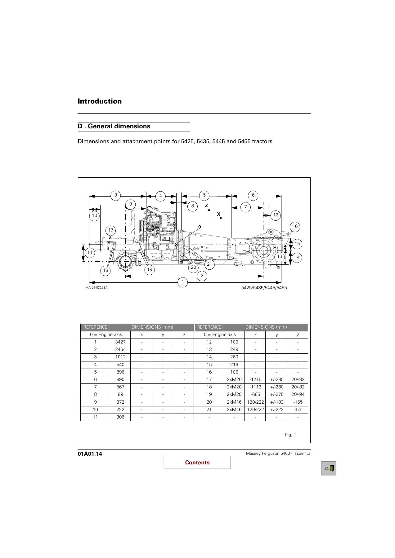
The Massey Ferguson 5400 Series 5425 5435 5445 5455 5460 5465 Workshop Service Manual PDF begins with model specifications, ground-speed data, tractor dimensions, capacities, conversion information and guidance on locking compounds and sealants. The engine material provides Perkins engine characteristics and fluid standards, including model-specific engine data, injection equipment, compression information, valve clearances and cooling-system values.
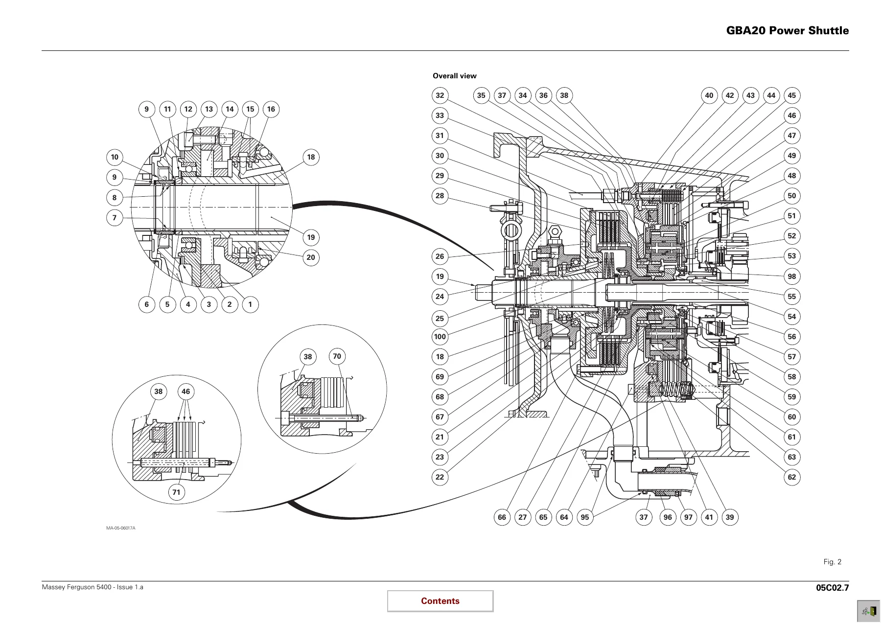
Transmission coverage is especially detailed. The GBA20 chapters explain construction and operating principles before moving into workshop procedures. Power Shuttle material covers forward and reverse clutch assemblies, hydraulic operation, dismantling, rebuilding and clutch shimming. Speedshift coverage explains the epicyclic gear train and hydraulic control, then provides procedures for the front cover, planet carrier and hydraulic components. Mechanical reverse shuttle sections include operating kinematics, dismantling, reassembly and secondary-shaft shimming. Additional chapters cover selector covers and rails, Hare/Tortoise mechanisms, creeper controls, output shaft, mainshaft and layshaft work.
The rear axle and PTO chapters extend the manual into GPA20 centre housing, trumpet housings, brakes, handbrake, differential, hitch and rear-wheel systems. PTO material includes the intermediate shaft and driving pinions, PTO brake, removable and shiftable shaft arrangements and GSPTO. Front axle material identifies DANA AG 85, DANA AG 105CD and CARRARO 20.19 arrangements and includes axle characteristics, dimensions, identification and the GPA20 multidisc 4WD clutch.
Hydraulic information covers the open-centre system, right- and left-hand covers, trailer braking, auxiliary spool valves, lift control, pressure valves, assisted and unassisted brake master cylinders and the GBA20 Power Shuttle control unit. Dedicated test procedures provide pressure-check information for the hydraulic system rather than limiting coverage to component descriptions.
The electrical and electronics sections add extensive circuit and diagnostic information. Electrical equipment includes the fuse box, relays, cab equipment, engine equipment, transmission circuits, lighting and calculator supplies. Electronics coverage includes AUTOTRONIC 5 PowerShuttle programming and parameters, tests and diagnostics, error codes, calibration and adjustments, plus electrical diagrams. Electronic linkage chapters similarly cover description, tests, diagnostics, error codes, adjustment and wiring diagrams.
Chapters Covered
- 01 – Introduction – Spécifications
- Using the manual
- Specifications
- Ground speed
- General dimensions
- Capacities
- Conversion tables
- Locking compounds and sealants
Complete PDF Bookmark Tree
Complete Bookmarks
The complete bookmarks in the “Massey Ferguson 5400 Series 5425 5435 5445 5455 5460 5465 Workshop Service Manual PDF” are as follows:
Return to the book list
Contentsp. 1
+01 – Introduction – Spécificationsp. 3
+01A01 – Introductionp. 5
A . Using the manualp. 7
B . Specificationsp. 8
C . Ground speedp. 14
D . General dimensionsp. 18
E . Capacitiesp. 21
F . Conversion tablesp. 22
G . Locking compounds and sealantsp. 23
+03 – Enginep. 25
+03A01 – Perkins engine – Generalp. 27
A . Introductionp. 29
B . Specifications and standards concerning fuel, oil and coolantp. 29
C . Main characteristicsp. 30
+05 – Gearboxp. 37
+05A02 – General – GBA20 with Power Shuttle Operationp. 39
A . Generalp. 41
B . Construction and descriptionp. 47
C . Operationp. 48
D . Specifications of the GBA20 transmission assembly with Power Shuttlep. 50
+05B01 – GBA20 input unit with mechanical reverse shuttlep. 53
A . Generalp. 55
B . Removing and refitting the input unitp. 56
C . Service toolsp. 60
+05B02 – Input unit – GBA20 with Power Shuttlep. 61
A . Generalp. 63
B . Preliminary operationsp. 64
C . Removalp. 65
D . Refittingp. 67
E . Adjusting the progressivity sensorp. 68
F . Final operationsp. 68
G . Service toolsp. 69
+05C01 – GBA20 mechanical reverse shuttlep. 71
A . Generalp. 73
B . Operationp. 78
C . Preliminary operationsp. 80
D . Disassembling and reassembling the reverse shuttlep. 80
E . Shimming the secondary shaftp. 84
F . Final operationsp. 85
+05C02 – GBA20 Power Shuttlep. 87
A . Generalp. 89
B . Removing and refitting the forward clutchp. 99
C . Disassembling and reassembling the forward clutchp. 100
D . Shimming the forward clutchp. 104
E . Disassembling and reassembling the reverse clutchp. 105
F . Disassembling and reassembling the driving pinion – Shimming the shaftp. 110
G . Service toolsp. 114
+05D02 – GBA20 Speedshift with Power Shuttlep. 117
A . Generalp. 119
B . Operationp. 125
C . Preliminary operationsp. 127
D . Removing and disassembling the front coverp. 128
E . Removing, splitting and disassembling the planet carrier assemblyp. 130
F . Disassembling the hydraulic coverp. 132
G . Assembling the planet carrierp. 133
H . Refitting the hydraulic coverp. 134
I . Assembling the planet carrierp. 135
J . Assembling and refitting the front coverp. 136
K . Final operationsp. 137
+05E02 – Selector cover – GBA20 with Power Shuttlep. 139
A . Generalp. 141
B . Operationp. 147
C . Removing and refitting the coverp. 149
D . Disassembling and reassembling the selector mechanismsp. 153
E . Fitting and adjusting the gear linkagep. 156
+05F01 – GBA20 selector rails with mechanical reverse shuttlep. 159
A . Generalp. 161
B . Servicing guidep. 167
C . Creeper forkp. 169
D . Hare / Tortoise fork and lock- 1st /2nd – 3rd / 4th fork assembly and selector railp. 173
E . Mechanical reverse shuttle selector – Fork and selector railp. 180
F . Service toolsp. 184
+05F02 – GBA20 selector rail with Power Shuttlep. 185
A . Generalp. 187
B . Servicing guidep. 193
C . Creeper forkp. 195
D . Hare / Tortoise fork and lock- 1st /2nd – 3rd / 4th fork assembly and selector railp. 199
E . Service toolsp. 207
+05G02 – GBA20 output shaft with Power Shuttlep. 209
A . Generalp. 211
B . Preliminary operationsp. 215
C . Removing and refitting the selector rail and the forksp. 215
D . Removing, refitting and shimming the shaftp. 216
E . Final operationsp. 220
+05H02 – GBA20 mainshaft with Power Shuttlep. 221
A . Generalp. 223
B . Preliminary operationsp. 227
C . Disassembling and reassembling the shaftp. 228
D . Final operationsp. 230
E . Service toolsp. 231
+05I02 – GBA20 layshaft with Power Shuttlep. 233
A . Generalp. 235
B . Preliminary operationsp. 237
C . Removing and refitting the shaft and pinion assemblyp. 237
D . Removing and refitting pinionsp. 238
E . Replacing the taper roller bearings and the layshaftp. 239
F . Shimming the pinionsp. 239
G . Shimming the shaftp. 240
H . Final operationsp. 241
I . Service toolp. 242
+05J01 – GBA20 Creeper unitp. 243
A . Generalp. 245
B . Operationp. 245
C . Removing the creeper unit and the ring gearp. 248
D . Removing the planet carrierp. 248
E . Reassembling the planet carrier, refitting the ring gear and the unitp. 249
F . Final operationsp. 249
G . Adjusting the controlp. 250
+06 – Rear axlep. 251
+06A01 – General – GPA20 operationp. 253
A . Generalp. 255
B . Centre housing assemblyp. 255
+06B01 – GPA20 Normal Duty Trumpet housingsp. 259
A . Generalp. 261
B . Trumpet assemblyp. 264
C . Planet carrierp. 266
D . Bearings and sealsp. 267
E . Preloading the axle shaft bearingsp. 268
F . Replacing a lug studp. 269
+06B02 – GPA20 Heavy Duty Trumpet housingsp. 271
A . Generalp. 273
B . Trumpet assemblyp. 276
C . Planet carrierp. 278
D . Bearings and sealsp. 279
E . Preloading the axle shaft bearingsp. 280
F . Replacing a wheel studp. 281
+06C01 – GPA20 brake pistonp. 283
A . Generalp. 285
B . Disassemblyp. 286
C . Reassemblyp. 287
+06D01 – GPA20 handbrake unit and controlp. 289
A . Generalp. 291
B . Operationp. 291
C . Disassemblyp. 295
D . Reassemblyp. 297
E . Assembling and adjusting the controlp. 299
+06E01 – GPA20 differentialp. 301
A . Generalp. 303
B . Removing the left-hand flange and differential lock assemblyp. 307
C . Disassembling and reassembling the differential lock assemblyp. 308
D . Refitting the left-hand flange and the differential lock assemblyp. 309
E . Removing the differential assemblyp. 311
F . Disassembling the differential assembly and the ring gearp. 312
G . Removing and disassembling the drive pinionp. 313
H . Reassembling the ring gear and differential assemblyp. 314
I . Adjusting the bevel gear distance, refitting and shimming of the drive pinionp. 315
J . Refitting and shimming of the differential assemblyp. 318
K . Adjusting and checking the backlashp. 322
L . Service toolsp. 324
+06F01 – GPA20 hitch / Linkagep. 325
A . Generalp. 327
B . Removalp. 330
C . Disassemblyp. 331
D . Reassemblyp. 332
E . Refittingp. 334
F . Rear Hitchp. 336
G . Presentation of the hitchp. 336
H . Disassembling and reassembling a lift ramp. 339
+06G01 – GPA20 hitch hooksp. 341
A . Generalp. 343
B . Presentation of the different hitch hooksp. 344
C . Adjusting automatic hook tie-rods and controlsp. 347
D . Operating principle of the Dromone retractable hookp. 349
+06H01 – GPA20 rear wheels / hubsp. 351
A . Generalp. 353
B . Description of rear axle wheel assemblyp. 353
C . Changing wheel track spacingp. 354
D . Replacing a wheel studp. 356
+07 – Power take offp. 357
+07A01 – General – GPA20 operationp. 359
A . Generalp. 361
B . Existing power take-off typesp. 363
+07B01 – Intermediate shaft – Driving pinions – GPA20 brakep. 369
A . Generalp. 371
B . Operationp. 371
C . 2-speed PTO (without shimming)p. 375
D . 2-speed PTO (with shimming)p. 377
E . 4-speed economy PTO (without shimming)p. 379
F . 4-speed LSPTO (with shimming)p. 382
G . Assembling and adjusting the 4-speed LSPTO controlp. 384
+07C01 – GPA20 removable shaftp. 385
A . Generalp. 387
B . Replacing the 540 or 1000 rpm shaftp. 390
C . Removing and refitting the rear bearingp. 390
D . Disassembling and reassembling the rear bearingp. 391
E . Disassembling and assembling the 540 and 1000 rpm pinions and the front bearingp. 392
+07D01 – GPA20 shiftable shaftp. 393
A . Generalp. 395
B . Layout of components and different versionsp. 398
C . Removing and refitting the rear bearingp. 400
D . Disassembling and reassembling the rear bearingp. 401
E . Disassembling and reassembling the pinions (540 and 1000 rpm) and the front shaft bearingp. 402
F . Controlsp. 404
G . Flange shaftp. 405
H . Shaft with reinforced sealingp. 407
+07E01 – GPA20 – GSPTOp. 413
A . Generalp. 415
B . Operationp. 415
C . Disassembling the power take off (2WD version)p. 419
D . Reassembling the power take off (2WD version)p. 421
E . Disassembling the power take off (4WD version)p. 424
F . Reassembling the power take off (4WD version)p. 425
G . Assembling and adjusting the controlp. 426
+08 – Front axlep. 427
+08A01 – Generalp. 429
A . General descriptionp. 431
B . Characteristics and dimensionsp. 435
C . Product identificationp. 437
+08E01 – GPA20 multidisc 4WD clutchp. 439
A . Generalp. 441
B . Operationp. 441
C . Removing the clutch assemblyp. 445
D . Disassembling the clutchp. 446
E . Reassembling the clutchp. 447
F . Refitting the clutch assemblyp. 448
G . Locally made toolsp. 450
+09 – Hydraulicsp. 451
+09A01 – Description of circuit open centre 57 l/mnp. 453
A . Generalp. 455
B . Low flow rate, low pressure circuitp. 455
C . Layout of main components of Power shuttle and Speedshift circuitp. 457
D . Layout of main components of Mechanical reverse shuttle Speedshift circuitp. 459
E . High flow rate, high pressure circuitp. 460
F . Diagram of mechanical reverse shuttle Speedshiftp. 460
G . Diagram of Power shuttle Speedshiftp. 462
+09B01 – Right-hand cover – 57 l/min Open Centrep. 465
A . Generalp. 467
B . Identification of channels and portsp. 472
C . Removing and refitting the coverp. 474
D . Disassembling and reassembling the high pressure valvep. 477
E . Disassembling and reassembling the coverp. 478
F . Removing and refitting the pumpp. 479
G . Disassembling and reassembling the pumpp. 481
H . Adjusting the engine speed sensorp. 484
+09C01 – Left-hand cover – 57 l/min Open Centrep. 485
A . Generalp. 487
B . Removing – Refittingp. 488
+09D01 – Trailer braking – Open centrep. 491
A . Generalp. 493
B . Removing and refitting the brake spool valvep. 496
C . Operation, trailer brakes released and partial brakingp. 499
D . Partial and maximum trailer brakingp. 501
E . Version without trailer brakingp. 502
+09E01 – Auxiliary spool valvep. 503
A . Generalp. 505
B . Layout of channels and portsp. 510
C . Operating and adjusting the flow dividerp. 512
D . Removing and refitting spool valvesp. 514
E . 3-position spool valve, SA / DA with spring loaded return to neutralp. 516
F . 3-position spool valve, SA / DA with automatic return to neutralp. 518
G . 3-position SA / DA spool valve with non-return valve and automatic returnp. 520
H . 4-position DA spool valve, with automatic return to neutral and floating positionp. 522
I . Fitting and adjusting a control cablep. 524
+09F01 – Lift control spool valve – Open Centrep. 527
A . Generalp. 529
B . Layout of components and identification of portsp. 530
C . Neutral positionp. 532
D . Lifting positionp. 536
E . Lowering positionp. 538
F . Shock valvep. 540
G . Removing and refitting the spool valvep. 542
+09H01 – 17 bar – 5 bar and 1.5 bar valves – Open centrep. 545
A . Generalp. 547
B . Description of the 17 bar low pressure valvep. 549
C . Removing – refitting and disassembling – reassembling the 17 bar valvep. 551
D . Adjusting the 17 bar valvep. 552
E . Operation of the cooling systemp. 553
F . Assembling the 5 bar valvep. 554
G . Description of the 1.5 bar lubricating valvep. 554
H . Removing – refitting and disassembling – reassembling the 1.5 bar valvep. 555
+09I01 – Unassisted brake master cylindersp. 557
A . Generalp. 559
B . Layout of hydraulic linesp. 560
C . Practical servicing advicep. 564
D . Single circuit master cylinders (without trailer brake)p. 565
E . Double circuit master cylinders (with trailer brake)p. 566
F . Adjusting brake pedalsp. 568
G . Bleeding the main brake circuitp. 569
H . Bleeding the trailer brake circuitp. 571
+09I02 – Assisted brake master cylindersp. 573
A . Generalp. 575
B . Layout of hydraulic linesp. 577
C . Practical servicing advicep. 582
D . Brake master cylindersp. 583
E . FTE valvep. 585
F . Adjusting brake pedalsp. 587
G . Bleeding the main brake circuitp. 588
H . Bleeding the trailer brake circuitp. 591
+09J01 – GBA20 Power Shuttle control unitp. 593
A . Generalp. 595
B . Presentation of control unit and hydraulic linesp. 596
C . Power Shuttle controlp. 596
D . Speedshift controlp. 599
E . Explanation of Speedshift ratiosp. 601
F . Removing – Refitting the control unitp. 602
+09K01 – 57 l/min Open Centre testsp. 603
A . Generalp. 605
B . High flow rate circuitp. 606
C . Low flow rate circuitp. 611
+10 – Electrical equipmentp. 623
+10A01 – Fuse box and relaysp. 625
A . Fuse boxp. 627
B . Relays – Europep. 629
C . Relays – North Americap. 631
D . Relays – Germanyp. 633
+10A02 – GBA20 electronic equipmentp. 635
A . Generalp. 637
B . Cab equipmentp. 639
C . Engine equipmentp. 661
D . Transmissionp. 673
E . Bulb typesp. 695
F . Lightingp. 701
G . Calculator supplyp. 737
+11 – Electronicsp. 743
+11B10 – AUTOTRONIC 5 – Descriptionp. 745
A . Generalp. 747
B . Autotronic 5 status flowchartsp. 748
C . Autotronic 5 connector pin allocationp. 751
D . Automatic responses of the Autotronic 5p. 753
E . Power Shuttle principlesp. 755
+GUF511 – AUTOTRONIC 5 – PowerShuttle – Programming and setting parametersp. 757
A . Programmingp. 759
B . Setting parametersp. 764
+GUF512 – AUTOTRONIC 5 – PowerShuttle – Tests and diagnosticsp. 769
A . Autotronic 5 statusesp. 771
B . Gearbox functionp. 772
C . Power Take-Off functionp. 776
+GUF513 – AUTOTRONIC 5 – PowerShuttle – Error codesp. 779
A . Reading error codesp. 781
B . List of error codesp. 784
C . Analysing components and their error codesp. 786
D . Analysing other error codesp. 799
+GUF514 – AUTOTRONIC 5 – PowerShuttle – Calibration and adjustmentsp. 801
A . Calibrating the Power Shuttlep. 803
B . Adjusting the Power Shuttle progressive shiftingp. 806
C . Adjusting the manoeuvring pedalp. 808
D . Calibrating the (manoeuvring) clutch pedalp. 810
+GUF515 – AUTOTRONIC 5 – PowerShuttle – Electrical diagramsp. 811
A . Generalp. 813
B . Electrical diagramsp. 815
C . Layout of componentsp. 834
+11C10 – ELECTRONIC LINKAGE – Descriptionp. 837
A . Descriptionp. 839
B . Consolep. 841
C . Electronic calculator EHRB connector pin allocationp. 844
+11C12 – ELECTRONIC LINKAGE – Tests and diagnosticsp. 847
A . Electronic Linkage component testing and diagnosticsp. 849
+11C13 – ELECTRONIC LINKAGE – Error codesp. 853
A . Reading error codesp. 855
B . List of error codesp. 856
C . Analysing components and their error codesp. 857
+11C14 – ELECTRONIC LINKAGE – Adjustmentp. 869
A . Adjusting the position sensorp. 871
+11C15 – ELECTRONIC LINKAGE – Electrical diagramsp. 873
A . Generalp. 875
B . Electrical diagramsp. 877
- 03 – Engine
- Perkins engine – General
- Specifications and standards concerning fuel, oil and coolant
- Main characteristics
- 05 – Gearbox
- General – GBA20 with Power Shuttle Operation
- GBA20 input unit with mechanical reverse shuttle
- Input unit – GBA20 with Power Shuttle
- GBA20 mechanical reverse shuttle
- GBA20 Power Shuttle
- GBA20 Speedshift with Power Shuttle
- Selector cover – GBA20 with Power Shuttle
- GBA20 selector rails with mechanical reverse shuttle
- GBA20 selector rail with Power Shuttle
- GBA20 output shaft with Power Shuttle
- GBA20 mainshaft with Power Shuttle
- GBA20 layshaft with Power Shuttle
- GBA20 Creeper unit
- 06 – Rear axle
- General – GPA20 operation
- GPA20 Normal Duty Trumpet housings
- GPA20 Heavy Duty Trumpet housings
- GPA20 brake piston
- GPA20 handbrake unit and control
- GPA20 differential
- GPA20 hitch / Linkage
- GPA20 hitch hooks
- GPA20 rear wheels / hubs
- 07 – Power take off
- General – GPA20 operation
- Intermediate shaft – Driving pinions – GPA20 brake
- GPA20 removable shaft
- GPA20 shiftable shaft
- GPA20 – GSPTO
- 08 – Front axle
- General
- GPA20 multidisc 4WD clutch
- 09 – Hydraulics
- Description of circuit open centre 57 l/mn
- Right-hand cover – 57 l/min Open Centre
- Left-hand cover – 57 l/min Open Centre
- Trailer braking – Open centre
- Auxiliary spool valve
- Lift control spool valve – Open Centre
- 17 bar – 5 bar and 1.5 bar valves – Open centre
- Unassisted brake master cylinders
- Assisted brake master cylinders
- GBA20 Power Shuttle control unit
- 57 l/min Open Centre tests
- 10 – Electrical equipment
- Fuse box
- GBA20 electronic equipment
- 11 – Electronics
- AUTOTRONIC 5 – Description
- AUTOTRONIC 5 – PowerShuttle – Programming and setting parameters
- AUTOTRONIC 5 – PowerShuttle – Tests and diagnostics
- AUTOTRONIC 5 – PowerShuttle – Error codes
- AUTOTRONIC 5 – PowerShuttle – Calibration and adjustments
- AUTOTRONIC 5 – PowerShuttle – Electrical diagrams
- ELECTRONIC LINKAGE – Description
- ELECTRONIC LINKAGE – Tests and diagnostics
- ELECTRONIC LINKAGE – Error codes
- ELECTRONIC LINKAGE – Adjustment and electrical diagrams
Taken together, these chapters make the Massey Ferguson 5400 workshop manual useful for work ranging from routine technical checks to major drivetrain disassembly. Mechanical procedures are linked to measurements, clearances, shimming instructions, torque values, hydraulic pressures, electrical circuits and electronic diagnostic information, allowing the technician to follow the required sequence rather than relying only on general component descriptions.
Detailed Repair and Adjustment Procedures
Many operations are presented as step-by-step workshop sequences with preliminary operations, removal, disassembly, inspection, reassembly, adjustment and final checks. Examples within the transmission material include removing and refitting GBA20 input units, rebuilding Power Shuttle clutches, setting clutch end play, shimming shafts and synchronisers, servicing Speedshift components, adjusting selector mechanisms and checking the Hare/Tortoise range. Procedures frequently finish with oil-level checks, leak checks, functional checks or road tests where appropriate.
The same repair-oriented approach continues through the rear axle, PTO, 4WD and hydraulic sections. Differential work includes preload and backlash setting; PTO chapters cover shaft and bearing service as well as control adjustment; hydraulic sections combine component service with circuit testing. Electrical and electronics chapters provide connector, harness and circuit information together with Autotronic 5 and electronic linkage diagnostic material.
Illustrations, Exploded Views and Service Data
The manual uses extensive technical illustration to show component relationships and assembly order. GBA20 transmission sections contain cutaway views and exploded diagrams of the Power Shuttle, Speedshift, synchronisers and gearbox shafts. Rear axle, PTO and front axle chapters contain assembly drawings and component identification, while the hydraulic and electrical chapters use circuit layouts and wiring diagrams to trace system operation.
Service values are integrated into the procedures. Depending on the operation, the manual gives tightening torques, bearing preload or clearance targets, synchroniser wear checks, fork clearances, hydraulic pressure values, adjustment dimensions and other measurements needed for correct reassembly. This makes the Massey Ferguson 5400 Series 5425 5435 5445 5455 5460 5465 Workshop Service Manual PDF useful not only for identifying components but also for carrying out the settings that complete a repair.
Repair Your Massey Ferguson 5400 With the Correct Technical Reference
Use this Massey Ferguson 5400 service manual when servicing the 5425, 5435, 5445, 5455, 5460 or 5465 and you need procedures that go beyond basic maintenance information. It supports transmission overhaul, Power Shuttle and Speedshift work, rear axle and differential repair, PTO service, 4WD clutch work, hydraulic diagnosis, electrical troubleshooting, electronic testing and the many adjustment and reassembly operations associated with these systems.
Correct procedures, measurements, torque values, hydraulic pressures and adjustment data matter when components must be dismantled and returned to service accurately. The Massey Ferguson 5400 Series 5425 5435 5445 5455 5460 5465 Workshop Service Manual PDF puts that workshop information into one 886-page reference. Your manual is supplied as an instant PDF download after payment, with no shipping required. Open it on compatible computers, tablets or phones and print the pages you need for workshop use.

Reviews
There are no reviews yet.