Trusted Business
Verified & Licensed
Virus Free Files
100% Safe Downloads
Secure Payment
SSL Protected
Instant Delivery
Available Immediately
Sale!


Massey Ferguson 5400 Series Tractors Service Manual – PDF DOWNLOAD
Original price was: $53.95.$31.95Current price is: $31.95.
Massey Ferguson 5400 Series Tractors Service Manual – PDF DOWNLOAD
Instant PDF Download
Available immediately
Save to Your Device
Download & keep forever
Antivirus Scanned
100% virus-free
Trusted Worldwide
175,000+ customers
Description
Massey Ferguson 5400 Series Tractors Service Manual – PDF DOWNLOAD
FILE DETAILS:
Massey Ferguson 5400 Series Tractors Service Manual – PDF DOWNLOAD
Size: 251 MB
Pages : 2168
Format: PDF
Language: English
Brand: Massey Ferguson
Format: PDF
Language: English
Brand: Massey Ferguson
TABLE OF CONTENTS:
Massey Ferguson 5400 Series Tractors Service Manual – PDF DOWNLOAD
Introduction
1A10 5400 series tractors – General
1A11 5400 series tractors – Error codes
1A12 5400 series tractors – Fuse box, electrical diagrams, harnesses and
hydraulics diagrams
hydraulics diagrams
1A16 5400 series tractors – Adjustments, bleeding and calibrations
Separation of assemblies
2A17 Cab – Disassembly and reassembly
Engine
3A10 Sisu Tier 3 engine- General
3A13 Sisu Tier 3 engine – Layout of components
3A14 Sisu Tier 3 engine – Tests and diagnostics
3A16 Sisu Tier 3 engine- Adjustments, bleeding and calibrations
3A17 Sisu Tier 3 engine – Disassembly and reassembly
3A18 Sisu Tier 3 engine- Service tools
3810 Perkins 11040 Tier 3 mechanical engine
3820 Perkins 11040 For 3 electronic engine
Clutch
Chapter intentionally left blank
Chapter intentionally left blank
Gearbox
5A10 GBA50 — General information
5A12 GBA50 – Electrical and hydraulics diagrams
5A13 GBA50 — Layout of components
5A16 GBA50 — Adjustments, bleeding and calibrations
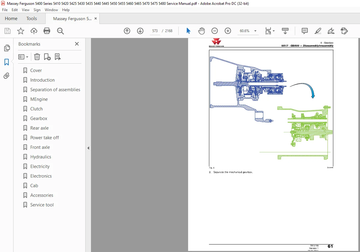
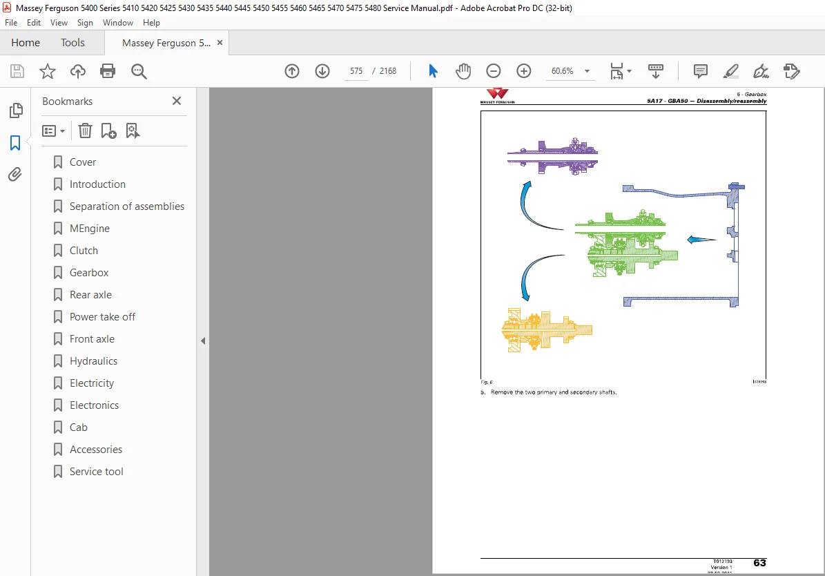
5A17 GBA50 — Disassembly/reassembly
5A20 GBASOIPower Shuttle — General information
5A22 GBA50/Power Shuttle – Electrical and hydraulics diagrams
5A23 GBA50/Power Shuttle — Layout of components
5A27 GBASOIPower Shuttle — Disassembly/reassembly
5A28 GBA50/Power Shuttle – Service tools
5A30 GBASOIPowershift module — General information
5A32 GBASOIPowershift module – Electrical and hydraulics diagrams
5A33 GBASOIPowershift module — Layout of components
5A37 GBA50/Powershift module — Disassembly/reassembly
5A38 GBA50/Powershift module — Service tools
5A40 GBA50/Robotic mechanical gearbox — General information
5A42 GBA50/Robotic mechanical gearbox – Electrical and hydraulics
diagrams
diagrams
5A43 GBA50/Robotic mechanical gearbox — Layout of components
5A4? GBA50/Robotic mechanical gearbox — Disassembly/reassembly
5A48 GBA50/Robotic mechanical gearbox — Service tools
5A60 GBASOISuper creeper gears – General
5A63 GBA50/Super creeper gears – Layout of components
SASS GBA50/Super creeper gears -Adjustments. bleeding and calibrations
SASS GBA50/Super creeper gears -Adjustments. bleeding and calibrations
5A67 GBA50/Super creeper gears – Disassembly/reassembly
5A68 GBA50/Super creeper gears – Service tools
Rear axle
6A10 GPASO — General information
6A12 GPASO – Electrical and hydraulics diagrams
6M3 GPASO – Layout of components
6A17 GPASO — Disassembly/reassembly
6A20 GPASO/Trumpet housings — General information
6A22 GPASO/Trumpet housings – Electrical and hydraulics diagrams
6A23 GPASOfi’rumpet housings— Layout of components
6A26 GPASOfTrumpet housings — Adjustments, bleeding and calibrations
6A27 GPASOfi’rumpet housings — Disassembly/reassembly
6A28 GPASO/Trumpel housings—service tools
6A30 GPASO/Rear crown wheel and pinion 9×40 and 10×42 – General
6A32 GPASO/Rear crown wheel and pinion 9×40 and 10×42 – Electrical and
hydraulics diagrams
hydraulics diagrams
6A33 GPASO/Rear crown wheel and pinion 9×40 and 10×42- Layout of
components
components
6A36 GPASO/Rear crown wheel and pinion 9×40 and 10×42 – Adjustments,
bleeding and calibrations
bleeding and calibrations
6A37 GPASOIRear crown wheel and pinion 9×40 and 10×42 –
Disassembly/reassembly
Disassembly/reassembly
6A38 GPASO/Rear crown wheel and pinion 9×40 and 10×42 – Service tools
6A40 GPASO/i’ractor braking — General information
6A42 GPASOfi‘ractor braking – Electrical and hydraulics diagrams
6A43 GPASOfTractor braking – Layout of components
6A46 GPASO/Tractor braking — Adjustments. bleeding and calibrations
6A4? GPASOITractor braking — Disassembly/reassembly
6A48 GPASO/l’ractor braking – Service tools
6A50 GPA50/Hydraulic trailer braking – General
6A52 GPASO/Hydraulic trailer braking – Electrical and hydraulics diagrams
6A53 GPA50/Hydraulic trailer braking – Layout of components
6A56 GPASO/Hydraulic trailer braking – Adjustments, bleeding and
calibrations
calibrations
6A57 GPASO/Hydraulic trailer braking – Disassembly/reassembly
6A58 GPASO/Hydraulic trailer braking – Service tools
Power take-off
7A10 GPASO/Rear PTO with two electrohydraulic speeds – General
7A12 GPASO/Rear PTO with two electrohydraulic speeds – Electrical and
hydraulics diagrams
hydraulics diagrams
7A13 GPASO/Rear PTO with two electrohydraulic speeds – Layout of
components
components
7A16 GPASO/Rear PTO with two electrohydraulic speeds – Adjustments,
bleeding and calibrations
bleeding and calibrations
7A17 GPASO/Rear PTO with two electrohydraulic speeds —
Disassembly/reassembly
Disassembly/reassembly
7A18 GPASO/Rear PTO with two electrohydraulic speeds – Service tools
7A20 GPASO/Rear PTO with three electrohydraulic speeds – General
7A22 GPASO/Rear PTO with three electrohydraulic speeds – Electrical and
hvdranlin: diam-am:
7A23 GPASO/Rear PTO with three electrohydraulic speeds – Layout of
components
hvdranlin: diam-am:
7A23 GPASO/Rear PTO with three electrohydraulic speeds – Layout of
components
7A26 GPASO/Rear PTO with three electrohydraulic speeds – Adjustment
bleeding and calibrations
bleeding and calibrations
7A27 GPASO/Rear PTO with three electrohydraulic speeds –
Disassembly/reassembly
Disassembly/reassembly
7A28 GPASO/Rear PTO with three electrohydraulic speeds – Service tool
7A30 GPASO/Rear power take-off clutch – General
7A32 GPASO/Rear power take-off clutch – Electrical and hydraulics
diagrams
diagrams
7A33 GPASOIRear power take-off clutch – Layout of components
7A37 GPASOIRear power take-off clutch – Disassembly/reassembly
7A38 GPASO/Rear power take-off clutch – Service tools
7010 Zuidberg front power take-off – General
7011 Zuidberg front power take-off – Error codes
7012 Zuidberg front power take-off— Electrical and hydraulics diagrams
7013 Zuidberg front power take-off – Layout of components
7014 Zuidberg front power take-off -Tests and diagnostics
7015 Zuidberg front power take-off- Programming and setting parameti
7016 Zuidberg front power take-off – Adjustments, bleeding and
calibrations
calibrations
7017 Zuidberg front power take-off – Disassembly and reassembly
7018 Zuidberg front power take-off – Service tools
Front axle
8A10 DANA 720 – General information
8A12 DANA 720 – Electrical and hydraulics diagrams
8A13 DANA 720 – Layout of components
8A14 DANA 720 – Tests and diagnostics
8A17 DANA 720 – Disassembly and reassembly
8A18 DANA 720 – Service tools
8310 DANA 725 – General information
8312 DANA 725 – Electrical and hydraulics diagrams
8313 DANA 725 – Layout of components
8314 DANA 725 – Tests and diagnostics
8317 DANA 725 – Disassembly and reassembly
8318 DANA 725 – Service tools
8010 DANA 730 fixed – General information
8012 DANA 730 fixed – Electrical and hydraulics diagrams
8C13 DANA 730 fixed – Layout of components
8014 DANA 730 fixed —Tests and diagnostics
8017 DANA 730 fixed – Disassembly and reassembly
8018 DANA 730 fixed – Service tools
8020 DANA 730 suspended – General information
8021 DANA 730 suspended – Error codes
8022 DANA 730 suspended – Electrical and hydraulics diagrams
8023 DANA 730 suspended – Layout of components
8024 DANA 730 suspended – Tests and diagnostics
8027 DANA 730 suspended – Disassembly and reassembly
8028 DANA 730 suspended – Service tools
SD10 DANA 735 fixed – General information
SD11 DANA 735 fixed – Error codes
8012 DANA 735 – Electrical and hydraulics diagrams
8013 DANA 735 fixed – Layout of components
8013 DANA 735 fixed – Layout of components
8014 DANA 735 fixed – Tests and diagnostics
8017 DANA 735 fixed – Disassembly and reassembly
8018 DANA 735 fixed – Service tools
8020 DANA 735 suspended – General information
8021 DANA 735 suspended – Error codes
8022 DANA 735 suspended – Electrical and hydraulics diagrams
8023 DANA 735 suspended – Layout of components
8024 DANA 735 suspended – Tests and diagnostics
8027 DANA 735 suspended – Disassembly and reassembly
8028 DANA 735 suspended – Service tools
8610 GPA50/4WD clutch – General information
8612 GPA50/4W0 clutch – Electrical and hydrauliCs diagrams
8613 6PA50/4W0 clutch – Layout of components
8616 GPASOMWD clutch – Adjustments, bleeding and calibrations
8617 GPA50/4W0 clutch – Disassembly and reassembly
8618 6PA50/4W0 clutch – Service tools
8110 Open Centre/Steering unit – General
Hydraulics
9A10 GTA5050 open centre — General
9A12 GTA5050 open centre —E|ectrical and hydraulics diagrams
9A13 GTA5050 open centre—Layout of components
9A14 GTA5050 open centre —Tests and diagnostics
9A20 GTA5050 open centre/right-hand cover plate —Genera|
9A22 GTA5050 open centre/right-hand cover plate — Electrical and
hydraulics diagrams
hydraulics diagrams
9A23 GTA5050 open centre/right-hand cover plate — Layout ofcomponents
9A27 GTA5050 open centrelright-hand cover plate —
Disassembly/reassembly
Disassembly/reassembly
9310 6TA5050100|lmin open centre—General
9312 GTA5050 100 Ilmin open centre —E|ectrica| and hydraulics diagrams
9313 GTA5050 100 Ilmin open centre — Layout of components
9314 GTA5050 100 Ilmin open centre —Tests and diagnostics
9320 GTA5050 100 Ilmin open centre/right-hand cover plate—General
9322 GTA5050 100 Ilmin open centre/right—hand cover plate—Electrical
and hydraulics diagrams
and hydraulics diagrams
9323 GTA5050 100 Ilmin open centre/right-hand cover plate—Layout of
components
components
9327 GTA5050 100 Ilmin open centre/right—hand cover plate —
Disassembly/reassembly
Disassembly/reassembly
9330 GTA5050 100 Ilmin open centre/left-hand cover plate – General
9332 GTA5050 100 Ilmin open centrefleft-hand cover plate — Electrical and
hydraulics diagrams
hydraulics diagrams
9333 GTA5050 100 Ilmin open centre/left-hand cover plate — Layout of
components
components
9337 GTA5050 100 Ilmin open centre/left-hand cover plate—
Disassembly/reassembly
Disassembly/reassembly
9010 GTA5050 open centre/spool valves — General
9012 GTA5050 open centre/spool valves — Electrical and hydraulics
diagrams
diagrams
9013 GTA5050 open centre/spool valves — Layout of components
9017 GTA5050 open centre/spool valves — Disassembly/reassembly
9020 GTA5050 open centre/rear linkage — General
9020 GTA5050 open centre/rear linkage — General
9022 GTA5050 open centre/rear linkage — Electrical and hydraulics
diagrams
diagrams
9023 GTA5050 open centrelrear linkage — Layout of components
9024 GTA5050 open centrelrear linkage —Tests and diagnostics
9027 GTA5050 open centre/rear linkage — Disassembly/reassembly
9030 GTA5050 open centrei‘front linkage — General
9032 GTA5050 Open centre/front linkage— Electrical and hydraulics
diagrams
diagrams
9033 GTA5050 open centrelfront linkage— Layout of components
9035 GTA5050 open centrei‘front linkage—Adjustments, bleeding and
calibrations
calibrations
9037 GTA5050 open centre/from linkage— Disassembly/reassembly
9010 GPASO/Brake master cylinders – General
9012 GPASO/Brake master cylinders – Electrical and hydraulics diagrams
9D13 GPA50/3rake master cylinders — Layout of components
9016 GPASO/Brake master cylinders – Adjustments, bleeding and
calibrations
calibrations
9017 GPASO/Brake master cylinders – Disassembly/reassembly
9018 GPASO/Brake master cylinders – Service tools
9020 GPA50/Hydraulic trailer braking – General
9022 GPA50/Hydraulic trailer braking – Electrical and hydraulics diagrams
9023 GPASO/Hydraulic trailer braking – Layout of components
9026 GPASO/Hydraulic trailer braking -Adjustments, bleeding and
calibrations
calibrations
9027 GPASO/Hydrauiic trailer braking – Disassembly/reassembly
9028 GPASO/Hydraulic trailer braking – Sen/ice tools
Electricity
1OA12 Lighting and equipment – Electrical diagrams
10A13 Lighting and equipment – Layout of components
10310 Fuse box-General
10312 Fuse box – Electrical and hydraulics diagrams
10313 Fuse box – Layout of components
10317 Fuse box – Disassembly and reassembly
10014 Alternator -Tests and diagnostics
10017 Alternator – Disassembly and reassembly
10018 Alternator – Service tools
10E10 Starter- General
1OE14 Starter – Tests and diagnostics
1OE17 Starter — Disassembly and reassembly
Electronics
Chapter intentionally left blank
Chapter intentionally left blank
Cab
12A10 Standard air conditioning – General
12A12 Standard air conditioning – Electrical and hydraulics diagrams
12A14 Standard air conditioning – Tests and diagnostics
12A16 Standard air conditioning – Adjustments, bleeding and calibrations
12310 Cab suspension – General
12312 Cab suspension – electrical and hydraulics diagrams
Cab suspension – Layout of components
Cab suspension – Disassembly and reassembly
Accessories
Chapter intentionally left blank
Service tools
General
Engine
Accessories
Chapter intentionally left blank
Service tools
General
Engine
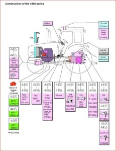
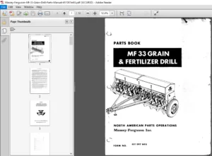
IMAGES PREVIEW OF THE MANUAL:
MASSEY FERGUSON 5400 SERIES TRACTORS SERVICE MANUAL – PDF DOWNLOAD:
PLEASE NOTE:
- This is not a physical manual but a digital manual – meaning no physical copy will be couriered to you. The manual can be yours in the next 2 mins as once you make the payment, you will be directed to the download page IMMEDIATELY.
- This is the same manual used by the dealers inorder to diagnose your vehicle of its faults.
- Require some other service manual or have any queries: please WRITE to us at [email protected]

Forest Hugh –
fine so far