
Massey Ferguson 9695 / 9795 Rotary Combine Electrical Workshop Service Manual – Section 10 (4283358M1)
Original price was: $39.95.$24.95Current price is: $24.95.
The complete electrical section of the Massey Ferguson 9695 / 9795 rotary combine workshop service manual, published under document number 4283358M1. Covers Console II diagnostics, VMM and mVEC modules, fuse and relay locations, machine grounds, sensor and switch testing, electromagnetic clutch troubleshooting, batteries, starting and charging systems, plus system-by-system wiring diagrams.
Description
The Massey Ferguson 9695 / 9795 Rotary Combine Electrical Workshop Service Manual – Section 10 (4283358M1) is the electrical volume of the workshop service manual for these two rotary combines, and it is where the machine’s wiring, control modules, sensors, alarms, grounds and starting and charging systems are documented in full. Rather than a handful of generic pages at the back of a repair book, this is a dedicated electrical section: general test procedures, the complete Console II terminal operating and diagnostic structure, component location photography, VMM and mVEC input/output tables, machine ground points, and dozens of wiring diagrams split by individual system. Anyone chasing a no-start, an unloader that will not swing, a chaffer that will not move, a grain tank cover that refuses to open, or a screen filling with alarms can work from the same drawings and diagnostic menus used in the workshop.
File Details
- Manual type: Workshop service manual – Section 10, Electrical
- Brand: Massey Ferguson
- Models covered: 9695 and 9795 rotary combines
- Document number: 4283358M1
- Language: English
- File format: PDF
- Page count: 202 pages
Chapters Covered
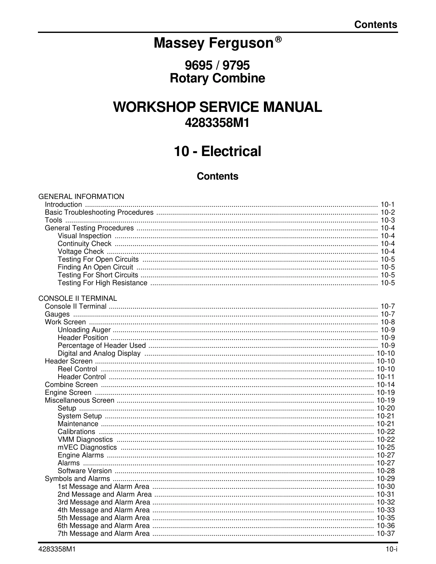
- General Information – introduction to the electrical system, basic troubleshooting procedures, tools, general testing procedures
- Visual Inspection, Continuity Check, Voltage Check, Testing for Open Circuits, Finding an Open Circuit
- Testing for Short Circuits, Testing for High Resistance, finding a high resistance circuit
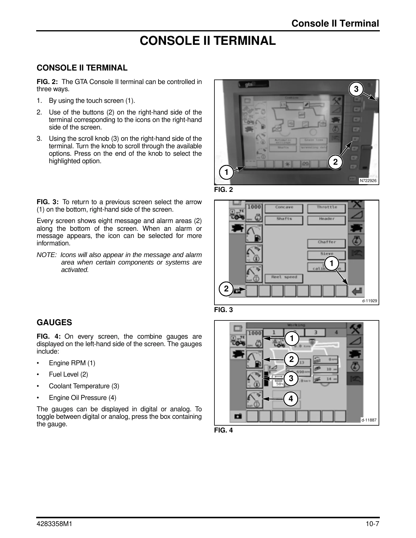
- Console II Terminal – gauges, work screen, unloading auger, header position, percentage of header used, digital and analog display
- Header Screen – reel control, header control, tilt, automatic header height control (AHHC), return to cut (RTC), float, table setting
- Combine Screen – temperature and moisture, grain tank, yield, rotor, feeder chain, concave, cleaning shoe, spreader, automatic settings, grain loss, shafts, harvesting data
- Engine Screen, Miscellaneous Screen, Setup, System Setup, Maintenance, Calibrations
- VMM Diagnostics, mVEC Diagnostics, Engine Alarms, Alarms, Software Version, Symbols and Alarms
- Message and alarm areas one through eight, Engine Diagnostics, Engine Trouble Code List
- Cab Electrical Component Locations – electronic modules, steering column, seat and console, right-hand seat mounted console, right-hand armrest switches, seat, park brake
- Overhead Console – lights and wiper switches, heating and air conditioning, electric mirrors, windshield wiper, radio, power outlets
- Chassis Sensor Location – adjusting switches, adjusting inductive sensors, sensors and switches and electrical components, miscellaneous electrical components
- Electrical Circuits – fuse and relay panel, relay locations, fuse location and amperage, fuses and relays outside of cab, primary circuit breaker
- MVEC Relay Boxes – location, relay and fuse location, VMM inputs and outputs for VMM1 through VMM6
- Testing – fuse testing, relay testing, diode test, machine grounds, cab frame grounds, under cab grounds, main machine and battery grounds
- Wiring Diagrams – general information, harness abbreviations, splice cross reference
- Electrical Troubleshooting – thresher, header and unloading electromagnetic clutch, seat interlock switch
- Electrical header and separator clutch troubleshooting, clutch removal and installation, clutch magnet and armature inspection, testing clutch magnet
- Clutch brush holder, continuity test, diode test, brush holder servicing and installation, bin unloading clutch circuit
- Batteries – safety precautions, general, battery connections, battery disconnect switch, starting engine with booster battery
- Starting System – general information, ignition switch, system operation, battery condition
- Charging System – introduction, troubleshooting charging systems, systems with voltmeter, no output, alternator bench test
Read together, these chapters give a technician a complete working picture of the 9695 and 9795 electrical architecture. The general testing section sets out how to use a volt-ohm meter on a machine that runs 12 volt, 8 volt and 5 volt circuits, and explains continuity, voltage, open circuit, short circuit and high resistance testing in the order you would actually perform them. From there the manual moves into how the machine reports its own faults: the Console II terminal pages for the work screen, header screen, combine screen, engine screen and miscellaneous screen, including the calibration menu, the VMM and mVEC diagnostic pages, and the alarm and message areas that flag everything from a blocked air filter to a rotor speed sensor failure. Component location coverage then shows where each module, switch, sensor, actuator and ground actually sits on the machine, which is the part that saves the most time on a machine you have not worked on before.
Wiring Diagrams Included
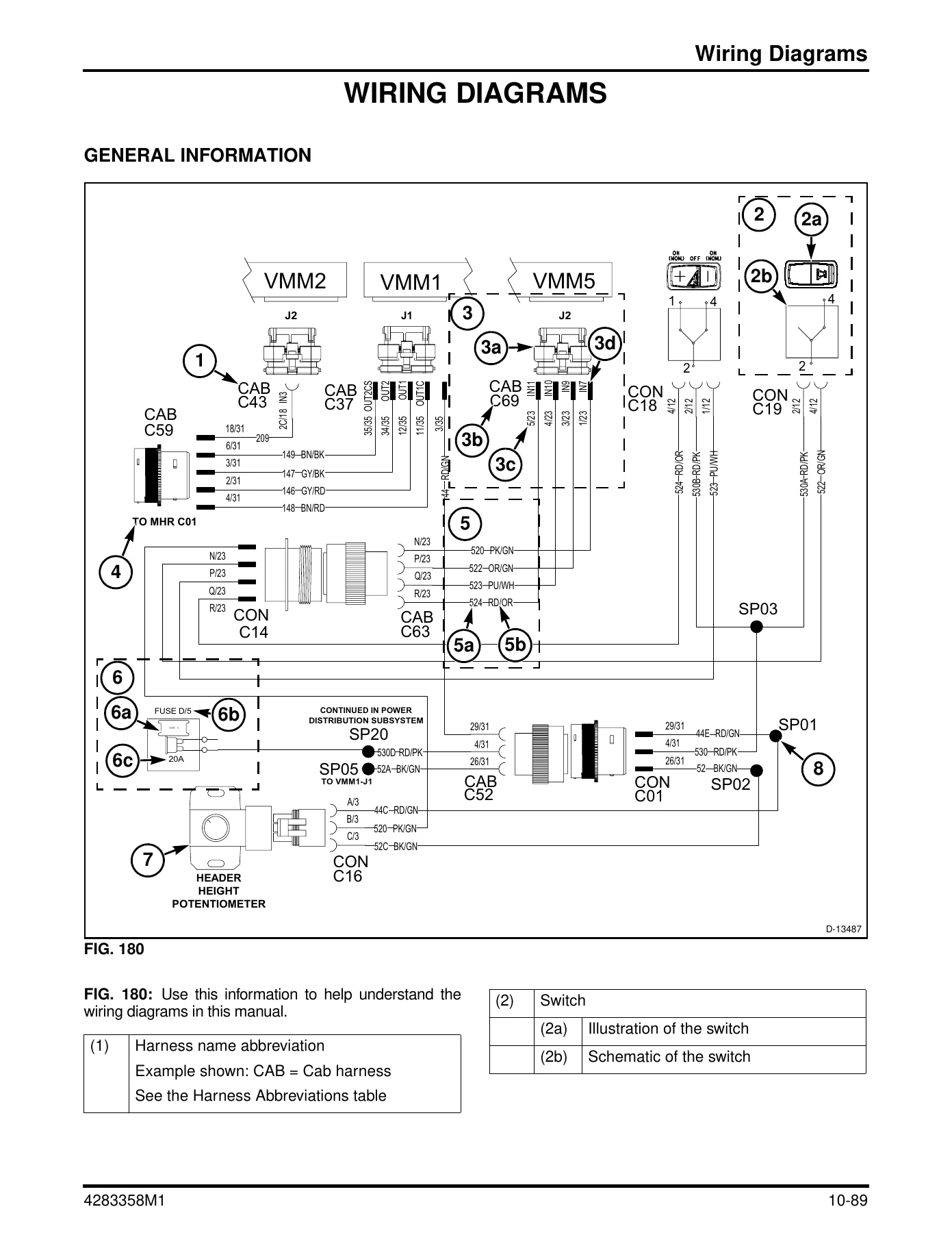
The diagram set is organised system by system, with a harness abbreviation table and a splice cross reference so you can trace a circuit across several drawings without losing it. Diagrams in this section include:
- Air conditioner and blower
- AutoGuide
- Beacon light
- Clutch and feeder reverse
- Concave and separator fan control
- Grain loss monitor (HUC6101 to HUC6999 and HUC7101 to HUC7999)
- Lighter and power receptacles
- Power ladder
- Rear work and service lights
- Rotor speed control
- Sieve and chaffer control
- Switch circuits and switch backlighting
- Unloading auger and swing
- Windshield wiper, seat switch and power mirrors
- Header height and tilt
- Rear wheel assist
- Reel position and reel speed
- Headlights
- Radio and horn
- Power distribution (three parts)
- Engine start and run
- Fieldstar and moisture sensor
- Sensor circuits and speed sensors
- Grain bin switch circuits
- Taillights, backup lights and alarm
- Unloader, exit and row finder lights
- Field lights
- Data bus and AutoGuide roof
- SMV and turn signals
- Vertical knife
Each diagram carries circuit numbers, wire colours, wire gauges and signal names, and the drawings are broken at harness connectors so a circuit can be followed from one page to the next. Fuse symbols match the decal on the machine, and connector illustrations show pin numbering and connector names, so a wire found in the cab can be matched to the same circuit out at the header or the rear of the machine.
Troubleshooting and Diagnostic Content
The troubleshooting chapters are written around symptoms rather than theory. The electromagnetic clutch chapter explains how the thresher, header and unloading clutches are powered, how the seat interlock delays and interrupts them, and then walks through magnet and armature inspection, voltage checks at the magnet terminals, field assembly continuity checks, current draw measurement and brush holder servicing including diode testing. Separate symptom tables cover the header and separator clutch failing to engage, failing to disengage, slipping, and the equivalent faults on the bin unloading clutch circuit.
Alarm and fault coverage is equally practical. The engine trouble code list identifies the codes broadcast by the engine controller, the colour of the engine RPM LED that accompanies each one, and the meaning of each code, from battery voltage low and high through throttle sensor defects, oil pressure faults, boost pressure faults, coolant and intake manifold temperature faults, and fuel filter pressure codes. Diagnostic trouble codes are displayed directly on the Console II terminal, so the code list works alongside the diagnostic screens rather than replacing them.
Why This Electrical Section Pays for Itself
Electrical faults on a rotary combine are rarely solved by guessing which wire is at fault. This Massey Ferguson 9695 / 9795 electrical workshop service manual gives you the voltage checks, resistance values, current draw figures, sensor air gaps, module input and output tables, alarm classes and wiring diagrams needed to test a circuit instead of replacing parts until something works. It supports real jobs on real machines: diagnosing a module that has gone offline, testing a potentiometer that will not change value, calibrating a concave, chaffer, sieve, header or reel speed, tracing a short between harness connectors, checking machine and cab frame grounds, or confirming whether a clutch magnet or a switch is the problem.
Correct procedures matter on a machine with this many interlinked electronic modules, because a misdiagnosed sensor or a poor ground can take a whole harvesting day out of the schedule. Having the wiring diagrams and the module pinout tables in front of you shortens that process considerably.
IMAGES PREVIEW
Delivery is instant. This is a downloadable PDF – there is no printed book to ship and nothing to wait for. After payment the file is available immediately, it can be opened on a laptop, tablet or phone in the workshop or out in the field, and any page can be printed for the bench or taped inside the cab while you work. The Massey Ferguson 9695 / 9795 rotary combine electrical section is a reference you will come back to every time an alarm appears on the Console II screen.
Reviews
There are no reviews yet.