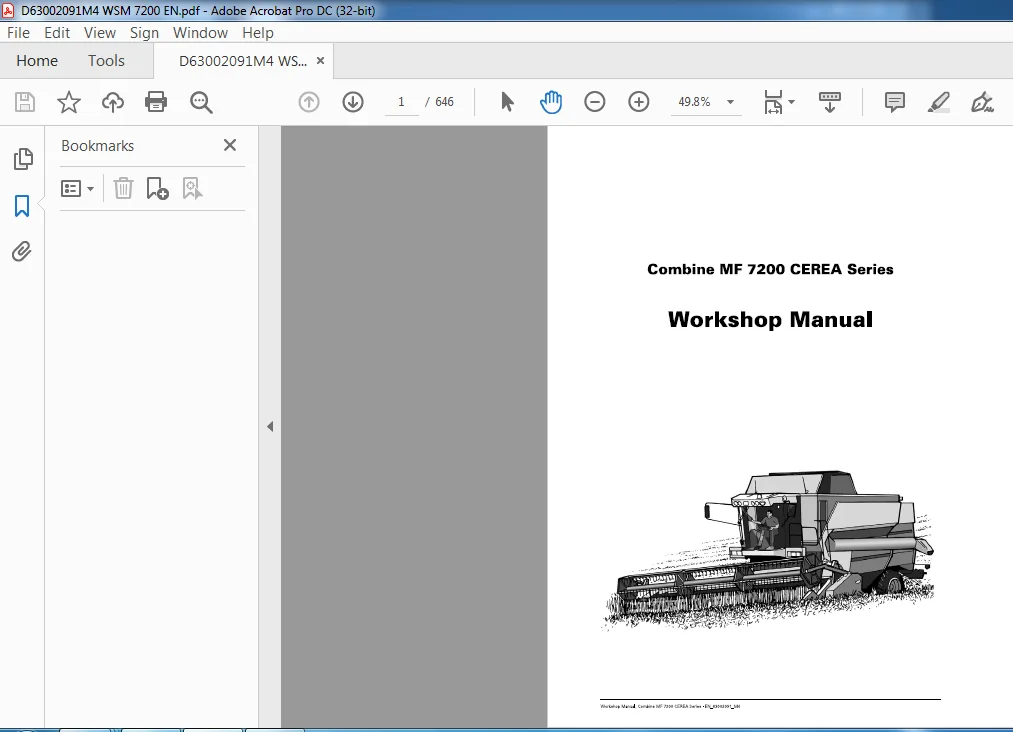
Massey Ferguson Combine MF7200 CEREA Series Workshop Manual – PDF DOWNLOAD
Original price was: $39.95.$23.95Current price is: $23.95.
Massey Ferguson Combine MF7200 CEREA Series Workshop Manual – PDF DOWNLOAD
Description
Massey Ferguson Combine MF7200 CEREA Series Workshop Manual – PDF DOWNLOAD
DESCRIPTION:
Massey Ferguson Combine MF7200 CEREA Series Workshop Manual – PDF DOWNLOAD
General :
The purpose of the manual is to help dealers and workshops start-up, service and repair AGCO’s equipment in the most appropriate and effective manner. If the specified procedures are followed and the recommended special tools are used where necessary, tasks and work can be completed within the time indicated in the manual ” Repair Time Schedule”.
Repairs and replacement of parts:
- When replacing parts, it is very impatant to only ever use genuine AGCO spares. Please pay particular attention to the folowing points with regard to repairs and fitting spare parts and other equipment. Fitting non-genuine spare parts may impair the safety of the machine. In some countries it is against the law to fit parts that do not conform to the manufacturer’s specifications.
- Torque wrenches must always be adjusted in accordance with the instructions given in the workshop manual. Fit locking devices where specified. If the locking device is ruined by removal, fit a new one. If non-genuine AGCO parts are fitted, the machine will no longer be covered by the right of complaint, as the manufacturer provides a warranty on all AGCO components. AGCO dealers are under the obligation to supply genuine parts only.
MASSEY FERGUSON COMBINE MF7200 CEREA SERIES WORKSHOP MANUAL – PDF DOWNLOAD:
IMAGES PREVIEW OF THE MANUAL:
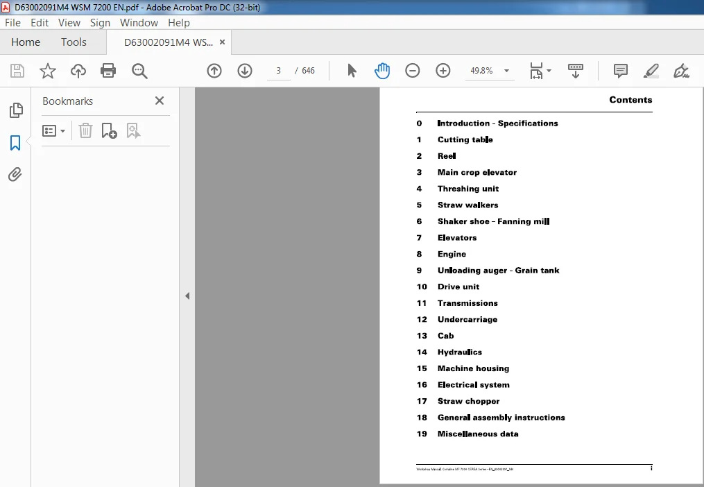
TABLE OF CONTENTS:
Massey Ferguson Combine MF7200 CEREA Series Workshop Manual – PDF DOWNLOAD
0 Introduction – Specifications
1 Cutting table
2 Reel
3 Main crop elevator
4 Threshing unit
5 Straw walkers
6 Shaker shoe – Fanning mill
7 Elevators
8 Engine
9 Unloading auger – Grain tank
10 Drive unit
11 Transmissions
12 Undercarriage
13 Cab
14 Hydraulics
15 Machine housing
16 Electrical system
17 Straw chopper
18 General assembly instructions
19 Miscellaneous data
0: Introduction – Specifications 1
0 1 Use of the manual 3
0 2 General specifications 4
0 3 Dimensions and weight 1 1
0 4 Safety precautions 1 3
0 4 1 Safety in the workshop 1 3
0 4 2 Safety – a word to the mechanic 1 3
0 4 3 Safety – danger, warning and caution 1 3
0 4 4 Safety decals 1 3
0 4 5 General 1 3
0 4 6 Personal safety 1 3
0 4 7 Considerations with regard to equipment 1 4
0 4 8 General considerations 1 4
0 4 9 Operational considerations 1 5
0 4 1 0 Maintenance techniques 1 6
0 5 Practical advice 1 7
0 6 Start-up instructions 2 1
0 6 1 General 21
0 6 2 Pre-delivery checks 2 1
0 6 3 Instruction of combine operator 2 2
0 7 Conversion tables 2 5
0 7 1 Conventional Units of Measurement 25
0 8 Locking and sealing agents 2 7
0 9 Torques 2 8
0 9 1 Wheels 28
0 9 2 Screws with metric threads 29
0 9 3 Nuts with metric threads 3 0
1 : Cutting table 31
1 1 General 33
1 2 Knife drive – wobble box 35
1 2 1 Removal 3 5
1 2 2 Mounting 36
1 2 3 Reconditioning the wobble box 3 8
1 2 4 Fitting knife clips and crop lifters 4 2
1 3 Table auger 43
1 3 1 Removal 4 3
1 3 2 Mounting 4 3
1 3 3 Replacement of shaft on the right-hand side 4 4
1 3 4 Replacement of shaft on the left-hand side 4 5
1 3 5 Replacement of crankshaft 4 5
1 3 6 Replacement of feathering fingers, bearings and bushes 46
1 3 7 Adjustment of table auger and feathering fingers 4 7
1 4 Table body 4 8
1 4 1 Adjustment of cut-off strips 4 8
1 4 2 Adjustment and positioning of ground sensor – PowerFlow 4 9
1 4 3 Adjustment and positioning of ground sensor – FreeFlow 5 1
1 5 Slip clutch and chain drive 52
1 5 1 Removal 5 2
1 5 2 Mounting 5 2
1 5 3 Replacement of bearings and sprockets 5 3
1 6 Countershaft 5 4
1 6 1 Removal 5 5
1 6 2 Mounting 56
1 7 PowerFlow table 5 7
1 7 1 Removal, belts 58
1 7 2 Mounting, belts 60
1 7 3 Replacement of front rollers and bearings, scraper adjustment 6 2
Workshop Manual, Combine M F 7200 CEREA Series – EN_63002091_M4 iii
Contents
1 7 4 Replacement of rear rollers and bearings, scraper adjustment 6 4
1 7 5 Replacement and alignment of bearing housing, rear rollers 6 4
1 7 6 Belt tensioning and running-in 66
2: Reel 69
2 1 Reel 7 1
2 1 1 Removal 7 1
2 1 2 Mounting 7 2
2 1 3 Replacement of reel tine bar and plastic bearings 7 3
2 1 4 Replacement of guide rollers, eccentric, guide ring and bearings 7 4
2 1 5 Replacement of reel plates 7 5
2 1 6 Replacement o f reel tube, bearings 7 5
2 2 Oil motor and chain drive 7 6
2 2 1 Replacement of oil motor 7 6
2 3 Hydraulic cylinders 7 7
2 3 1 Replacement of cylinder – reel up/down 7 7
2 3 2 Replacement of cylinder – reel forward/back 7 8
2 3 3 Reconditioning of hydraulic cylinders 7 8
3: Main crop elevator 83
3 1 General 85
3 2 Main crop elevator 86
3 2 1 Removal 86
3 2 2 Mounting 8 7
3 2 3 Bearing block on machine frame 88
3 2 4 Replacement of lifting ram 88
3 2 5 Reconditioning of hydraulic cylinder 89
3 2 6 Replacement of cutting height preset sensor 90
3 3 Elevator chain 9 1
3 3 1 Removal 91
3 3 2 Mounting 91
3 3 3 Replacement of slats 9 2
3 3 4 Replacement of slide rails in crop elevator 9 2
3 3 5 Replacement of intermediate plate 9 2
3 4 Elevator chain top shaft 9 3
3 4 1 Removal 9 3
3 4 2 Mounting 9 3
3 4 3 Replacement of bearings 9 4
3 4 4 Replacement of sprockets 9 5
3 4 5 Replacement of shaft protection tube 96
3 5 Elevator chain front shaft 9 7
3 5 1 Removal 9 7
3 5 2 Mounting 9 7
3 5 3 Replacement of shaft, bearings and plate wheels 98
3 6 Elevator countershaft 9 9
3 6 1 Removal 9 9
3 6 2 Mounting 1 00
3 6 3 Replacement of bearings and sprockets 1 00
3 7 Table clutch and chain drive 101
3 7 1 Removal 1 01
3 7 2 Mounting 1 01
3 7 3 Reconditioning of clutch 1 01
3 8 Adapter 102
3 8 1 Removal 1 0 2
3 8 2 Mounting 1 0 3
3 8 3 Replacement of cylinder/connecting rod 1 0 3
3 8 4 Reconditioning of hydraulic cylinder 1 0 4
3 8 5 Replacement of angle sensor 1 0 5
3 9 Hydraulic reversing 106
iV Workshop Manual Combine MF 7200 CEREA Series – EN_63002091_M4
Contents
3 9 1 Removal 1 06
3 9 2 Mounting 1 06
3 10 Electrical Reversing 107
3 1 0 1 Removal 1 0 7
3 1 0 2 Mounting 1 0 7
4: Threshing unit 109
4 1 General 111
4 2 Stone trap 112
4 2 1 Removal 1 1 2
4 2 2 Mounting 1 1 2
4 3 Concave 113
4 3 1 Removal 1 1 3
4 3 2 Mounting 1 1 3
4 3 3 Lateral adjustment of the concave 1 1 4
4 3 4 Concave setting – initial setting 1 1 4
4 3 5 Replacement of lead-in plate 1 1 5
4 3 6 Replacement of concave extension 1 1 5
4 3 7 Replacement of shaft for concave setting 1 1 6
4 4 Threshing cylinder 117
4 4 1 Removal 1 1 7
4 4 2 Mounting 1 1 8
4 4 3 Replacement of bearings 1 1 9
4 4 4 Replacement of rasp bars and backing bars 1 20
4 4 5 Replacement of shaft and cylinder spiders 1 20
4 5 Cylinder variator – table clutch 12 1
4 5 1 Removal, hydraulic variator 1 21
4 5 2 Mounting, hydraulic variator 1 21
4 5 3 Reconditioning of hydraulic variator pulley 1 22
4 5 4 Removal, mechanical variator 1 24
4 5 5 Mounting, mechanical variator 1 24
4 5 6 Reconditioning of mechanical variator pulley 1 2 5
4 5 7 Removal, magnetic clutch 1 26
4 5 8 Mounting, magnetic clutch 1 27
4 5 9 Reconditioning of magnetic clutch 1 28
4 6 Bracket for counter drive 1 30
4 6 1 Removal 1 30
4 6 2 Mounting and alignment 1 30
4 7 Rear beater 1 31
4 7 1 Removal 1 3 1
4 7 2 Mounting 1 3 2
4 7 3 Replacement of bearings 1 3 3
4 8 Rear beater concave 134
4 8 1 Removal 1 3 4
4 8 2 Mounting 1 3 4
4 9 Rotary separator cylinder 1 3 5
4 9 1 Removal 1 3 5
4 9 2 Mounting 1 36
4 9 3 Replacement of bearings 1 3 7
4 9 4 Replacement of rasp bars 1 3 7
4 10 Rotary separator concave 1 3 8
4 1 0 1 Removal 1 3 8
4 1 0 2 Mounting 1 3 9
4 1 0 3 Concave setting – initial setting 1 3 9
4 1 0 4 Replacement of shaft for concave setting 1 40
5: Straw walkers 141
5 1 General 1 4 3
5 2 Straw walkers 1 4 4
Workshop Manual, Combine MF 7200 CEREA Series – EN_63002091_M4 V
Contents
5 2 1 Removal 144
5 2 2 Mounting 144
5 3 Crank – front 1 4 5
5 3 1 Removal 145
5 3 2 Mounting 146
5 3 3 Replacement of bearings 146
5 4 Crank – rear 1 4 7
5 4 1 Removal 147
5 4 2 Mounting 147
5 4 3 Replacement of bearings 147
5 5 Straw walker transmission – chain 1 4 8
5 5 1 Removal 148
5 5 2 Mounting 148
6: Shaker shoe – Fanning mill 149
6 1 General 1 5 1
6 2 Fanning mill 1 52
6 2 1 Removal 15 2
6 2 2 Mounting 15 3
6 2 3 Replacement of fan blades 15 4
6 2 4 Replacement of fanning mill deflectors 15 4
6 2 5 Replacement of seals 15 5
6 3 Main grain pan 1 5 6
6 3 1 Removal 15 6
6 3 2 Mounting 15 7
6 3 3 Replacement of swivel arm and bearings 15 7
6 3 4 Replacement of seals 15 8
6 4 Second grain pan 1 5 9
6 4 1 Removal 159
6 4 2 Mounting 159
6 4 3 Replacement of swivel arm and bearings 16 0
6 4 4 Adjustment of second grain pan 16 1
6 5 Top shaker shoe 16 3
6 5 1 Removal 16 3
6 5 2 Mounting 16 4
6 5 3 Replacement of swivel arm and bearings 16 5
6 5 4 Replacement of seals 16 5
6 5 5 Electric sieve setting – initial setting 16 6
6 6 Bottom shaker shoe 16 7
6 6 1 Removal 16 7
6 6 2 Mounting 16 8
6 6 3 Replacement of swivel arm and bearings 16 8
6 6 4 Replacement of seals 169
6 6 5 Electric sieve setting – initial setting 169
6 7 Bottom augers 170
6 7 1 Removal 170
6 7 2 Mounting 170
6 8 Eccentric drive 1 7 1
6 8 1 Removal 171
6 8 2 Mounting 172
6 8 3 Adjustment of connecting rod/ alignment of shaker shoes 173
6 8 4 Replacement of connecting rod bearing 174
6 8 5 Replacement of bearings and eccentric shaft 175
6 9 Transmissions 1 7 6
6 9 1 Replacement and reconditioning of fanning mill variator 176
6 9 2 Adjustment of fanning mill variator 177
6 9 3 Replacement and reconditioning of counter drive, shaker shoe 178
yj Workshop Manual Combine MF 7200 CEREA Series – EN_63002091_M4
Contents
7: Elevators 179
7 1 Tank filling elevator 1 8 1
7 1 1 Removal 1 81
7 1 2 Mounting 1 82
7 1 3 Replacement of top shaft, bearings and sprockets 1 82
7 1 4 Replacement of bottom sprocket 1 8 3
7 1 5 Replacement of elevator chain 1 8 3
7 1 6 Moisture sensor 1 8 4
7 1 7 Yieldmeter sensor 1 8 4
7 2 Returns elevator 1 8 5
7 2 1 Removal 1 8 5
7 2 2 Mounting 1 8 5
7 2 3 Replacement of top shaft, bearings and sprockets 1 86
7 2 4 Replacement of bottom sprocket 1 86
7 2 5 Replacement of elevator chain 1 86
7 2 6 Returns volume sensor 1 86
7 3 Returns thresher 1 8 7
7 3 1 Removal 1 8 7
7 3 2 Mounting 1 8 7
7 3 3 Replacement of sprockets 1 8 7
7 3 4 Replacement of threshing cylinder 1 8 7
7 3 5 Reconditioning of right-angle gear 1 88
7 4 Tank filling auger 190
7 4 1 Removal 1 90
7 4 2 Mounting 1 90
7 4 3 Replacement of top bearing 1 90
7 4 4 Reconditioning of right-angle gear 1 91
7 5 Transmission 1 92
7 5 1 Replacement of shaft, bearings and sprockets 1 92
8: Engine 193
8 1 General 1 9 5
8 2 Replacement of engine 196
8 2 1 Removal of engine assembly 1 96
8 2 2 Mounting of engine assembly 1 99
9: Unloading auger – Grain tank 201
9 1 Unloading auger 2 0 3
9 1 1 Removal 20 3
9 1 2 Mounting 20 3
9 1 3 Replacement of bearings and universal joints 20 4
9 2 Unloading tube 2 0 5
9 2 1 Removal 20 5
9 2 2 Mounting 20 5
9 2 3 Replacement of swivel bearing 206
9 2 4 Replacement of hydraulic cylinder 20 7
9 2 5 Reconditioning of hydraulic cylinder 208
9 3 Bottom auger and cover plate 2 0 9
9 3 1 Removal 209
9 3 2 Mounting 209
9 3 3 Replacement of bearings, safety clutch 2 1 0
9 4 Transmission 2 11
9 4 1 Replacement of unloading auger shaft, bearings 2 1 1
9 4 2 Replacement and reconditioning of magnetic clutch 2 1 1
9 5 Grain tank covers 2 1 3
9 5 1 Removal 2 1 3
9 5 2 Mounting 2 1 3
Workshop Manual, Combine MF 7200 CEREA Series – EN_63002091_M4 vii
Contents
1 0: Drive unit 21 5
10 1 Radiator – lntercooler 2 17
1 0 1 1 Removal 21 7
1 0 1 2 Mounting 21 7
10 2 Oil cooler 2 1 8
1 0 2 1 Removal 21 8
1 0 2 2 Mounting 21 8
10 3 Condenser – air-conditioning 2 19
1 0 3 1 Removal 21 9
1 0 3 2 Mounting 21 9
10 4 Rotary screen 22 0
1 0 4 1 Removal 2 20
1 0 4 2 Mounting 2 21
1 0 4 3 Adjustment of rotary screen and cleaning blade 222
1 0 4 4 Replacement of drive shaft and clutch 2 2 3
10 5 Dust aspirator 22 6
1 0 5 1 Removal 2 26
1 0 5 2 Mounting 2 26
10 6 Hydrostatic pump 22 7
1 0 6 1 Removal 2 27
1 0 6 2 Mounting 2 28
1 0 6 3 Tensioning device 2 29
10 7 Auxiliary hydraulic pump 2 30
1 0 7 1 Removal 2 3 0
1 0 7 2 Mounting 2 3 0
10 8 Hydraulic oil tank 2 31
1 0 8 1 Removal 2 3 1
1 0 8 2 Mounting 2 3 1
10 9 Fuel tank 2 32
1 0 9 1 Removal 2 3 2
1 0 9 2 Mounting 2 3 2
1 0 9 3 Tank gauge 2 3 2
10 10 Compressor – air-conditioning 2 34
1 0 1 0 1 Removal 2 3 4
1 0 1 0 2 Mounting 2 3 4
10 11 Power take-off 2 35
1 0 1 1 1 Removal 2 3 5
1 0 1 1 2 Mounting 2 3 6
1 0 1 1 3 Replacement o f clutch disc 2 37
1 0 1 1 4 Replacement of output shaft, bearing and hub 2 3 8
1 1 : Transmissions 239
11 1 General 2 41
11 2 Countershaft 2 42
1 1 2 1 Removal 2 4 2
1 1 2 2 Mounting 2 4 3
1 1 2 3 Replacement of bearings 2 4 4
1 1 2 4 Reconditioning of safety clutch 2 4 4
11 3 Replacement of belts, right-hand side 2 4 5
1 1 3 1 Rear beater – counter drive, cylinder variator 24 5
1 1 3 2 Counter drive, variator – threshing cylinder 246
1 1 3 3 Rear beater – rotary separator 2 47
1 1 3 4 Fanning mill – fanning mill variator 2 47
1 1 3 5 Rear beater – fanning mill variator 2 4 8
1 1 3 6 Unloading auger shaft – unloading auger 2 4 9
1 1 3 7 Unloading auger shaft – rotary screen clutch 2 50
1 1 3 8 Unloading auger shaft – dust aspirator 2 51
1 1 3 9 Countershaft – counter drive, elevators 2 5 2
11 4 Replacement of chains, right-hand side 2 5 3
Viii Workshop Manual Combine MF 7200 CEREA Series – EN_63002091_M4
Contents
1 1 4 1 Counter drive, elevators – returns elevator 2 5 3
1 1 4 2 Counter drive, elevators – tank filling elevator 2 5 3
1 1 4 3 Counter drive, elevators – tank filling auger 2 5 3
1 1 4 4 Returns elevator – returns thresher 2 5 4
1 1 4 5 Reel drive 2 5 4
1 1 4 6 Elevator chain top shaft – electrical reversing 2 5 5
11 5 Replacement of belts, left-hand side 2 5 6
1 1 5 1 Countershaft – straw walker drive 2 56
1 1 5 2 Countershaft – rear beater 2 56
1 1 5 3 Countershaft – counter drive, straw chopper 2 5 7
1 1 5 4 Counter drive – straw chopper 2 5 7
1 1 5 5 Engine – countershaft 2 58
1 1 5 6 Rear beater – countershaft, shaker shoe drive 2 5 9
1 1 5 7 Countershaft, shaker shoe drive – eccentric shaft 260
1 1 5 8 Countershaft, shaker shoe drive – straw walker crank 260
1 1 5 9 Rear beater – elevator chain top shaft 26 1
1 1 5 1 0 Engine – unloading auger shaft 26 1
1 1 5 1 1 Engine – hydrostatic pump 262
1 1 5 1 2 Table countershaft – knife drive 26 3
1 1 5 1 3 Countershaft – hydraulic pump, chaff spreader 26 3
11 6 Replacement of chains, left-hand side 2 6 4
1 1 6 1 Table countershaft – table auger 26 4
1 1 6 2 Elevator chain top shaft – elevator countershaft 26 4
1 1 6 3 Table auger – belt rollers (PowerFlow) 26 5
1 1 6 4 Straw walker drive 26 5
1 1 6 5 Hydraulic motor, reversing – elevator countershaft 266
12: Undercarriage 267
12 1 Auto Level final drive bracket – 4 speeds 2 6 9
1 2 1 1 Removal 26 9
1 2 1 2 Mounting 2 70
1 2 1 3 Replacement of bushing 2 7 2
1 2 1 4 Replacement of hydraulic cylinder 2 7 3
1 2 1 5 Reconditioning of hydraulic cylinder 2 7 4
12 2 Final drive – 3 gear ranges 2 7 5
1 2 2 1 Removal 2 7 5
1 2 2 2 Mounting 2 7 5
1 2 2 3 Reconditioning of final drives 2 7 7
12 3 Gearbox – 4 gear ranges 2 80
1 2 3 1 Removal 2 80
1 2 3 2 Mounting 2 81
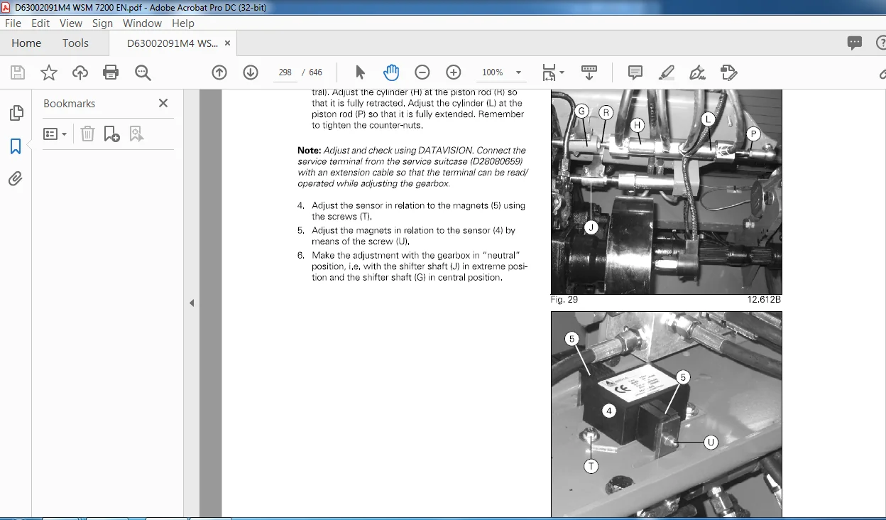
1 2 3 3 Adjustment of shifter cylinders and sensor 2 82
1 2 3 4 Adjustment of shifter cylinders and sensor 2 8 3
1 2 3 5 Replacement of lubrication pump 2 8 7
1 2 3 6 Replacement of shifter forks 2 88
1 2 3 7 Reconditioning of differential 289
1 2 3 8 Reconditioning of gearbox 2 9 3
12 4 Auto Level final drive bracket – 3 gear ranges 2 96
12 5 Final drive – 3 gear ranges 2 9 7
12 6 Gearbox – 3 gear ranges 2 9 8
1 2 6 1 Removal 2 98
1 2 6 2 Mounting 2 98
1 2 6 3 Replacement and adjustment of shifter cables 2 9 9
1 2 6 4 Replacement of shifter forks 3 00
1 2 6 5 Reconditioning of differential 3 00
1 2 6 6 Reconditioning of gearbox 3 00
12 7 Hydrostatic motor 301
1 2 7 1 Removal 301
1 2 7 2 Mounting 301
12 8 Brakes, machines with 4 gear ranges 302
Workshop Manual, Combine MF 7200 CEREA Series – EN_63002091_M4 ix
Contents
1 2 8 1 Replacement of brake blocks 302
1 2 8 2 Replacement of brake discs 30 3
1 2 8 3 Replacement of handbrake shoes 3 0 5
1 2 8 4 Bleeding of the brakes 30 5
12 9 Rear axle 307
General 3 0 7
Removal 3 0 7
Mounting 3 0 7
Replacement of king pins and bushings 308
Replacement of steering cylinder 309
Reconditioning of hydraulic cylinder 309
Adjustment of toe-in and steering deflection 3 1 0
13: Cab 313
1 3 1 Pedals and levers 31 5
1 3 1 1 Gear lever 3 1 5
1 3 1 2 Multi-function lever 3 1 6
1 3 1 3 Throttle lever and cable 3 1 8
1 3 1 4 Brake pedals and main cylinder 3 20
1 3 1 5 Handbrake lever and cable 3 2 3
1 3 2 Control panel, right-hand side 32 4
1 3 3 Replacement of windscreen 32 5
1 3 4 Control panel in roof 32 6
1 3 5 Roof 32 7
Outer roof 3 2 7
I nspection doors 3 27
Replacement of windscreen wiper 3 2 8
Replacement o f blower 3 2 8
Replacement o f heating element 3 2 9
Replacement of evaporator 3 2 9
14: Hydraulics 331
1 4 1 General 333
1 4 1 1 Emptying and filling the hydrostatic system 3 3 4
1 4 1 2 Running-in and bleeding the hydrostatic system 3 36
1 4 1 3 Running-in and bleeding of auxiliary hydraulics 3 36
1 4 2 Hydrostatic system 339
1 4 2 1 Hydraulic pump 3 3 9
1 4 2 2 Oil motor 3 3 9
1 4 2 3 Oil cooler 3 3 9
1 4 2 4 Hydraulic oil filter 3 4 1
1 4 3 Auxiliary hydraulics 343
1 4 3 1 Hydraulic pump 3 4 3
1 4 3 2 Hydraulic oil tank and return oil filter 3 4 3
1 4 3 3 Oil cooler 3 4 3
1 4 3 4 Hydraulic valve – main valve 3 4 5
1 4 4 Table 347
1 4 4 1 Hydraulic cylinders – table up/down 3 4 7
1 4 4 2 Pressure accumulators – cutting table 3 4 7
1 4 4 3 Hydraulic valve – table up/down (standard machine) 3 4 7
1 4 4 4 Hydraulic valve – table up/down (Auto Level machine) 3 4 9
1 4 4 5 Hydraulic cylinder – table levelling 3 5 1
1 4 4 6 Pressure accumulators – levelling 3 5 1
1 4 4 7 Hydraulic valve – levelling 3 5 1
1 4 5 Auto Level 35 3
1 4 5 1 Hydraulic cylinders – machine levelling 3 5 3
1 4 5 2 Hydraulic valve – machine up/down/levelling 3 5 5
1 4 6 Reel 3 5 7
1 4 6 1 Hydraulic cylinders – reel up/down 3 5 7
X Workshop Manual Combine MF 7200 CEREA Series – EN_63002091_M4
Contents
1 4 6 2 Hydraulic valve – reel up/down 3 5 7
1 4 6 3 Hydraulic cylinders – reel fore/aft 3 5 9
1 4 6 4 Hydraulic valve – reel fore/aft 3 5 9
1 4 6 5 Oil motor 3 6 1
1 4 6 6 Flowdivider 3 6 1
1 4 7 Gearshift 36 3
1 4 7 1 Hydraulic cylinders – gearshift 36 3
1 4 7 2 Hydraulic valves – gearshift 3 6 3
1 4 8 Steering 36 5
1 4 8 1 Hydraulic cylinders – steering 36 5
1 4 8 2 Orbitrol steering valve 3 6 5
1 4 9 Cylinder variator 36 7
1 4 9 1 Cylinder variator 36 7
1 4 9 2 Hydraulic valve – variator 36 7
1 4 10 Unloading auger 36 9
1 4 1 0 1 Hydraulic cylinder – unloading auger 3 6 9
1 4 1 0 2 Hydraulic valve – unloading auger 3 6 9
1 4 11 Reversing 37 1
1 4 1 1 1 Oil motor 3 7 1
1 4 1 1 2 Hydraulic valve – reversing 3 7 1
15: Machine housing 373
1 5 1 General 37 5
16: Electrical system 377
16 1 General 37 9
16 2 Description of DATAV I S I O N 380
16 3 Electric box 3 8 1
1 6 3 1 Removal 3 81
1 6 3 2 Mounting 3 8 1
1 6 3 3 Replacement of computer 3 81
1 6 3 4 Replacement of relay base, busbar 3 81
16 4 Key to symbols 382
16 5 Diagrams – components 38 4
1 6 5 1 Ignition, diagram 1 0- 2 3 8 5
1 6 5 2 Start/stop, diagram 20-0 3 8 7
1 6 5 3 SISU engine, 7 4 ETA, EEM, diagram 2 5- 1 3 9 5
1 6 5 4 S ISU engine, Citius 8 4 CTA- 4V, EEM, diagram 2 5-2 3 9 9
1 6 5 5 Electric transmission, diagram 30- 3 40 3
1 6 5 6 Electric transmission, diagram 30- 4 40 7
1 6 5 7 Power, diagram 40-0 4 1 1
1 6 5 8 CAN, diagram 50-0 4 1 3
1 6 5 9 Terminal, diagram 60- 3 4 1 5
1 6 5 1 0 GPS/Com-Unit, diagram 70-2 4 1 9
1 6 5 1 1 Main light flash, diagram 80-0 4 2 1
1 6 5 1 2 Parking light, diagram 90-0 4 2 7
1 6 5 1 3 Stoplight, diagram 1 1 0-0 4 3 1
1 6 5 1 4 Work light, rear, diagram 1 20-0 4 3 5
1 6 5 1 5 Direction flashers, diagram 1 30- 1 4 3 9
1 6 5 1 6 Work light, roof, diagram 1 50-0 4 4 7
1 6 5 1 7 Work light, side, diagram 1 60-0 4 5 1
1 6 5 1 8 Cab light, diagram 1 70-0 4 5 5
1 6 5 1 9 External con nectors, diagram 200-0 4 5 7
1 6 5 20 Table trailer, diagram 2 1 0- 1 46 1
1 6 5 2 1 Blower/air-conditioning, diagram 2 2 0-0 46 5
1 6 5 2 2 Wiper, diagram 2 30-0 46 9
1 6 5 2 3 Lighter/seat adjustment, diagram 2 40-0 4 7 1
1 6 5 2 4 Radio, diagram 2 50-2 4 7 3
1 6 5 2 5 Horn, diagram 260-0 4 7 5
Workshop Manual, Combine MF 7200 CEREA Series – EN_63002091_M4 xi
Contents
1 6 5 26 Electrical concave setting, diagram 2 70- 1 4 7 7
1 6 5 2 7 Electrical gearshift diagram 2 80- 3 481
1 6 5 2 8 Full warning/rotating yellow beacon, diagram 300- 1 4 8 3
1 6 5 2 9 Table attachment diagram 3 1 0- 1 4 8 7
1 6 5 30 Table WWH U, attachment, diagram 3 1 0-2 4 9 1
1 6 5 3 1 Reversing, diagram 3 20-0 4 9 5
1 6 5 3 2 Bottom cover/grain tank cover, diagram 3 30-0 4 9 9
1 6 5 3 3 Unloading auger, diagram 3 40-0 50 3
1 6 5 3 4 Table up/down, diagram 3 50-2 50 7
1 6 5 3 5 Table up/down, diagram 3 50- 3 5 1 1
1 6 5 36 Variator, reel, fanning mill, diagram 360-0 5 1 5
1 6 5 3 7 Reel, diagram 3 70-0 5 1 9
1 6 5 3 8 Indicators, yield, loss, diagram 3 80-2 5 2 1
1 6 5 3 9 Vertical knives, diagram 400-0 52 5
1 6 5 40 Vertical knives, diagram 400- 1 52 7
1 6 5 4 1 Electrical sieves, diagram 4 1 0-0 52 9
1 6 5 42 Electrical straw deflectors, straw chopper, diagram 420-0 5 3 1
1 6 5 4 3 Four-wheel drive, diagram 4 30-0 5 3 3
1 6 5 4 4 Revolution sensors, diagram 5 1 0- 1 5 3 5
1 6 5 4 5 Sensors, diagram 520-0 5 4 5
1 6 5 46 Sensors, diagram 5 30-2 5 4 9
1 6 5 4 7 Tilt sensor, diagram 5 40-0 5 5 3
1 6 5 4 8 Auto Level table, diagram 5 50-0- 1 5 5 5
1 6 5 4 9 Auto Level table WWHU, diagram 5 50- 1 56 1
1 6 5 50 Auto Level machine, diagram 560-0 56 5
1 6 5 5 1 Maize header, diagram 5 9 5-0 56 9
1 6 5 52 Main switch, diagram 900-0 5 7 1
1 7: Straw chopper 573
17 1 General 5 7 5
1 8: General assembly instructions 577
1 8 1 Mounting of gib-head keys 5 7 9
1 8 2 Mounting of tightening pins 5 80
1 8 3 Mounting of hydraulic pipes and screw connections 5 8 1
1 8 4 Mounting of flanged bearing with locking collar 5 8 3
1 8 5 Mounting of sliding bushings 5 8 4
1 8 6 Removal of revolution sensor 5 8 5
1 8 7 Mounting of tightening rings 5 86
1 9: Miscellaneous data 587
1 9 1 General 5 8 9
1 9 2 Speeds – adjustment values 5 90
1 9 3 Maintenance 5 9 3
1 9 3 1 Lubrication Chart 59 3
1 9 3 2 Lubrication points, left-hand machine side 600
1 9 3 3 Lubrication points, right-hand machine side 6 1 4
1 9 3 4 Recommended lubricants 6 2 8
1 9? 5 Gear 6 2 9
1 9 3 6 Air-conditioning 6 3 1
PLEASE NOTE:
- This is the same manual used by the dealers to diagnose and troubleshoot your vehicle
- You will be directed to the download page as soon as the purchase is completed. The whole payment and downloading process will take anywhere between 2-5 minutes
- Need any other service / repair / parts manual, please feel free to contact [email protected] . We still have 50,000 manuals unlisted
S.V

Salem Gerald –
Good experience
Tomas Yusuf –
The information gave me the direction I needed to move forward with my repair Thx