Massey Ferguson EU Hay Equipment 1393 1395 Rotary Disc Mower Service Manual – PDF DOWNLOAD
Original price was: $65.95.$31.95Current price is: $31.95.
Massey Ferguson EU Hay Equipment 1393 1395 Rotary Disc Mower Service Manual – PDF DOWNLOAD
Description
Massey Ferguson EU Hay Equipment 1393 1395 Rotary Disc Mower Service Manual – PDF DOWNLOAD
DESCRIPTION:
Massey Ferguson EU Hay Equipment 1393 1395 Rotary Disc Mower Service Manual – PDF DOWNLOAD
General information
Introduction to this service manual
This service manual gives information from engineering tests, operating data, and the latest service techniques at the time of publication. Read this service manual carefully before doing any service on the machine. The photos and illustrations used in this service manual were current at the time of publication. Production changes can cause machines to vary from the photos and the illustrations. The manufacturer reserves the right to redesign and change machines as necessary without notification.
Units of measurement
Measurements are given in metric units followed by the equivalent in U S units. Hardware sizes are given in millimeters for metric hardware and inches for U S hardware.
Table of contents
This manual has a table of contents at the front. The table of contents shows the divisions. The individual divisions also have a table of contents.
Page numbers
All pages have two numbers, such as 01-25. The first number shows the divis ion. The second number shows the page in the division. Page numbers occur on the lower right-hand or lower left-hand corner of each page.
TABLE OF CONTENTS:
Massey Ferguson EU Hay Equipment 1393 1395 Rotary Disc Mower Service Manual – PDF DOWNLOAD
1 General 1-1
1 1 General information 1-3
1 1 1 Introduction to this service manual 1-3
1 1 2 Units of measurement 1-3
1 1 3 Conversion table 1-4
1 1 4 Table of contents 1-5
1 1 5 Page numbers 1-5
1 1 6 lntended use 1-5
1 1 7 Proper disposai of waste 1-5
1 1 8 Weld on the machine precautions 1-5
1 2 Safety 1-6
1 2 1 Introduction 1-6
1 2 1 1 Safety symbol 1-6
1 2 1 2 Safety messages 1-6
1 2 1 3 Information messages 1-6
1 2 1 4 Safety signs 1-6
1 2 1 5 A word to the technician 1-7
1 2 1 6 T he service manual 1-8
1 2 2 Operation 1-8
1 2 2 1 Prepare for operation 1-8
1 2 2 2 General information 1-8
1 2 2 3 Persona! protective equipment 1-9
1 2 2 4 Seat instructions 1-10
1 2 2 5 Shield and guards 1-10
1 2 2 6 Power take-off safety 1-1 1
1 2 2 7 Exhaust warning 1-1 1
1 2 2 8 Flying debris 1-1 2
1 2 2 9 Agricultural chemicals 1-1 2
1 2 2 10 Travel on public roads 1-1 2
1 2 3 Maintenance 1-1 3
1 2 3 1 General maintenance information 1-1 3
1 2 3 2 Fire prevention and first aid 1-1 5
1 2 3 3 High pressure leaks 1-1 6
1 2 3 4 Accumulator safety 1-1 7
1 2 3 5 T ire safety 1-1 7
1 2 3 6 Replacement parts 1-1 8
1 3 Cylinder lockout valves 1-19
1 3 1 Lift cylinder lockout valves 1-1 9
1 3 1 1 Engage the lift cylinder lockout valves 1-1 9
1 3 1 2 Disengage the lift cylinder lockout valves 1-2 0
1 3 2 Steering cylinder lockout valves 1-2 1
1 3 2 1 Engage the steering cylinder lockout valves 1-2 2
1 3 2 2 Disengage the steering cylinder lockout valves 1-2 2
1 4 Machine identification 1-23
1 4 1 Serial number plate 1-2 3
1 4 2 Tongue serial number 1-2 3
1 4 3 Serial number description 1-2 4
1 5 Specifications 1-25
1 5 1 Dimensions and weights 1-2 5
1 5 2 Header specifications 1-2 5
1 5 3 Cutterbed specifications 1-2 5
Rotary Dise Mowers
4283622M1
Table of contents
1 5 3 1 Cutterbed boit torque 1-2 5
1 5 4 Drive system specifications 1-2 6
1 5 5 Tire specifications 1-2 6
1 5 6 Tractor specifications 1-2 6
1 5 7 Maximum roading speed 1-2 6
1 5 8 Conditioner specification 1-2 6
1 5 9 Lubrication specifications 1-2 7
1 6 Description of a pull type rotary mower conditioner 1-29
1 6 1 Cutterbed 1-2 9
1 6 2 Conditioner 1-2 9
1 6 3 Swathboard 1-2 9
1 6 4 Forming shields 1-2 9
1 6 5 Component access 1-3 0
1 6 6 Component location 1-3 1
1 7 Bearing replacement 1-33
1 7 1 Remove a Iock collar 1-3 3
1 7 2 lnstall a Iock collar 1-3 3
2 Drive system 2-1
2 1 lmplement driveline 2-5
2 1 1 Remove the implement driveline 2-5
2 1 2 lnstall the implement driveline 2-6
2 2 Tongue driveline 2-7
2 2 1 Tongue driveline components 2-7
2 2 2 Remove the tangue driveline 2-7
2 2 3 Examine the tangue driveline 2-9
2 2 4 lnstall the tangue driveline 2-9
2 3 lntermediate driveline – 5 m (16 ft) header 2-11
2 3 1 Remove the intermediate driveline 2-1 1
2 3 2 lnstall the intermediate driveline 2-1 2
2 4 Clutch driveline 2-14
2 4 1 Remove the clutch driveline 2-14
2 4 2 lnstall the clutch driveline 2-1 5
2 5 Slip clutch 2-17
2 5 1 Slip clutch components 2-1 7
2 5 2 Run-in the slip clutch 2-1 7
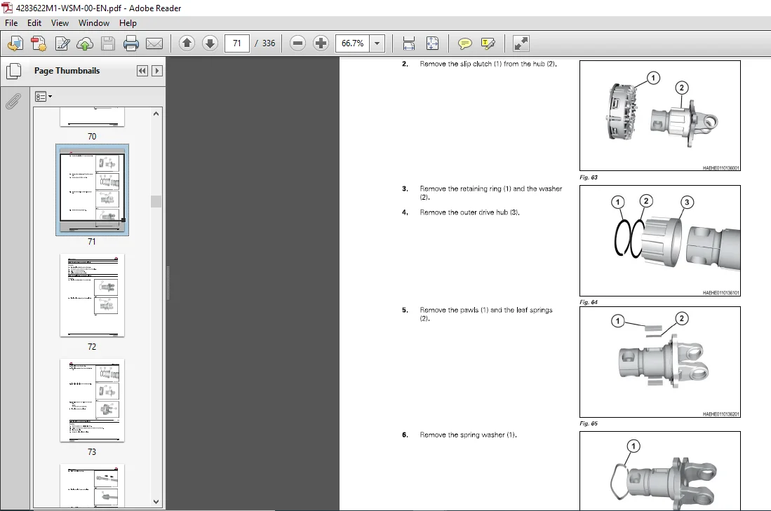
2 5 3 Remove the slip clutch 2-1 7
2 5 4 Disassemble the slip clutch 2-19
2 5 5 Examine the slip clutch 2-2 1
2 5 6 Assemble the slip clutch 2-2 1
2 5 7 lnstall the slip clutch 2-2 3
2 6 Overrunning clutch 2-25
2 6 1 Remove the overrunning clutch 2-2 5
2 6 2 Disassemble the overrunning clutch 2-2 6
2 6 3 Examine the overrunning clutch 2-2 8
2 6 4 Assemble the overrunning clutch 2-2 8
2 6 5 lnstall the overrunning clutch 2-2 9
2 7 Cutterbed driveline 2-32
2 7 1 Remove the cutterbed driveline 2-3 2
2 7 2 lnstall the cutterbed driveline 2-3 2
2 8 Conditioner drivelines 2-34
2 8 1 Remove the conditioner drivelines 2-34
2 8 2 Examine the conditioner drivelines 2-3 6
2 8 3 lnstall the conditioner drivelines 2-3 6
2 9 Universal joint bearing replacement 2-39
2 9 1 Disassemble a universal joint 2-3 9
Rotary Dise Mowers
2 9 2 Examine an universal joint 2-4 1
2 9 3 Assemble an universal joint 2-4 1
Quick disconnect 2-44
2 10 1 Disassemble the quick disconnect 2-4 4
2 10 2 Examine the quick disconnect 2-4 5
2 10 3 Assemble the quick disconnect 2-4 5
Belts – 4 m (13 ft) header 2-47
2 1 1 1 Belt maintenance 2-4 7
2 1 1 2 Belt inspection 2-4 7
2 1 1 3 Adjust the conditioner belt 2-4 7
2 1 1 4 Replace the conditioner belt 2-4 7
2 1 1 5 Adjust the helper roll belt 2-4 9
2 1 1 6 Replace the helper roll belt 2-4 9
2 1 1 7 Adjust the header drive belt 2-5 0
2 1 1 8 Replace the header drive belt 2-5 0
Belts – 5 m (16 ft) header 2-52
2 1 2 1 Belt maintenance 2-5 2
2 1 2 2 Adjust the conditioner belt 2-5 2
2 1 2 3 Replace the conditioner belt 2-5 3
2 1 2 4 Adjust the center cage belts 2-5 4
2 1 2 5 Replace the center cage belt 2-5 4
2 1 2 6 Adjust the header drive belt 2-5 5
2 1 2 7 Replace the header drive belt 2-5 5
Conditioner gearcase lubrication 2-57
2 1 3 1 Plug location -conditioner gearcases 2-5 7
2 1 3 2 Examine the gearcase oil level 2-5 8
2 1 3 3 Change the gearcase oil 2-5 9
Conditioner gearcase – 4 m (13 ft) header 2-60
2 1 4 1 Conditioner gearcase components – 4 m (1 3 ft) 2-6 0
2 1 4 2 Remove the conditioner gearcase – 4 m (1 3 ft) 2-6 1
2 1 4 3 Disassemble the conditioner gearcase – 4 m (1 3 ft) 2-6 2
2 1 4 4 Examine the conditioner gearcase – 4 m (1 3 ft) 2-6 3
2 1 4 5 Assemble the conditioner gearcase – 4 m (1 3 ft) 2-6 5
2 1 4 6 lnstall the conditioner gearcase – 4 m (1 3 ft) 2-6 9
Conditioner gearcase – 5 m (16 ft) header 2-71
2 1 5 1 Conditioner gearcase components – 5 m (1 6 ft) 2-7 1
2 1 5 2 Remove the conditioner gearcase – 5 m (1 6 ft) 2-7 1
2 1 5 3 Disassemble the conditioner gearcase – 5 m (1 6 ft) 2-7 3
2 1 5 4 Examine the conditioner gearcase – 5 m (1 6 ft) 2-7 5
2 1 5 5 Assemble the conditioner gearcase – 5 m (1 6 ft) 2-7 6
2 1 5 6 lnstall the conditioner gearcase – 5 m (1 6 ft) 2-8 1
Header drive gearbox 2-84
2 1 6 1 Plug location -header drive gearbox 2-8 4
2 1 6 2 Examine the gearbox oil level 2-8 4
2 1 6 3 Change the gearbox oil 2-8 4
2 1 6 4 Header drive gearbox components 2-8 6
2 1 6 5 Remove the header drive gearbox 2 -8 7
2 1 6 6 Disassemble the header drive gearbox 2-90
2 1 6 7 Assemble the header drive gearbox 2-9 2
2 1 6 8 lnstall the header drive gearbox 2-9 5
Cutterbed drive gearbox 2-99
2 1 7 1 Plug location -cutterbed drive gearbox 2-99
2 1 7 2 Examine the gearbox oil level 2-99
2 17 3 Change the gearbox oil 2-99
2 1 7 4 Remove the cutterbed drive gearbox 2-10 0
2 1 7 5 4 m(1 3 ft)header 2-10 5
2 17 5 1 Cutterbed drive gearbox components 2-10 5
Rotary Dise Mowers
4283622M1
Table of contents
2 17 5 2 Disassemble the cutterbed drive gearbox 2-106
2 17 5 3 Assemble the cutterbed drive gearbox 2-108
2 17 6 5 m ( 1 6 ft) header 2-1 1 1
2 17 6 1 Cutterbed drive gearbox components 2-1 1 1
2 17 6 2 Disassemble the cutterbed drive gearbox 2-1 1 2
2 17 6 3 Assemble the cutterbed drive gearbox 2-1 1 3
2 17 7 lnstall the cutterbed drive gearbox 2-1 1 6
2 18 Swivel gearbox 2-1 21
2 1 8 1 Plug location -swivel gearboxes 2-1 2 1
2 1 8 2 Examine the gearbox oil level 2-1 2 1
2 1 8 3 Change the gearbox oil 2-1 2 1
2 1 8 4 Remove the swivel gearbox 2-1 2 2
2 1 8 5 lnstall the swivel gearbox 2-1 2 2
2 1 8 6 Swivel gearbox – 4 m ( 1 3 ft) header 2-1 2 4
2 1 8 6 1 Swivel gearbox components 2-1 2 4
2 1 8 6 2 Disassemble the swivel gearbox 2-1 2 5
2 1 8 6 3 Assemble the swivel gearbox 2-1 2 9
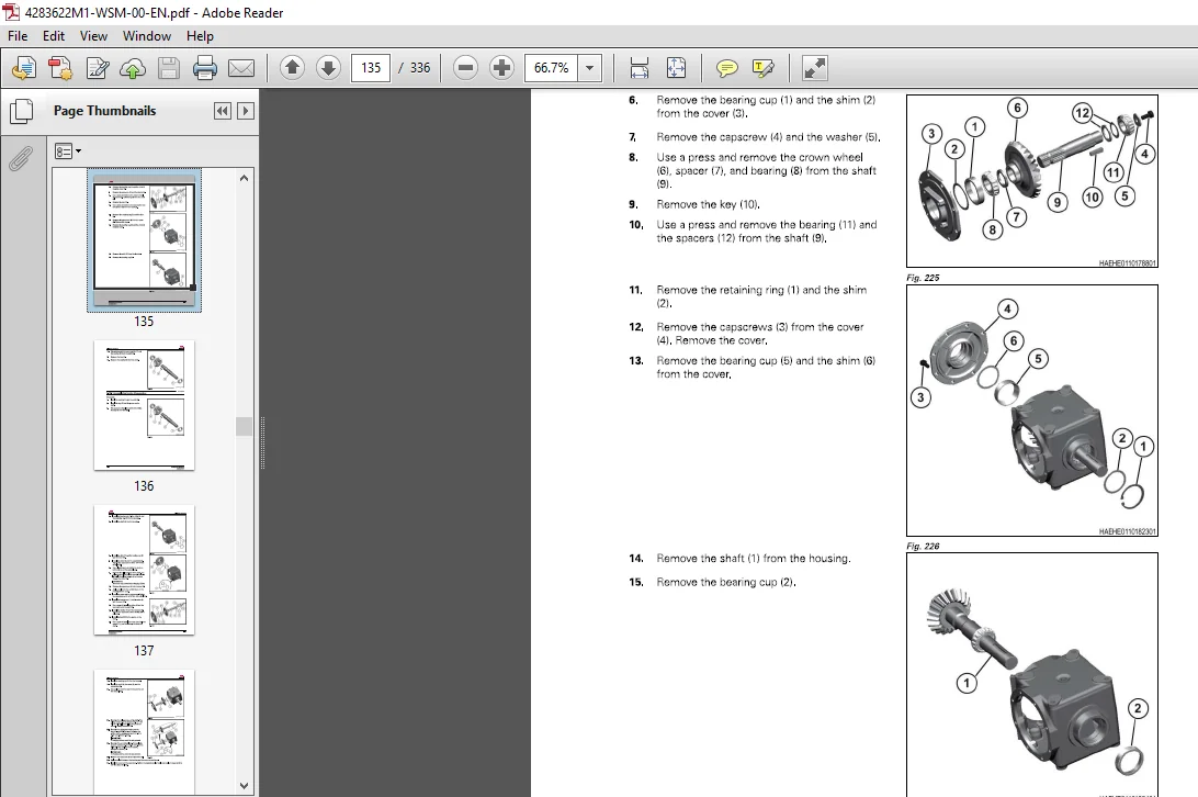
2 1 8 7 Swivel gearbox – 5 m ( 1 6 ft) header 2-1 3 6
2 1 8 7 1 Swivel gearbox components 2-1 3 6
2 1 8 7 2 Disassembling the swivel gearbox 2-1 3 7
2 1 8 7 3 Assemble the swivel gearbox 2-1 4 1
3 Hydraulic system 3-1
3 1 General hydraulic information 3-3
3 2 Steering cylinder 3-4
3 2 1 Remove the steering cylinder 3-4
3 2 2 lnstall the steering cylinder 3-5
3 3 Lift cylinders 3-6
3 3 1 General lift cylinder information 3-6
3 3 2 Remove a lift cylinder 3-6
3 3 3 lnstall a lift cylinder 3-7
3 4 Header angle cylinder 3-9
3 4 1 Remove the header angle cylinder 3-9
3 4 2 lnstall the header angle cylinder 3-9
3 5 Conditioner tension cylinder 3-11
3 5 1 Remove a tension cylinder 3-1 1
3 5 2 Tension cylinder components 3-1 3
3 5 3 lnstall a tension cylinder 3-1 3
3 6 Hydraulic cylinder repair 3-16
3 6 1 Examine the cylinder assembly 3-1 6
3 6 2 Repair a wire ring type cylinder 3-1 6
3 6 3 Repair a single acting cylinder 3-1 7
3 7 Accumulator, if equipped 3-19
3 7 1 Examine the accumulator charge pressure 3-1 9
3 7 2 Charge an accumulator 3-2 1
3 7 3 Discharge an accumulator 3-2 3
3 7 4 Remove the accumulator 3-2 4
3 7 5 lnstall the accumulator 3-2 6
3 8 Conditioner tension valve 3-28
3 8 1 Remove the tension valve 3-2 8
3 8 2 Disassemble the tension valve 3-2 9
3 8 3 Examine the tension valve 3-2 9
3 8 4 Assemble the tension valve 3-3 0
3 8 5 lnstall the tension valve 3-3 0
3 8 6 Adjust the conditioner roll pressure 3-3 1
3 8 6 1 lncrease the conditioner roll pressure 3-3 1
Rotary Dise Mowers
4283622M1
Table of contents
3 8 6 2 Decrease the conditioner roll pressure 3-3 2
4 Electrical system 4-1
4 1 Basic troubleshooting information 4-3
4 1 1 Basic troubleshooting procedures 4-3
4 1 2 Tools 4-4
4 1 3 Continuity check 4-4
4 1 4 Voltage check 4-5
4 2 Connectors 4-6
4 2 1 Examine a connector 4-6
4 2 2 Terminal numbers 4-6
4 2 3 Dielectric grease 4-7
4 2 4 Pins and sockets 4-7
4 2 5 Replace a Packard connector 4-8
4 2 6 Replace an AMP connector 4-8
4 3 Examine the lighting 4-10
4 3 1 Machine lamp plug wiring diagram -North America 4-1 1
5 Flotation 5-1
5 1 Header flotation 5-3
5 1 1 Adjust the header flotation 5-3
5 2 Flotation springs 5-4
5 2 1 Remove the flotation springs 5-4
5 2 2 Disassemble the flotation springs 5-5
5 2 3 Assemble the flotation springs 5-5
5 2 4 lnstall the flotation springs 5-5
6 Cutterbar 6-1
6 1 Lubrication 6-3
6 1 1 Cutterbed oil level 6-3
6 1 2 Change the cutterbed oil 6-3
6 2 Cutterbed inspection 6-5
6 3 Dises 6-6
6 3 1 Dise maintenance 6-6
6 3 2 Replace a dise 6-6
6 3 3 Replace a dise spindle assembly 6-7
6 4 Knives 6-9
6 4 1 Knife wedging under dise 6-9
6 4 2 Knife inspection 6-9
6 4 3 Dise rotation 6-10
6 4 4 Replace a fixed blade knife 6-10
6 4 5 Replace a quick change knife 6-1 1
6 4 6 Replace a knife quick change spring 6-1 2
6 4 7 Knife type 6-1 2
6 4 8 Knife hardware inspection 6-1 3
7 Conditioner 7-1
7 1 Conditioner adjustments 7-3
7 1 1 Conditioner 7-3
7 1 2 Conditioner spacing 7-3
7 1 2 1 Adjust the conditioner roll spacing 7-3
7 1 3 Adjust the conditioner spacing indicator 7-4
7 1 4 Conditioner roll pressure 7-4
7 1 4 1 lncrease the conditioner roll pressure 7 -4
7 1 4 2 Decrease the conditioner roll pressure 7-5
7 1 5 Adjust the conditioner roll timing – 5 m (1 6 ft) 7-5
Rotary Dise Mowers
4283622M1
Table of contents
7 1 6 Adjust the conditioner roll timing – 4 m (1 3 ft) 7-6
7 2 Examine the conditioner rolls 7-7
7 3 Top conditioner roll 7-8
7 3 1 Remove the top conditioner roll 7-8
7 3 2 lnstall the top conditioner roll 7-1 2
7 4 Bottom conditioner roll 7-17
7 4 1 Remove the bottom conditioner roll 7-1 7
7 4 2 lnstall the bottom conditioner roll 7-18
7 5 Helper roll – 4 m (1 3 ft) 7-21
7 5 1 Remove the helper roll – 4 m (1 3 ft) 7-2 1
7 5 2 lnstall the helper roll – 4 m (1 3 ft) 7-2 4
7 6 Helper roll – 5 m (1 6 ft) 7-27
7 6 1 Remove the helper roll – 5 m (1 6 ft) 7-2 7
7 6 2 lnstall the helper roll – 5 m (1 6 ft) 7-3 0
7 7 Auger stripper – 5 m (1 6 ft) header 7-35
7 7 1 Adjust the auger strippers 7-3 5
7 7 2 Replace the auger strippers 7-3 5
8 Chassis 8-1
8 1 Strut and lift arms 8-3
8 1 1 Remove the strut and lift arm 8-3
8 1 2 Disassemble the strut 8-4
8 1 3 Assemble the strut 8-5
8 1 4 lnstall the strut and lift arm 8-6
8 2 3-point hitch 8-8
8 2 1 Remove the 3-point hitch 8-8
8 2 2 lnstall the 3-point hitch 8-9
8 3 Drawbar hitch 8-11
8 3 1 Remove the drawbar hitch 8-1 1
8 3 2 lnstall the drawbar hitch 8-1 2
8 4 Tongue 8-14
8 4 1 Remove the tangue 8-1 4
8 4 2 Examine the tangue 8-1 5
8 4 3 lnstall the tangue 8-1 6
9 Spindles and wheels 9 -1
9 1 lnstall the wheels 9 -3
9 2 Lubricate the wheel bearings 9 -4
1 0 Diagrams 10-1
1 0 1 How to read wiring schematics 10-3
10 1 1 Diagram numbers 10-3
10 1 2 Location grids 10-3
1 0 2 Diagram symbols and abbreviations 10-5
10 2 1 Harness and connector identification 10-5
10 2 2 Splices 10-5
10 2 3 Device identification numbers 10-5
1 0 3 Electrical diagrams 10-7
10 3 1 Harness abbreviations 10-7
10 3 2 Wire colors 10-7
10 3 3 Electrical diagram 10-9
1 0 4 Circuit table 10-11
1 0 5 Connector table 10-13
1 0 6 Hydraulic schematic 10-1 5
Rotary Dise Mowers
4283622M1
Table of contents
11 Index lndex-1
Rotary Dise
MASSEY FERGUSON EU HAY EQUIPMENT 1393 1395 ROTARY DISC MOWER SERVICE MANUAL – PDF DOWNLOAD:
IMAGES PREVIEW OF THE MANUAL:
PLEASE NOTE:
- This is not a physical manual but a digital manual – meaning no physical copy will be couriered to you. The manual can be yours in the next 2 mins as once you make the payment, you will be directed to the download page IMMEDIATELY.
- This is the same manual used by the dealers inorder to diagnose your vehicle of its faults.
- Require some other service manual or have any queries: please WRITE to us at [email protected]
S.V

Thaddeus –
Awaiting download. Service was quick and simple.