Massey Ferguson EU Tractor MF4600 Series Tractors 4608 4609 4610 Service Manual – PDF DOWNLOAD
Original price was: $53.95.$33.95Current price is: $33.95.
Massey Ferguson EU Tractor MF4600 Series Tractors 4608 4609 4610 Service Manual – PDF DOWNLOAD
Description
Massey Ferguson EU Tractor MF4600 Series Tractors 4608 4609 4610 Service Manual – PDF DOWNLOAD
DESCRIPTION:
Massey Ferguson EU Tractor MF4600 Series Tractors 4608 4609 4610 Service Manual – PDF DOWNLOAD
Correct part description and part number
Model number of the machine
Serial number of the machine
Units of measurement:
Massey Ferguson EU Tractor MF4600 Series Tractors 4608 4609 4610 Service Manual – PDF DOWNLOAD
1 Introduction 1-1
1 1 Introduction 1-3
1 1 1 The service manual 1-3
1 1 2 Replacement parts 1-3
1 1 3 Units of measurement 1-3
1 1 4 Machine identification 1-3
1 1 5 Serial number plate 1-4
1 1 6 Engine identification 1-4
1 1 7 Chassis number 1-5
1 2 Specifications 1-6
1 2 1 Engine specifications 1-6
1 2 2 Electrical specifications 1-6
1 2 3 Transmission specifications 1-7
1 2 4 Power takeoff specifications 1-7
1 2 5 Front axle specifications 1-7
1 2 6 Rear axle specifications 1-8
1 2 7 Brake specifications 1-8
1 2 8 Hydraulic specifications 1-8
1 2 9 Fuel specifications 1-8
1 2 10 Operating slope angle 1-9
1 2 1 1 Lubrication specifications 1-9
1 2 1 2 Capacities 1-10
1 2 1 3 Maximum load capacity 1-10
1 2 1 4 Wheel bolt torque chart 1-1 1
1 2 1 5 Tire inflation pressures 1-1 2
1 3 General dimensions 1-14
1 3 1 Platform tractor dimensions 1-1 4
1 3 2 Cab tractor dimensions 1-1 5
1 4 Lubrication / fill points 1-17
1 4 1 Lubrication and maintenance chart 1-1 7
1 4 2 Initial lubrication and maintenance chart 1-1 8
1 4 3 Lubrication fill and drain locations 1-1 9
1 5 General precautions for disassembly and installation 1-20
1 5 1 Precautions for disassembling and installing 1-20
1 5 2 Precautions when installing according to standards parts 1-20
1 6 Tightening torque chart 1-23
1 7 Conversion table 1-25
2 Safety 2-1
2 1 Introduction 2-3
2 1 1 Safety alert symbol 2-3
2 1 2 Informational messages 2-3
2 1 3 Safety messages 2-3
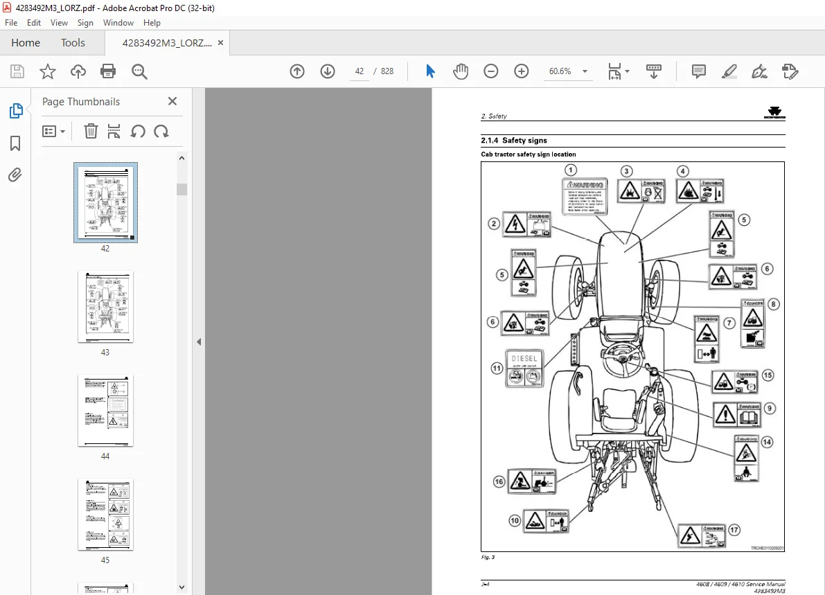
2 1 4 Safety signs 2-4
2 2 Operation 2-11
2 2 1 Prepare for operation 2-1 1
2 2 2 Roll over protective structure 2-1 1
2 2 3 General information 2-1 1
2 2 4 Personal protective equipment 2-1 5
2 2 5 Seat instruction 2-1 5
2 2 6 Shield and guards 2-1 5
4608 I 4609 I 4610 Service Manual
4283492M3
Table of contents
2 2 7 Power takeoff safety 2-16
2 2 8 Exhaust warning 2-17
2 2 9 Flying debris 2-17
2 3 Travel on public roads 2-18
2 4 Maintenance 2-20
2 4 1 General maintenance information 2-2 0
2 4 2 Fire prevention and first aid 2-2 1
2 4 3 High pressure leaks 2-2 2
2 4 4 Engine safety 2-2 3
2 4 5 Fuel safety 2-2 4
2 4 6 Battery safety 2-2 5
2 4 7 Tire safety 2-2 5
2 4 8 Replacement parts 2-2 6
3 Engine 3-1
3 1 Component access 3-3
3 1 1 Opening the engine cover 3-3
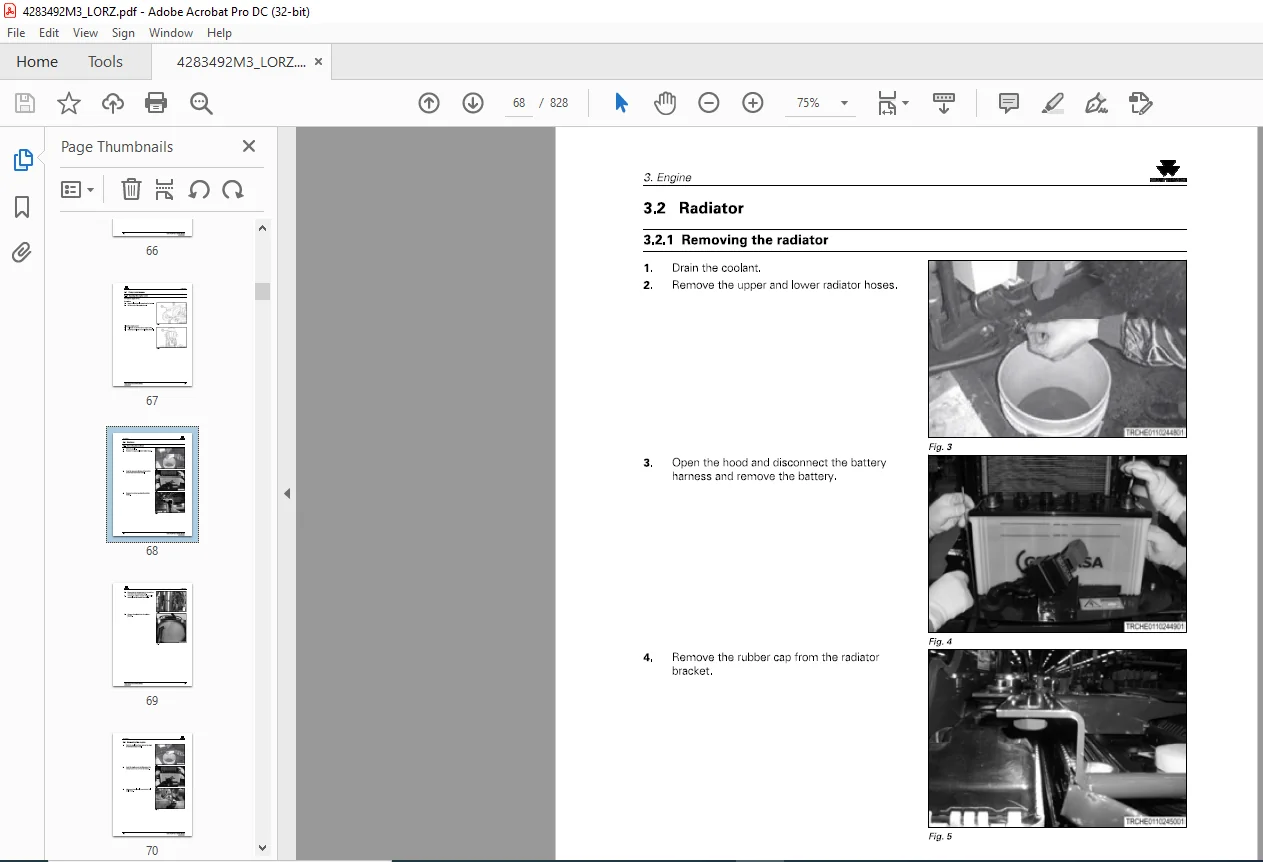
3 2 Radiator 3-4
3 2 1 Removing the radiator 3-4
3 3 Removing the engine 3-6
3 4 Installing the engine 3-1 o
3 5 Fuel tank 3-11
3 5 1 Removing the fuel tank 3-11
3 6 Electronic diagnostic tool 3-14
3 6 1 Engine service tool software license 3-14
3 6 2 Connecting the electronic diagnostic tool 3-14
3 7 Engine service manual 3-15
3 7 1 Insert the engine service manual here 3-15
4 Power train 4-1
4 1 Separating the engine from the front transmission 4-3
4 2 Separating the front and mid-transmission housings 4-9
4 3 Separating the mid and rear transmission housings 4-13
4 4 Separating the rear axle from the rear transmission case 4-17
4 5 Attaching the rear axle to the rear transmission case 4-19
4 6 Power shuttle transmission 4-20
4 7 Power train 4-23
4 8 Gear ratios 4-26
4 9 Shuttle clutch 4-28
4 9 1 Assembling precautions for power shuttle 4-2 9
4 10 Clutch pack 4-30
4 10 1 Reverse clutch pack components 4-3 0
4 10 2 Disassembling the reverse clutch 4-3 1
4 11 Input gears 4-32
4 11 1 Removing the input gear 4-3 2
4 11 2 Disassembling the input gear 4-3 2
4 11 3 Assembling the input gears 4-3 3
4 11 4 Disassembling the rear and mid-transmission housing 4-34
4 11 5 Input gears 4-36
4 12 Transmission main change gears 4-40
4 12 1 Assembling precautions for main gear system 4-4 1
4 12 2 Main shift lever 4-4 2
4 12 3 Assembling precautions for the main shift lever 4-4 3
4 12 4 Disassembling the high-low gear 4-4 4
4608 I 4609 I 467 0 Service Manual
4283492M3
Table of contents
4 13 Creeper gear 4-45
4 13 1 Creeper gear components 4-4 5
4 13 2 Disassembling the creeper gear 4-4 5
4 13 3 Assembling the creeper gear 4-4 9
4 14 Transmission range change gears 4-53
4 14 1 Range gear shift 4-5 3
4 14 2 Installing the range gear shift 4-54
4 14 3 Range shift linkage 4-55
4 14 4 Independent power takeoff 4-56
4 14 5 Power takeoff clutch 4-5 7
4 14 6 Assembling power takeoff precautions 4-5 8
4 14 7 Four-wheel drive gears, if equipped 4-5 8
4 14 8 Assembling four-wheel drive, if equipped 4-59
4 14 9 Four-wheel drive gear system 4-60
4 14 10 Two wheel-drive gear system 4-61
4 14 11 Power takeoff speed 4-61
4 14 12 Power takeoff lever 4-63
4 14 13 Power takeoff link check system 4-63
4 14 14 Low profile lever 4-63
5 Cab and platform 5-1
5 1 Platform 5-3
5 1 1 Removing the platform 5-3
5 1 2 Removing the floor mat and steps 5-11
5 1 3 Installing the floor mats and steps 5-12
5 2 Cab 5-13
5 2 1 Removing the cab 5-13
5 2 2 Installing the cab 5-19
5 2 3 Removing the cab roof 5-2 0
5 2 4 Installing the cab roof 5-2 0
5 2 5 Opening the roof 5-2 1
5 2 6 Removing the door 5-2 2
5 2 7 Installing the door 5-2 2
5 2 8 Adjusting the door tilt 5-2 4
5 2 9 Adjusting the opening angles of the door 5-2 4
5 2 10 Installing the door lock 5-2 5
5 2 11 Relay position 5-2 6
5 2 12 Cab lamp 5-2 7
5 2 13 Wiper and flood light switches 5-2 7
5 2 14 Air conditioner control panel 5-2 8
5 2 15 Air conditioning dual pressure switch 5-2 8
5 2 16 Cab wire harness 5-2 9
5 2 17 Installing the speaker system 5-2 9
5 2 18 Installing the antenna assembly 5-3 1
5 3 Seat 5-34
5 3 1 Removing the seat 5-34
5 3 2 Installing the seat 5-35
5 4 Roll over protective structure 5-36
5 4 1 Removing the roll over protective structure 5-36
5 4 2 Installing the roll over protective structure 5-36
5 5 Steering column 5-37
5 5 1 Removing the steering column 5-3 7
5 5 2 Installing the steering column 5-3 7
5 6 Steering wheel 5-38
5 6 1 Removing the steering wheel 5-3 8
5 6 2 Installing the steering wheel 5-3 8
4608 I 4609 I 4610 Service Manual
4283492M3
Table of contents
5 7 Mirrors 5-39
5 7 1 Adjusting the mirror arm assembly 5-39
5 8 Air conditioning system 5-41
5 8 1 Air conditioner outline 5-4 1
5 8 2 Air conditioner system specifications 5-4 1
5 8 3 Drain hoses 5-4 2
5 8 4 Air conditioner hoses 5-4 3
5 8 5 Heater hose 5-4 5
5 8 6 Installing the insulator 5-4 8
5 8 7 Compressor 5-4 9
5 8 8 Condenser 5-5 0
5 8 9 Receiver dryer 5-5 1
5 8 10 Air conditioner unit 5-5 1
5 8 11 Expansion valve 5-5 2
5 8 12 Air conditioning dual pressure switch 5-5 2
5 8 13 Thermostat 5-5 3
5 8 14 Air conditioner operation 5-5 3
5 8 15 Air conditioner inspection and maintenance 5-5 3
5 8 16 Refrigerant amount check 5-54
5 8 17 Air conditioner compressor belt 5-55
5 8 18 Adjusting the air conditioner compressor belt 5-56
5 8 19 Servicing the condenser 5-56
5 8 2 0 Changing the air conditioner filter 5-5 8
5 8 2 1 Maintenance 5-60
5 8 2 2 Removing the air conditioner compressor 5-60
5 8 2 3 Installing the air conditioner compressor 5-61
5 8 2 4 Removing the condenser 5-62
5 8 2 5 Installing the condenser 5-63
5 8 2 6 Removing the receiver dryer 5-63
5 8 2 7 Installing the receiver dryer 5-64
5 8 2 8 Removing the air conditioner unit 5-64
5 8 2 9 Air conditioner control lever cable 5-65
5 8 3 0 Shutter for inside/outside air control 5-65
5 8 3 1 Assembling the air conditioner and relative components 5-66
5 8 3 2 Safety precautions when charging the refrigerant 5-67
5 8 3 3 Connecting the service gauge manifold 5-69
5 8 34 Evacuating the air conditioning system 5-69
5 8 35 Preforming airtight check 1 5-7 0
5 8 36 Preforming the airtight check 2 5-7 0
5 8 3 7 Charging from the high pressure side 5-7 1
5 8 3 8 Charging from the low pressure side 5- 7 2
5 8 39 Detaching the service gauge manifold 5-7 4
5 9 Troubleshooting the air conditioner system 5-75
6 Frame and axles 6-1
6 1 Hydrostatic steering 6-3
6 1 1 Construction 6-3
6 1 2 Major components 6-4
6 1 3 Orbit roll disassembly 6-4
6 1 4 Disassembling the gerotor side 6-5
6 1 5 Disassembling the control side 6-6
6 1 6 Inspecting the orbit roll 6-9
6 1 7 Assembling the control side 6-9
6 1 8 Assembling the gerotor side 6-12
6 1 9 Orbit roll specifications 6-14
6 1 10 Troubleshooting 6-14
6 2 Fender 6-17
4608 I 4609 I 467 0 Service Manual
4283492M3
Table of contents
6 2 1 Removing the fender 6-17
6 2 2 Installing the fender 6-18
6 3 Engine cover 6-19
6 3 1 Removing the engine cover 6-1 9
6 3 2 Installing the engine cover 6-1 9
6 3 3 Head lamp and engine cover net 6-1 9
6 3 4 Side cover 6-20
6 4 Three-point linkage and drawbar 6-21
6 4 1 Three-point linkage 6-21
6 4 1 1 Draw bar 6-26
6 4 1 2 Maintaining drawbar components 6-2 6
6 4 2 Removing the lift cylinder case 6-27
6 5 Rear axle 6-29
6 5 1 General Information 6-29
6 5 2 Rear axle and brakes 6-29
6 5 3 Rear differential lock system and housing 6-3 1
6 6 Rear axle housing and differential gears 6-32
6 6 1 Disassembling the rear axle housing 6-3 2
6 6 2 Inspecting the rear axle and the brakes 6-3 4
6 6 3 Brake discs 6-3 4
6 6 4 Separator plates 6-3 5
6 7 Ring gear and pinion 6-36
6 7 1 Removing the ring gear and the pinion 6-3 6
6 7 2 Disassembling the ring gear and the pinion 6-3 7
6 7 3 Inspecting the ring gear and pinion assembly 6-38
6 7 4 Assembling the ring gear and the pinion 6-38
6 7 5 Installing the ring gear and the pinion 6-4 2
6 7 6 Backlash specification 6-4 2
6 7 7 Thrust collar specification 6-4 3
6 7 8 Tooth contact pattern 6-4 3
6 7 9 Assembling the pinion bevel 6-4 5
6 8 Brakes 6-46
6 8 1 Disassembling the brakes 6-47
6 8 2 Inspecting the brake discs and the separator plates 6-47
6 8 3 Checking the brake adjustment 6-47
6 8 4 Adjusting the brakes 6-48
6 9 Differential 6-49
6 9 1 Differential lock 6-4 9
6 10 Front axle 6-51
6 10 1 Removing the front axle 6-5 1
6 10 2 Front axle component inspection 6-5 2
6 10 3 Installing the front axle 6-5 4
6 10 4 Front axle components 6-5 5
6 10 5 Front axle specifications 6-57
6 10 6 Four-wheel drive shaft components 6-57
6 10 7 Hydraulic steering 6-58
6 10 8 T wo-wheel drive front axle component 6- 6 0
6 10 9 T wo-wheel drive steering controller system 6- 6 3
6 10 10 T wo-wheel drive tie rod system 6- 6 3
6 11 Front differential (four-wheel drive only) 6-64
6 1 1 1 Disassembling the pinion carrier 6- 6 4
6 1 1 2 Overhauling the pinion carrier 6- 6 5
6 1 1 3 Inspecting the pinion carrier 6- 6 6
6 1 1 4 Assembling the pinion carrier 6- 6 6
6 1 1 5 Disassembling the differential gears 6- 6 7
6 1 1 6 Inspecting the differential gears 6- 6 7
4608 I 4609 I 4610 Service Manual
4283492M3
Table of contents
6 1 1 7 Assembling the differential gears 6- 6 8
6 1 1 8 Final drive components 6-7 0
6 1 1 9 Removing the wheel shaft seal/cover 6-7 1
6 1 1 10 Installing the wheel shaft seal/cover 6-7 2
6 1 1 1 1 Removing the front axle center section 6-7 4
6 1 1 1 2 Installing the front axle center section 6-7 4
6 1 1 1 3 Removing the front axle bracket oil seal 6-7 4
6 1 1 1 4 Installing the front axle bracket oil seal 6-7 5
6 12 Final drive housing (four-wheel drive only) 6-76
6 1 2 1 Disassembling the final drive housing 6-7 6
6 1 2 2 Inspecting the final drive housing 6-7 7
6 1 2 3 Assembling the final drive housing 6-7 8
6 1 2 4 Tie rod assembly 6-8 0
6 13 Front wheel alignment 6-81
6 1 3 1 Adjusting the front wheel alignment 6-8 1
6 1 3 2 Steering free play 6-8 1
6 14 Front axle troubleshooting 6-82
7 Electrical 7-1
7 1 Wire color chart 7-3
7 2 Power shuttle general information 7-5
7 3 Wiring diagrams 7-6
7 3 1 Battery wiring diagram 7-7
7 3 2 Instrument panel wiring diagram 7-8
7 3 3 Head lamp wiring diagram 7-9
7 3 4 Controller wiring diagram 7-10
7 3 5 Cab wiring diagram 7-1 1
7 3 6 Main wiring diagram 7-1 2
7 3 6 1 7-1 3
7 3 6 2 7-1 3
7 3 7 Engine wiring diagram 7-1 4
7 3 7 1 7-1 5
7 3 8 Controller area wiring diagram 7-1 5
7 3 8 1 7-1 6
7 3 9 Cab 1 wiring diagram 7-1 6
7 3 9 1 7-18
7 3 10 Cab 2 wiring diagram 7-18
7 4 Instruments and controls 7-21
7 4 1 Removing the console 7-21
7 4 2 Mater panel s witch 7-21
7 4 3 Removing the instrument panel 7-22
7 4 4 Installing the instrument panel 7-24
7 4 5 Instrument panel switch location diagram 7-27
7 4 6 Cab switch location diagram 7-28
7 4 6 1 7-28
7 4 7 Lever guide s witch location diagram 7-29
7 4 8 Main fuse box – platform tractor 7-3 1
7 4 9 Main fuse box – cab tractor 7-3 3
7 5 Valves 7-35
7 5 1 Power shuttle valve 7-3 5
7 5 2 Power take-off valve 7-4 4
7 5 3 Solenoid valves 7-4 6
7 6 Position of the main electrical parts 7-50
7 6 1 Position of sub-change lever position sensor 7-50
7 6 2 Position of the air conditioner controller panel 7-50
7 6 3 Position of the air conditioner controller unit 7-5 1
4608 I 4609 I 467 0 Service Manual
4283492M3
Table of contents
7 6 4 Position of the cabin harness assembly 7-5 1
7 6 5 Position of the engine harness coupler 7-5 2
7 6 6 Position of the head lamp 7-5 2
7 6 7 Position of the horn 7-5 2
7 6 8 Position of the starter 7-5 3
7 7 Sensor initial adjustment 7-54
7 7 1 Calibrating the three-point hitch 7-54
7 7 2 Lift arm and draft sensor 7-5 7
7 7 3 Control lever 7-5 8
7 7 4 Fuse box 7-5 8
7 7 5 Depth dial 7-59
7 7 6 Lift lamp 7-59
7 7 7 Main switch 7-60
7 7 8 Calibrating the clutch pedal switch and sensor 7-60
7 7 9 Clutch pedal 7-62
7 7 10 Clutch pedal sensor 7-63
7 7 11 Clutch pedal switch 7-63
7 7 12 Forward/reverse lever 7-64
7 7 13 Calibrating the clutch initial time 7-64
7 7 14 Range shift lever 7-65
7 7 15 Gear shift lever 7-65
7 7 16 Parking lever switch 7-66
7 7 17 Brake pedal switch 7-66
7 7 18 Throttle lever 7-67
7 7 19 Instrument panel 7-67
7 8 Electrical and hydraulic control system 7-68
7 9 Main clutch system 7-70
7 10 Electronic diagnostic tool 7-72
7 10 1 Engine service tool software license 7-7 2
7 10 2 Connecting the electronic diagnostic tool 7-7 2
7 11 Fault code tree 7-73
7 12 Diagnostic codes 7-75
7 12 1 SPN 1001 FMI 1 7-75
7 12 2 SPN 1001 FMI 2 7-7 8
7 12 3 SPN 1001 FMI 3 7-8 1
7 12 4 SPN 1002 FMI 1 7-8 4
7 12 5 SPN 1002 FMI 2 7-8 7
7 12 6 SPN 1002 FMI 3 7-9 0
7 12 7 SPN 1004 FMI 1 7-9 3
7 12 8 SPN 1004 FMI 2 7-96
7 12 9 SPN 1004 FMI 3 7-9 9
7 12 10 SPN 3 055 FMI 1 7-102
7 12 11 SPN 3 055 FMI 2 7-104
7 12 12 SPN 3 05 7 FMI 1 7-106
7 12 13 SPN 3 05 7 FMI 2 7-108
7 12 14 SPN 3 15 1F MI 06 7-110
7 12 15 SPN 3 15 1F MI 07 7-113
7 12 16 SPN 3 15 1F MI 08 7-115
7 12 17 SPN 3 15 1F MI 09 7-118
7 12 18 SPN 3 15 2 FMI 04 7-12 1
7 12 19 SPN 3 156 FMI 08 7-12 4
7 12 2 0 SPN 3 156 FMI 09 7-12 7
7 12 2 1 SPN 3 35 1F MI 2 1 7-13 0
7 12 2 2 SPN 3 35 1F MI 2 2 7-13 3
7 12 2 3 SPN 3 35 2 FMI 2 1 7-136
7 12 2 4 SPN 3 35 2 FMI 2 2 7-139
4608 I 4609 I 4610 Service Manual
4283492M3
Table of contents
8 Hydraulics 8-1
8 1 Hydraulic schematic 8-3
8 1 1 Hydraulic schematic 8-5
8 2 Specifications 8-7
8 2 1 Power shuttle transmission specifications 8-10
8 3 Transmission oil cooler and lubrication 8-11
8 4 General service procedures 8-13
8 4 1 Transmission oil 8-1 3
8 4 2 Checking the transmission oil level 8-1 3
8 4 3 Changing the transmission oil and filter 8-1 3
8 5 Suction filter 8-15
8 5 1 Suction filter specifications 8-1 5
8 5 2 Suction filter operation 8-1 6
8 5 3 Suction filter maintenance 8-1 6
8 6 Gear pump 8-17
8 6 1 Main pump 8-17
8 6 2 Sub pump 8-18
8 7 Cylinders 8-19
8 7 1 Power steering cylinder 8-1 9
8 7 2 Main cylinder 8-21
8 7 3 Main cylinder specifications 8-23
8 7 4 Assist cylinder, if equipped 8-23
8 8 Valves 8-25
8 8 1 Main relief valve 8-25
8 8 2 Installing the main relief valve 8-2 6
8 8 3 Main relief valve specifications 8-2 6
8 8 4 Main control valve 8-27
8 8 5 Steering orbit roll 8-28
8 8 6 Slow return valve 8-29
8 8 7 Assembling precautions for the slo w return valve 8-30
8 8 8 Slo w return valve specifications 8-30
8 8 9 Safety valve 8-3 1
8 8 10 Assembling precautions for the safety valve 8-3 1
8 8 1 1 Safety valve specifications 8-3 1
8 8 1 2 Power takeoff control valve 8-3 2
8 8 1 3 Assembling precautions for the power takeoff control valve 8-3 3
8 8 1 4 Power takeoff control valve specifications 8-3 3
8 8 1 5 Reduce valve 8-3 4
8 8 1 6 Assembling precautions for the reduce valve 8-3 6
8 8 17 Reduce valve specifications 8-3 7
8 8 18 Control valve 8-3 7
8 8 1 9 Assembling precautions for the control valve 8-4 1
8 8 20 Control valve specifications 8-4 1
8 8 21 High-lo w valve ( P 1 type only) 8-4 2
8 8 22 Joystick valve ( J type only) 8-4 4
8 8 23 Joystick valve specifications 8-48
8 8 24 Boom valve operation 8-4 9
8 8 25 Bucket valve operation 8-5 4
8 8 2 6 Remote control valve 8-57
8 8 27 Remote control valve specifications 8-57
8 8 28 Removing the remote control valve 8-58
8 8 29 Remote control valve assembly 8-58
8 8 30 Installing the remote control valve 8-5 9
8 9 Parts and hydraulic diagrams 8-60
8 9 1 Front loader adapter 8 – 6 0
4608 I 4609 I 467 0 Service Manual
4283492M3
Table of contents
8 9 2 External auxiliary hydraulics 8-61
8 9 3 Hydraulic control linkage 8-62
8 9 4 Auxiliary hydraulic valves 8-65
8 9 5 Joystick link and lever 8-67
8 9 6 Position control sensor and lever 8-7 7
8 9 7 Adjusting the position control lever 8-7 8
8 9 8 Three-point linkage 8-79
8 9 9 Three-point linkage specifications 8-8 0
8 9 10 Drawbar 8-8 1
8 10 Hydraulic system troubleshooting 8-82
9 Index lndex-1
Appendix “A”
MASSEY FERGUSON EU TRACTOR MF4600 SERIES TRACTORS 4608 4609 4610 SERVICE MANUAL – PDF DOWNLOAD:
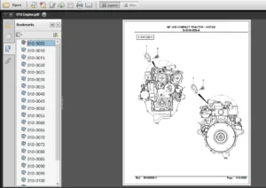
IMAGES PREVIEW OF THE MANUAL:
PLEASE NOTE:
- This is the SAME manual used by the dealers to troubleshoot any faults in your vehicle. This can be yours in 2 minutes after the payment is made.
- Contact us at [email protected] should you have any queries before your purchase or that you need any other service / repair / parts operators manual.
S.V


Stanley Erik –
next time