Massey Ferguson EU Tractor MF8700 Series Technician Service Manual – PDF DOWNLOAD
Original price was: $53.95.$31.95Current price is: $31.95.
Massey Ferguson EU Tractor MF8700 Series Technician Service Manual – PDF DOWNLOAD
Description
Massey Ferguson EU Tractor MF8700 Series Technician Service Manual – PDF DOWNLOAD
FILE DETAILS:
Massey Ferguson EU Tractor MF8700 Series Technician Service Manual – PDF DOWNLOAD
Format: PDF
Language: English
Brand: Massey Ferguson
MASSEY FERGUSON EU TRACTOR MF8700 SERIES TECHNICIAN SERVICE MANUAL – PDF DOWNLOAD:
TABLE OF CONTENTS:
Massey Ferguson EU Tractor MF8700 Series Technician Service Manual – PDF DOWNLOAD
1 General 1-1
1 1 Specifications 1-3
1 1 1 MF 87 00models 1-3
1 2 Forward speeds 1-13
1 2 1 Forward speed for all models with Dyna-VT transmission 1-1 3
1 3 Dimensions and weights 1-14
1 3 1 Dimensions and weights 1-14
1 4 Attachment points 1-16
1 4 1 Attachment points: Dyna-VT models with 5 t front linkage 1-1 6
1 4 2 Attachment points: Dyna-VT models without front linkage 1-17
1 5 Capacities 1-1 s
1 5 1 Capacities for models with a Tier 4F/Stage I V SCR Technology engine 1-1 9
1 5 2 Capacities for models with a Tier 2/Stage II engine Tier 3/Stage IIIA engineSCR
Technology 1-1 9
1 5 3 Accumulator pressure and volume 1-2 0
1 6 Tightening torques, retaining compounds and sealing products 1-21
1 6 1 Retaining compounds and sealing products 1-2 1
1 6 2 Tightening torques for screws and nuts 1-2 2
1 6 3 Tightening torques for hydraulic unions 1-2 6
1 7 Units of measurement 1-30
1 7 1 Conversion table 1-30
2 Error codes 2-1
2 1 Error codes 2-3
2 1 1 General table of faults 2-3
2 1 2 Indicator light panel 2-6
2 1 3 Indication of faults 2-1 3
2 1 4 Description of error code format 2-1 5
2 1 5 Instrument panel error codes Dyna-VT 2-17
2 1 6 AGCO Power Tier 3/Stage I I IA engine and Tier 4F/Stage I V SCR Technology
engine error codes 2-1 8
2 1 7 Dyna-VT transmission error codes 2-33
2 1 8 Front axle error codes Dyna-VT 2-37
2 1 9 Rear power take-off error codes Dyna-VT 2-38
2 1 1 0 Error codes for the high-pressure braking 2-40
2 1 1 1 Rear linkage error codes 2-40
2 1 1 2 Front power lift error codes 2-4 2
2 1 1 3 Armrest error codes 2-4 2
2 1 14 Hydraulic valve error codes 2-43
2 1 1 5 Air conditioning error codes 2-44
2 1 1 6 Error codes of the keypad in the pillar 2-46
2 1 17 Suspended cab error codes 2-47
3 Fuse box 3-1
3 1 Fuse box 3-3
3 1 1 Description of the main fuse box 3-3
3 1 2 Description of the secondary fuse box (depending on model) 3-1 3
3 1 3 Description of the secondary fuse box (depending on model) 3-1 8
Technician Service Book – series tractors MF 8700
ACT000616C
Table of contents
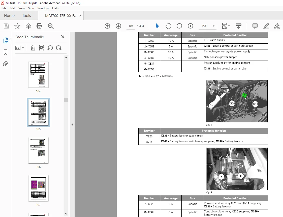
3 1 4 Battery isolator 3-2 1
4 Electrical diagrams 4-1
4 1 Electrical diagrams 4-3
4 1 1 Identification of electrical diagrams 4-3
4 1 2 Identification of electrical connectors from X1 to X5 00 4-5
4 1 3 Identification of electrical connectors from X5 01 to X1 000 4-17
4 1 4 Identification table for cable colors 4-2 6
4 1 5 Electrical diagrams 4-27
4 1 5 1 EF D00000_9 – Battery 1 2 V power supply points 4-27
4 1 5 2 EF D00000_ 1 0- Battery earth points 4-2 8
4 1 5 3 EF D001 00_ 16 – 4-wheel drive 4-30
4 1 5 4 EF D001 01 _ 1 6 – Differential lock 4-31
4 1 5 5 EF D001 05 _4 -Auxiliary hydraulic oil gage 4-31
4 1 5 6 EF D001 06 _27 -Rear power take-off 4-32
4 1 5 7 EF D001 07_ 14 -Front power take-off 4-33
4 1 5 8 EF D001 1 1 _ 29 -transmission Dyna-VT 4-34
4 1 5 9 EF D001 1 3_8 -Cigarette lighter 4-35
4 1 5 1 0 EF D001 14_31 – EA ME radio 4-36
4 1 5 1 1 EF D001 1 6_ 1 1 -Active suspended cab 4-37
4 1 5 1 2 EF D001 17 _35 -Automatic air conditioning unit power supply 4-38
4 1 5 1 3 EF D001 17 _36 -Automatic air conditioning 4-39
4 1 5 14 EF D001 17 _37 – Manual air conditioning 4-40
4 1 5 1 5 EF D001 17 _38 -Additional heater 4-4 1
4 1 5 16 EF D001 1 8 _8 – DOT Matrix 4-4 2
4 1 5 17 EF D001 1 9 _ 1 2 -Rear windscreen wiper 4-43
4 1 5 1 8 EF D001 2 0_ 1 1 -Front windscreen wiper 4-44
4 1 5 19 EF D001 2 1 _ 1 2 – Parking brake 4-4 5
4 1 5 2 0 EF D001 2 2 _7 -Fuel gage 4-46
4 1 5 2 1 EF D001 2 3_2 0 -lsobus 4-47
4 1 5 2 2 EF D001 2 3_27 -Auto-Guide™ 4-4 8
4 1 5 2 3 EF D001 2 3_2 8 – Datatronic CC D 4-49
4 1 5 2 4 EF D001 2 4_ 1 2 – Parklock 4-5 0
4 1 5 2 5 EF D001 2 5 _ 1 1 -Cab light 4-5 1
4 1 5 2 6 EF D001 2 6 _ 1 5 – Extreme cold weather heating with automatic air
conditioning 4-5 2
4 1 5 27 EF D001 2 6 _ 16 – Extreme cold weather heating with manual air
conditioning 4-5 3
4 1 5 2 8 EF D001 27 _9 – Left-hand pillar 1 2 V socket 4-5 4
4 1 5 2 9 EF D001 2 8 _ 1 9 -Cab power socket 4-5 5
4 1 5 30 EF D001 29_ 1 0- Diagnostics connector 4-56
4 1 5 31 EF D001 30_7 -Radar 4-57
4 1 5 32 EF D001 31 _32 -CAN network tractor (84 AWF engine) – 1/5 4-5 8
4 1 5 33 EF D001 31 32 -CAN network engine (84 AWF engine) – 2/5 4-5 9
4 1 5 34 EF D001 31 _32 -CAN networkAGCO Power (84 AWF engine) – 3/5 4-6 0
4 1 5 35 EF D001 31 32 -CAN network hitch (84 AWF engine) – 4/5 4-6 1
4 1 5 36 EF D001 31 32 -CAN network isobus (84 AWF engine) – 5/5 4-6 2
4 1 5 37 EF D00131 _4 2 -CAN network tractor (84 CWI engine) – 1/5 4-63
4 1 5 38 EF D00131 _4 2 -CAN network engine (84 CWI engine) – 2/5 4-64
4 1 5 39 EF D00131 _4 2 -CAN network hitch (84 CWI engine) -3/5 4-6 5
4 1 5 40 EF D00131 _4 2 -CAN network isobus (84 CWI engine) -4/5 4-66
4 1 5 4 1 EF D00131 _4 2 -CAN network AGCO Power (84 CWI engine) – 5/5 4-67
4 1 5 4 2 EF D00 1 32 _8 – Electric rear-view mirrors 4-6 8
4 1 5 43 EF D001 33_8 – Pneumatic seat 4-69
4 1 5 44 EF D00136 _54 – EAME direction indicators and hazard warning lights 4 -70
4 1 5 4 5 EF D00 1 36_5 5 – NA direction indicators and hazard warning lights 4-7 1
4 1 5 46 EF D00 1 37 27 – Number plate lighting 4-7 2
4 1 5 47 EF D00 1 38_39 – Side lights 4-73
Technician Service Book- series tractors MF 8700
ACT000616C
Table of contents
4 1 5 4 8 EF D001 39 _ 1 1 -Reversing light 4-74
4 1 5 49 EF D00140_4 4 – High beam lamps and low beam lamps on grille 4-7 5
4 1 5 5 0 EF D00140_4 5 – High beam lamps and low beam lamps on grille + hand
rail 4-76
4 1 5 5 1 EF D0014 1 _9 1 – EA ME work lights 4-77
4 1 5 52 EF D0014 1 _92- NA work lights 4-7 8
4 1 5 53 EF D00142_ 1 0- Brake lights 4-79
4 1 5 5 4 EF D00143_29 -Rotary beacon 4- 8 0
4 1 5 5 5 EF D00144 _9 -Control module 4- 8 1
4 1 5 5 6 EF D001 4 5 _ 1 5 – EA ME trailer connector 4- 82
4 1 5 57 EF D001 4 5 _ 16 – NA trailer connector 4- 8 3
4 1 5 5 8 EF D0014 8 _1 2- Audible alarm 4-84
4 1 5 5 9 EF D00149 _ 1 5 – Battery charge + start-up (84 AWF engine) 4- 8 5
4 1 5 6 0 EF D00149 _20 – Battery charge + start-up (84 CWl2 engine) 4- 86
4 1 5 6 1 EF D001 5 0_9 -Air filter vacuum sensor 4- 87
4 1 5 62 EF D001 5 1 _24 – E E M unit power supply AGCO Power (84 AWF engine)
4- 8 8
4 1 5 63 EF D001 5 1 _25 – engine electronic injection AGCO Power (84 AWF
engine) 4- 89
4 1 5 64 EF D001 5 1 _36 – E E M unit power supply AGCO Power (84 CWl2 engine)
4-90
4 1 5 6 5 EF D001 5 1 _37 – engine electronic injection AGCO Power (84 CWl2
engine) 4-9 1
4 1 5 66 EF D001 52_ 1 5 – DANA suspended front axle 4-92
4 1 5 67 EF D001 5 3_ 1 8 – Preheating power supply AGCO Power 4-93
4 1 5 6 8 EF D001 5 4 _ 5 -Fuel preheater 4-94
4 1 5 69 EF D001 57 _5 – Vistronic (84 AWF engine) 4-9 5
4 1 5 70 EF D001 57 9 – Vistronic (84 CWl2 engine) 4-96
4 1 5 7 1 EF D001 5 9 _ 1 5 – Hydraulic spool valves 4-97
4 1 5 72 EF D001 6 0_28 -Rear linkage and Dual Control 4-9 8
4 1 5 73 EF D0016 1 _ 12 -Front linkage 4-99
4 1 5 74 EF D001 62_9 – Dual Control linkage and trailed implements (T IC) 4-1 00
4 1 5 7 5 EF D001 63_ 1 1 -Console lighting 4-1 01
4 1 5 7 6 EF D00169_ 17 -Controller power supply – 1/ 5 4-1 02
4 1 5 7 7 EF D00169_ 17 -Controller power supply -2/5 4-1 03
4 1 5 7 8 EF D00169_ 17 -Controller power supply -3/5 4-1 04
4 1 5 7 9 EF D00169_ 17 -Controller power supply -4/5 4-1 05
4 1 5 8 0 EF D00169 _ 17 -Controller power supply – 5/5 4-1 06
4 1 5 8 1 EF D00172_7 -Front accessory connection socket 4-1 07
4 1 5 82 EF D00173_6 -Water in fuel sensor (84 AWF engine) 4-1 0 8
4 1 5 8 3 EF D00173_9 -Water in fuel sensor (84 CWl2 engine) 4-1 09
4 1 5 84 EF D00174_ 1 0- Air brake 4-1 1 0
4 1 5 8 5 EF D0017 5 – Tier4f/Stage I V AGCO Power engine _ 1/3 4-1 1 1
4 1 5 86 EF D0017 5 – Tier4f/Stage I V AGCO Power engine_2/3 4-1 12
4 1 5 87 EF D0017 5 – Tier4f/Stage I V AGCO Power engine_3/3 4-1 1 3
4 1 5 8 8 EF D0017 5 _7 – SCR Technology 4-1 14
4 1 5 89 EF D00176_ 12- ALO EAM E loader 4-1 1 5
4 1 5 90 EF D00176_ 13 -A LO NA loader 4-1 1 6
4 1 5 9 1 EF D00177 _5 -Auto-hitch 4-1 17
4 1 5 92 EF D0017 8 _6 – Steering SpeedSteer 4-1 1 8
4 1 5 93 EF D001 84 _6 -AgCommand ™ 4-1 1 9
5 Harnesses 5-1
5 1 Harnesses 5-5
5 1 1 Identification of harnesses 5-5
5 1 2 Harnesses 5-9
5 1 2 1 FAl200 – Engine harness 84 AWF – 1/ 4 5-9
5 1 2 2 FAl200 – Engine harness 84 AWF -2/ 4 5-1 0
Technician Service Book – series tractors MF 8700
ACT000616C
Table of contents
5 1 2 3 FAl 2 00 – Engine harness 84 AWF – 3 /4 5-1 1
5 1 2 4 FAl 2 00 – Engine harness 84 AWF – 4 /4 5-1 2
5 1 2 5 FAl 2 00 – Engine harness cab -ACW 0349940_ 1/2 5-1 3
5 1 2 6 FAl 2 00 – Engine harness cab -ACW 0349940_2/2 5-14
5 1 2 7 FAl 2 00 – Engine harness 84 CWl 2 – 1/3 5-1 5
5 1 2 8 FAl 2 00 – Engine harness 84 CWl 2 – 2/3 5-16
5 1 2 9 FAl 2 00 – Engine harness 84 CWl 2 – 3/3 5-17
5 1 2 1 0 FAl 2 0 1 -Front headlights harness – 4384 1 33_ 1/2 5-1 8
5 1 2 1 1 FAl 2 0 1 -Front headlights harness – 4384 1 33_2/2 5-1 9
5 1 2 1 2 FAl 2 02 -Fixed front axle harness with Auto-Guide™ 5-2 0
5 1 2 1 3 FAl 2 02 – Suspended front axle harness- 1/2 5-2 1
5 1 2 14 FAl 2 02 – Suspended front axle harness- 2/2 5-2 2
5 1 2 1 5 FAl 2 03 – Transmission harness – 1/5 5-2 3
5 1 2 16 FAl 2 03 – Transmission harness – 2/5 5-2 4
5 1 2 17 FAl 2 03 – Transmission harness – 3/5 5-2 5
5 1 2 1 8 FAl 2 03 – Transmission harness – 4/5 5-2 6
5 1 2 1 9 FAl 2 03 – Transmission harness – 5/5 5-27
5 1 2 2 0 FAl 2 1 0- Cab transmission harness – 1/9 5-2 8
5 1 2 2 1 FAl 2 1 0- Cab transmission harness – 2/9 5-29
5 1 2 2 2 FAl 2 1 0- Cab transmission harness -3/9 5-30
5 1 2 2 3 FAl 2 1 0- Cab transmission harness -4/9 5-31
5 1 2 24 FAl 2 1 0- Cab transmission harness – 5/9 5-32
5 1 2 2 5 FAl 2 1 0- Cab transmission harness -6/9 5-33
5 1 2 26 FAl 2 1 0- Cab transmission harness -7/9 5-34
5 1 2 27 FAl 2 1 0- Cab transmission harness – 8/9 5-35
5 1 2 2 8 FAl 2 1 0- Cab transmission harness -9/9 5-36
5 1 2 2 9 FAl 2 14 -Armrest harness _ 1/2 5-37
5 1 2 30 FAl 2 14 -Armrest harness _2/2 5-38
5 1 2 31 FAl 2 19 -Cab interior power socket harness (E EC) 5-39
5 1 2 32 FAl 2 19 -Cab interior power socket harness (NA) 5-40
5 1 2 33 FAl 2 2 3- Roof harness EAME -4389 179_ 1/2 5-4 1
5 1 2 34 FAl 2 2 3- Roof harness EAME -4389 179_2/2 5-42
5 1 2 35 FAl 2 2 3- Roof harness NA-4389 1 83_ 1/2 5-43
5 1 2 36 FAl 2 2 3- Roof harness NA -4389 1 83_2/2 5-44
5 1 2 37 FAl 2 2 5 – Electric rear- view mirror harness- 1/2 5-4 5
5 1 2 38 FAl 2 2 5 – Electric rear- view mirror harness- 2/2 5-46
5 1 2 39 FAl 2 27 – Roof harness with automatic air conditioning EA ME –
4389 1 8 0_ 1/2 5-47
5 1 2 40 FAl 2 27 – Roof harness with automatic air conditioning EA ME –
4389 1 8 0_2/2 5-4 8
5 1 2 4 1 FAl 2 27 – Roof harness with automatic air conditioning N A –
4389 1 84 _ 1/2 5-49
5 1 2 4 2 FAl 2 27 – Roof harness with automatic air conditioning NA –
4389 1 84_2/2 5-5 0
5 1 2 43 FAl 2 2 8 – Number plate lighting harness – 4 2 99633_ 1/2 5-5 1
5 1 2 44 FAl 2 2 8 – Number plate lighting harness – 4 2 99633_2/2 5-5 2
5 1 2 4 5 FAl 2 43 -Circuit breaker harness (84 AWF engine) – 1/2 5-5 3
5 1 2 46 FAl 2 43 -Circuit breaker harness (84 AWF engine) – 2/2 5-5 4
5 1 2 47 FAl 2 43 -Circuit breaker harness (84 AWF engine) – 1/2 5-5 5
5 1 2 4 8 FAl 2 43 -Circuit breaker harness (84 AWF engine) – 2/2 5-5 6
5 1 2 49 FAl 2 43 -Circuit breaker harness (84 CWl 2 engine) 5-57
5 1 2 5 0 FAl 2 5 2 – + 1 2 V battery harness 5-5 8
5 1 2 5 1 FAl 2 5 3- Hand rail harness -43902 6 2 _ 1/2 5-59
5 1 2 5 2 FAl 2 5 3- Hand rail harness -43902 6 2 _2/2 5-60
5 1 2 5 3 FAl 2 6 1 – lsobus harness – 43496 5 9 _ 1/2 5-6 1
5 1 2 5 4 FAl 2 6 1 – lsobus harness – 43496 5 9 _2/2 5-6 2
5 1 2 5 5 FAl 2 6 2 -Auto-Guide ™ engine harness 5-63
5 1 2 5 6 FAl 2 63 -Auto-Guide ™ cab adapter harness- 1/2 5-64
Technician Service Book- series tractors MF 8700
ACT000616C
Table of contents
5 1 2 57 FAl 2 63 -Auto-Guide™ cab adapter harness- 2/2 5-6 5
5 1 2 5 8 FAl 2 6 5 – Pneumatic braking harness 5-66
5 1 2 5 9 FAl 2 6 8 -Front function harness – 4 2 931 00_ 1/2 5-67
5 1 2 6 0 FAl 2 6 8 -Front function harness – 4 2 931 00_2/2 5-6 8
5 1 2 6 1 FAl 27 2 – Suspended cab harness active – 4347 5 5 1 5-69
5 1 2 6 2 FAl 273 -Front linkage harness with accessory connection socket 5-70
5 1 2 63 FAl 273 -Front linkage harness with accessory connection socket 5-7 1
5 1 2 64 FAl 273 -Front linkage harness without accessory connection socket 5-7 2
5 1 2 6 5 FAl 274 -Rear right-hand lighting harness – 4384 190_ 1/2 5-73
5 1 2 66 FAl 274 -Rear right-hand lighting harness – 4384 190_2/2 5-74
5 1 2 67 FAl 27 5 – Trailer connector harness EA ME with ISO BUS – 4 2 8936 2 _ 1/2 5-7 5
5 1 2 6 8 FAl 27 5 – Trailer connector harness EA ME with ISO BUS – 4 2 8936 2 _2/2 5-76
5 1 2 69 FAl 27 5 – Trailer connector harness NA with I SO BUS – 4 2 89363_ 1/2 5-77
5 1 2 70 FAl 27 5 – Trailer connector harness NA with I SO BUS – 4 2 89363_2/2 5-7 8
5 1 2 7 1 FAl 27 5 – Trailer connector harness EAME -429001 2 _ 1 /2 5-79
5 1 2 7 2 FAl 27 5 – Trailer connector harness EA ME – 4 2 9001 2 _2/2 5-8 0
5 1 2 73 FAl 27 5 – Trailer connector harness NA – 4 2 9001 1 _ 1/2 5-8 1
5 1 2 74 FAl 27 5 – Trailer connector harness NA – 4 2 9001 1 _2/2 5-8 2
5 1 2 7 5 FAl 276 -Rear left-hand li ghting harness- 1/2 5-83
5 1 2 76 FAl 276 -Rear left-hand li ghting harness- 2/2 5-84
5 1 2 77 FAl 2 83 – Top Dock harness- 1/2 5-8 5
5 1 2 7 8 FAl 2 83 – Top Dock harness- 2/2 5-86
5 1 2 79 FAl 2 84 – Harness for 4W D, differential and PTO solenoid valves- 1/2 5-87
5 1 2 8 0 FAl 2 84 – Harness for 4W D, differential and PTO solenoid valves- 2/2 5-8 8
5 1 2 8 1 FAl 2 8 8 – Non-lsobus implement connector controller harness- 1/2 5-89
5 1 2 8 2 FAl 2 8 8 – Non-lsobus implement connector controller harness- 2/2 5-90
5 1 2 83 FAl 2 90 – Non-lsobus implement connector harness- 1/2 5-9 1
5 1 2 84 FAl 2 90 – Non-lsobus implement connector harness- 2/2 5-9 2
5 1 2 8 5 FAl 2 9 2 – NA indicator harness- 1/2 5-93
5 1 2 86 FAl 2 9 2 – NA indicator harness- 2/2 5-94
5 1 2 87 FAl 2 93 – EA ME indicator harness – 4383317 1/2 5-9 5
5 1 2 8 8 FAl 2 93 – EA ME indicator harness – 4383317 2/2 5-96
5 1 2 89 FAl 2 94 -Additional heater harness – 4 2 99327 _ 1 /2 5-97
5 1 2 90 FAl 2 94 -Additional heater harness – 4 2 99327 _2/2 5-9 8
5 1 2 9 1 FAl 2 9 5 -A LO NA loader harness – 434 8 364_ 1/2 5-99
5 1 2 9 2 FAl 2 9 5 -A LO N A loader harness – 434 8 364 _2/2 5 -1 00
5 1 2 93 FAl 2 97 – Steering column harness- 1/2 5-1 01
5 1 2 94 FAl 2 97 – Steering column harness- 2/2 5-1 02
5 1 2 9 5 FAl300 -Air conditioning shunt harness – 4 2 9639 2 5-1 03
5 1 2 96 FAl304 -Additional fan harness – 4 2 97 1 39 _ 1/2 5 -1 04
5 1 2 97 FAl304 -Additional fan harness – 4 2 97 1 39 _2/2 5 -1 05
5 1 2 9 8 FAl306 – Topcon harness 5-1 06
5 1 2 99 FAl307 – Datatronic 4 harness- 1 /2 5-1 07
5 1 2 1 00 FAl307 – Datatronic 4 harness- 2/2 5 -1 08
5 1 2 1 0 1 FAl314 -Alternator harnessdroit – 1/2 5-1 09
5 1 2 1 02 FAl314 -Alternator harness right – 2/2 5-1 1 0
5 1 2 1 03 FAl32 6 -Rear linkage harness – 435 2 9 5 9_ 1/2 5-1 1 1
5 1 2 1 04 FAl32 6 -Rear linkage harness – 435 2 9 5 9_2/2 5-1 1 2
5 1 2 1 05 FAl35 4 – External loader harness 5-1 1 3
5 1 2 1 06 FAl35 5 – Harness for the left-hand alternator and for the grid heater-
1/2 5-1 14
5 1 2 1 07 FAl35 5 – Harness for the left-hand alternator and for the grid heater-
2/2 5-1 1 5
5 1 2 1 08 FAl363 – Hand rail harness – 43902 08 _ 1/2 5-1 1 6
5 1 2 1 09 FAl363 – Hand rail harness – 43902 08 _2/2 5-1 17
6 Hydraulics diagrams 6-1
6 1 Hydraulics diagrams 6-3
Technician Service Book – series tractors MF 8700
ACT000616C
Table of contents
6 1 1 Hydraulics diagrams 6-5
6 1 1 1 HF D01 019- Auxiliary hydraulics diagram with all options 6-5
6 1 1 2 HF D01 02 0- Standard auxiliary hydraulics diagram 6-6
6 1 1 3 HF D02 007 -Auto-Guide ™ steering system hydraulics diagram 6-7
6 1 1 4 HF D02 008 – Standard steering system hydraulics diagram 6-8
6 1 1 5 HF D03034 – Brake system with trailer brake hydraulics diagram 6-9
6 1 1 6 HF D03035 – Brake system without trailer brake hydraulics diagram 6-1 0
6 1 1 7 HF D03037 – Pneumatic trailer brake hydraulics diagram 6-1 1
6 1 1 8 HF D04005 -Rear linkage hydraulics diagram 6-1 2
6 1 1 9 HF D05 005 -Front linkage hydraulics diagram 6-1 3
6 1 1 1 0 HF D06 007 -Auxiliary spool valve hydraulics diagram 6-14
6 1 1 1 1 HF D07005 -Auto-hitch hydraulics diagram 6-1 5
6 1 1 1 2 H F D08 005 -Suspended front axle hydraulics diagram 6-16
6 1 1 1 3 HF D09007 -Suspended cab hydraulics diagram 6-17
6 1 1 14 HF D1 001 1-EA ME loader hydraulics diagram 6-1 8
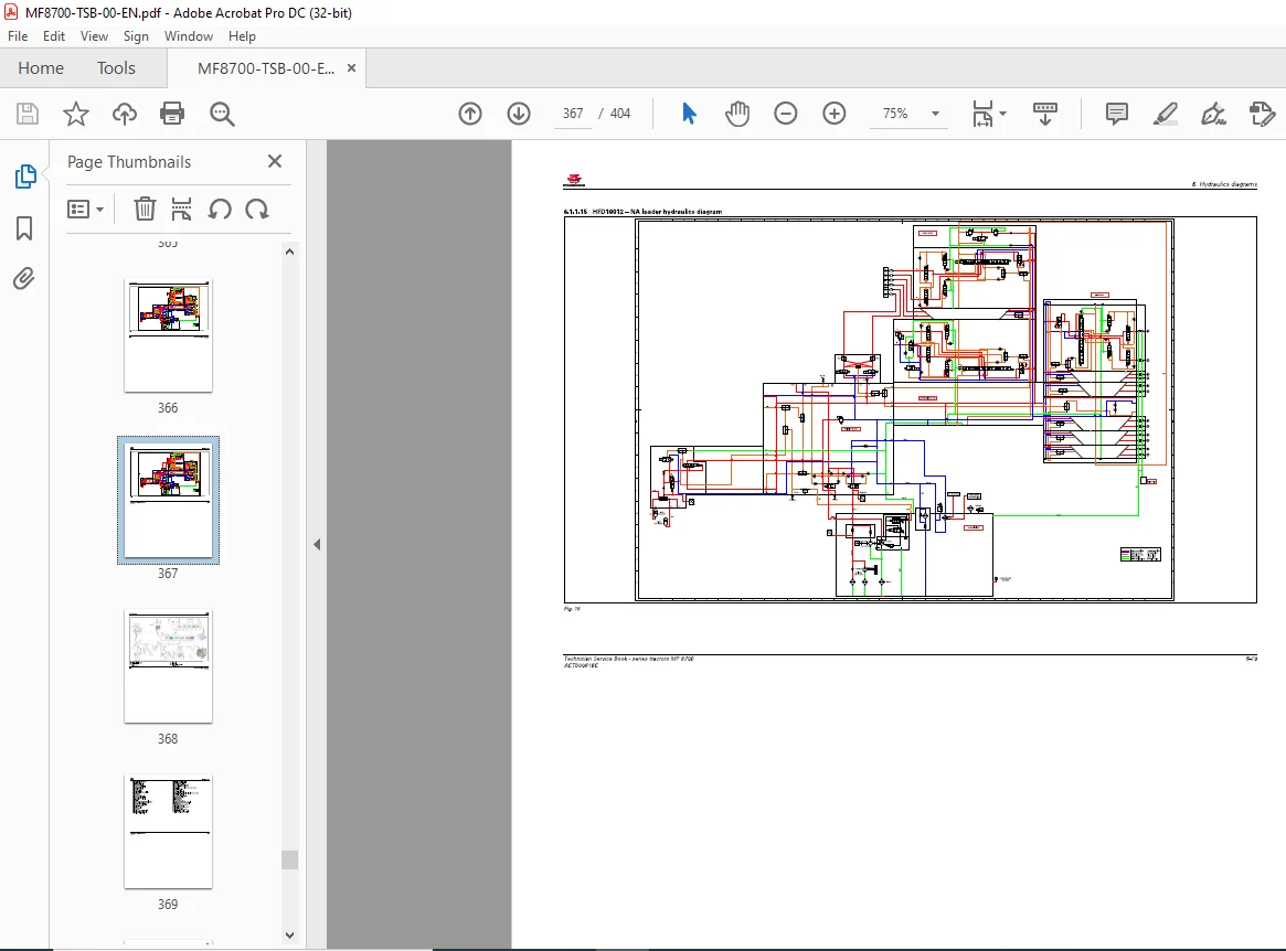
6 1 1 1 5 HF D1 001 2 -NA loader hydraulics diagram 6-1 9
6 1 1 16 Transmission hydraulics diagram 6-2 0
7 Pneumatic diagrams 7-1
7 1 Pneumatic diagrams 7-3
7 1 1 Pneumatic diagrams 7-5
7 1 1 1 PF D01 01 1 – Trailer brake pneumatic diagram 7-5
8 Adjustments, bleeding and calibrations 8-1
8 1 Bleeding 8-3
8 1 1 Bleeding the brake system 8-3
8 1 2 Bleeding the hydraulic trailer brake 8-4
8 1 3 Bleeding the pneumatic brake 8-5
8 2 Calibrations 8-6
8 2 1 Calibrating the automatic disengagement of the differential and 4-wheel drive 8-6
8 2 2 Calibration of the forward-travel lever 8-8
8 2 3 Forward speed calibration 8-1 0
8 2 4 Dyna-VT transmission calibrations: Introduction and access to calibration using the
instrument panel 8-1 0
8 2 5 Calibration of the high/low speed ranges (Hare/Tortoise) for Dyna-VT 8-1 1
8 2 6 Dyna-VT transmission calibration 8-1 2
8 2 7 Calibration of the Dyna-VT coupler function 8-1 3
8 2 8 Rear power take-off calibration for Dyna-VT 8-14
8 2 9 Front power take-off calibration for Dyna-VT 8-1 5
8 2 1 0 Dyna-VT transmission calibration error code 8-16
8 2 1 1 Calibration of the clutch pedal sensor 8-1 9
8 2 1 2 Calibration o f the throttle pedal sensor 8-1 9
8 2 1 3 Calibrating the rear linkage 8-2 0
8 2 14 Calibration of the front linkage position sensor 8-2 2
8 2 1 5 Calibrate the suspended front axle 8-2 3
8 2 16 Calibrating the suspended cab 8-2 4
8 2 17 Calibrations to be carried out using the diagnostic tool 8-2 5
8 2 17 1 Calibration of the Finger T IP controls on the armrest 8-2 5
IMAGES PREVIEW OF THE MANUAL:
PLEASE NOTE:
- This is the SAME MANUAL used by the dealerships to diagnose your vehicle
- No waiting for couriers / posts as this is a PDF manual and you can download it within 2 minutes time once you make the payment.
- Your payment is all safe and the delivery of the manual is INSTANT – You will be taken to the DOWNLOAD PAGE.
- So have no hesitations whatsoever and write to us about any queries you may have : heydownloadss @gmail.com
S.V

Kamden Finn –
Very good service