

Massey Ferguson MF 600 Series Tractor Workshop Service Manual – MF 675 MF 690 MF 698
Original price was: $42.95.$26.95Current price is: $26.95.
Complete 541-page Massey Ferguson MF 600 Series Tractor Workshop Service Manual covering MF 675, MF 690, and MF 698. Engine overhaul, hydraulics, transmission, electrical, and four-wheel-drive systems with numbered procedures and specifications.
Description
Massey Ferguson MF 600 Series Tractor Workshop Service Manual
This Massey Ferguson MF 600 Series Tractor Workshop Service Manual is the full service and repair guide for MF 675, MF 690, and MF 698 tractors. Published under Publication No. 1856 274 M1, this 541-page workshop manual gives dealers, distributors, and technicians the complete range of procedures, specifications, and technical data needed for maintenance and overhaul. Every operation carries a sequence number and is cross-referenced to illustrations that identify components and special tools, so the entire workflow remains clear and trackable.
Whether you are servicing a Perkins A4.236, A4.248, or A4.318.2 engine, adjusting the hydraulic lift system, or overhauling the four-wheel-drive front axle, this MF 600 Series workshop manual covers the job from start to finish. The manual is divided into eleven parts, each addressing a major system or assembly group.
File Details
- Manual Type: Workshop Service Manual
- Brand: Massey Ferguson
- Model: MF 600 Series (MF 675, MF 690, MF 698)
- Language: English
- Page Count: 541
- File Format: PDF
- Publication No.: 1856 274 M1
- Edition: Issue 1
Chapters Covered
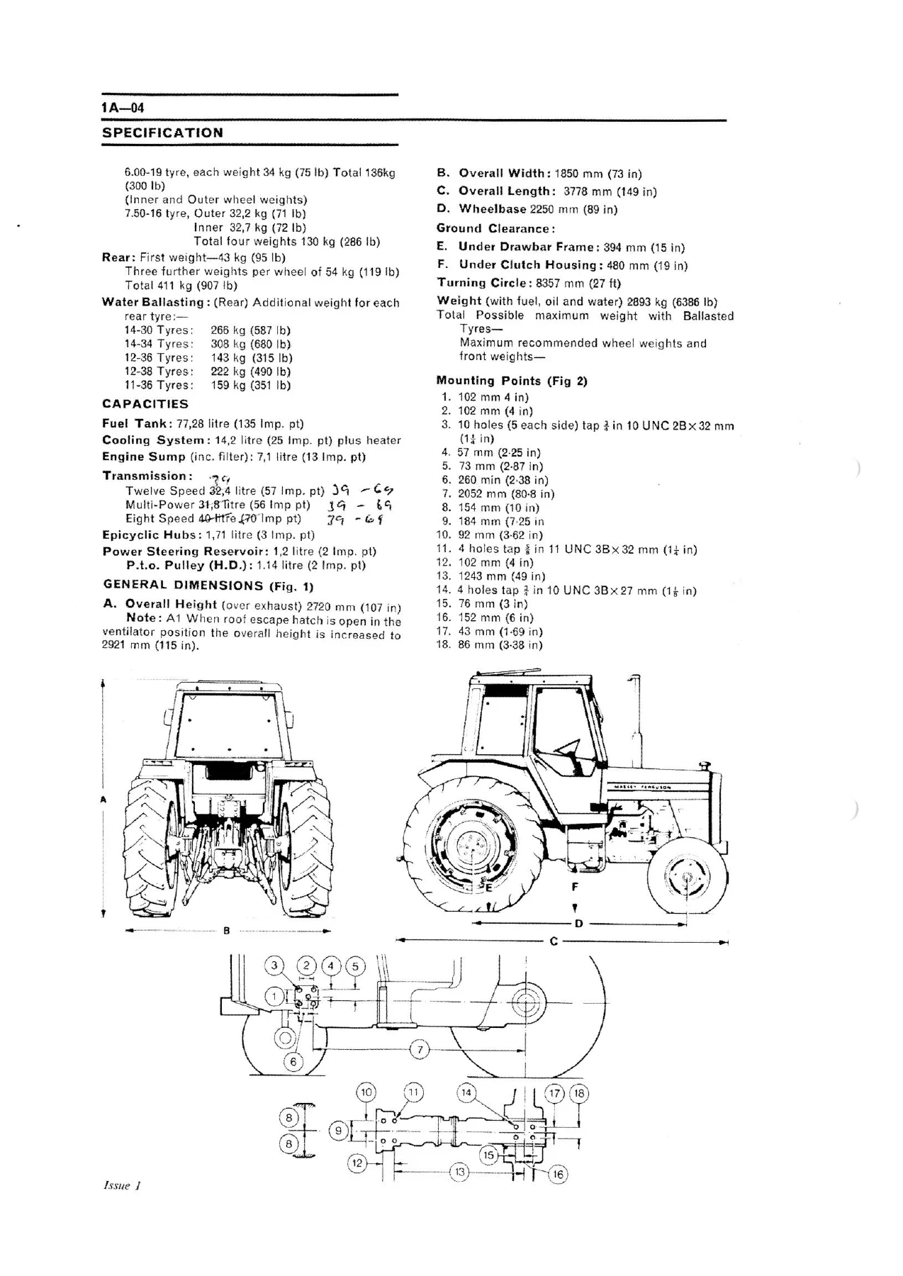
- Part 1 — General Specification, Regular Maintenance, Pre-Delivery and Installation: Introduction, Special Tools, Repairs and Replacements, Repair Time Schedule, Amendments, General Instructions, Safety, System Faults, Handling Heavy Components, Conversion Tables, Specification (engine, fuel system, electrical, cooling, transmission, PTO, hydraulics, brakes, steering, front axle, track, wheels and tyres, capacities, dimensions, mounting points), Maintenance (running-in, 50-hour and 250-hour free services, maintenance periods, approved lubricants), Pre-Delivery and Installation (pre-delivery check, storage, waterproofing)
- Part 2 — Sheet Metal, Cab and Fittings: Front Grille, Hood, Side Panel, Air Cleaner (dry and oil bath), Stone Guard, Nose, Battery Tray, Radiator Support Frame, Rear Hood Support, Rear Number Plate, Rear Centre Panel, Rear Filler Panel, Seat; Cab and Fittings covering door glass, front screen, side glass, bulkhead glass, rear window, escape hatch, heater access, door, door pockets, handles, catch, mirrors, wiper arms, footsteps, pin box, work lamp, wheel arch filler panel, door latch, air conditioning filter, sun blind, headlining, heater, B-post trim, floor mat, instrument panel, switch panel, gear lever gaiter, floor panel, heater hoses, air duct hoses, heat exchanger, blower motor, wiper motor, grab handle, rear trim panel, D-post trim, wheel arch trim, rear lower trim and window, heater control valve, heater and screen wiper switches, air-flow vents, cab roof panel, roof frame members, side window frame, rear window frame, rear lower window panel
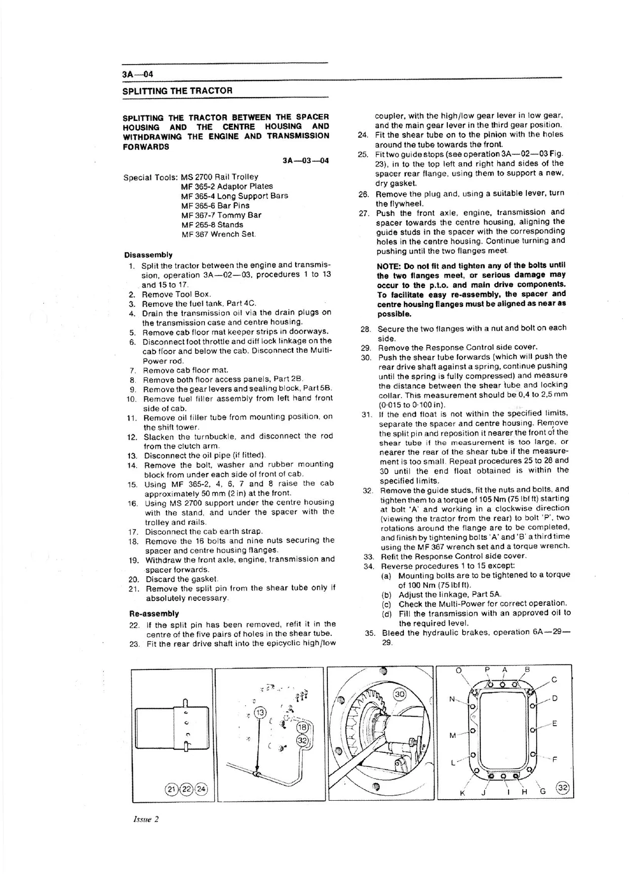
- Part 3 — Splitting the Tractor: Splitting between the front axle and the engine; splitting between the engine and the transmission; splitting between the spacer housing and the centre housing (withdrawing engine and transmission forwards, or withdrawing centre housing and rear axle rearwards)
- Part 4 — Engine, Cooling System, Fuel System and Air Cleaner: A4.236 and A4.248 Engines (fault diagnosis, rocker cover, valve tip clearance, rocker assembly, manifolds, valve springs, cylinder head, valve seat inserts, timing case, timing gears, flywheel, ring gear, crankshaft rear main oil seal, sump, oil pump, balancer unit, connecting rod big end bearings, pistons and connecting rods, cylinder liners, crankshaft thrust washers, crankshaft, camshaft, tappets, tachometer drive); A4.318.2 Engine (general, specifications, fault diagnosis, rocker cover, valve tip clearance, rocker assembly, manifolds, valve springs, cylinder head, valve seat inserts, timing case, crankshaft oil seal, idler gear, fuel pump drive gear, camshaft gear, camshaft, tappets, timing case, flywheel, ring gear, crankshaft rear oil seal, sump, oil pump, balancer unit, balancer idler gear, connecting rod big end bearings, pistons and connecting rods, cylinder liners, crankshaft thrust washers, crankshaft); Cooling System (fault diagnosis, frost precautions, radiator, thermostat, thermostat housing, water pump); Fuel System and Air Cleaner (dry element air cleaner, fuel tank stone guard, single and dual fuel tanks, fuel gauge sender unit, thermostart, fuel lift pump, fuel filter, fuel injection pump, fuel injectors, de-aeration, static fuel injection pump timing, marking angle check, foot throttle cable, hand throttle lever, throttle cross-shaft, fuel cut-off cable, foot throttle pedal, engine checking and fuel pump marking angles)
- Part 5 — Clutch (Dual and Split Torque), Transmissions: Dual Clutch (305 mm) — general, operation, fault finding, main friction disc or clutch assembly, clutch pedal adjustment, clutch assembly servicing, clutch release bearing; Split Torque Clutch (305 mm) — general, operation, fault finding, friction disc or clutch assembly, clutch pedal adjustment, clutch assembly servicing, clutch release bearing
- Part 6 — Power Take Off: PTO shaft oil seal, PTO shaft, PTO shaft rear bearing, needle bearing, ground speed gear/bush/pinion shaft gear assembly, needle bearings and reduction gears, PTO side cover; Independent Power Take Off — IPTO clutch unit, clutch assembly servicing, IPTO control valve, IPTO brake unit, IPTO hydraulic test
- Part 7 — Front Axle, Steering, Wheels and Tyres: Front axle (general, front track adjustment, toe-in, front hub servicing, spindle shaft, spindle housing, beam assembly, axle support casting for 2WD and 4WD); Steering (system bleeding, steering pump, steering wheel, steering column, hydrostatic steering hand pump, hydrostatic steering cylinder, steering oil cooler, pipes and hoses, power steering ram, steering ram setting, track rod); Wheels and Tyres (inner tube, tyres, fault finding chart)
- Part 8 — Hydraulic System, Auxiliary Hydraulics, Drawbar and Linkage: Hydraulic System (operation including draft control, position control, response control, pressure control; control spring assembly; hydraulic lift cover; ram cylinder; hydraulic linkage; quadrant control support assembly; hydraulic quadrant assembly; hydraulic adjustments external and internal; hydraulic pump; control valve; pressure control valve; transmission and hydraulic pump filter; strainer housing and response control; vacuum switch; spool valve unit; spool block; trailer braking spool valve; selector valve); Auxiliary Hydraulics (oil cooler, transmission oil filter, auxiliary or Multi-Power/IPTO pump, plated drive, pressure maintaining valve, hydraulic testing including auxiliary relief valve, flow test, Multi-Power pressure test, relief valve test, flow test, IPTO pressure test, pressure maintaining valve check); Drawbar and Linkage (top link, lower links, lift rods, control beam, hook-type lower links, hook-type top link, right hand lift rod and levelling box, left hand lift rod, rear mounted position control lever, lift arm, link arm, check chains, stabiliser chains, levelling box, remote levelling lever assembly, pickup hitch)
- Part 9 — Electrical System and Equipment: Wiring diagram, servicing the electrical system, battery, alternator, starter motor, starter switch, fuel cut-off control, flashing indicator and headlight flash switch, cigar lighter, tractormeter, fuel and temperature gauge, light switch, warning light bulbs and lens, hazard warning light switch, fuse box, neutral safety start switch, engine oil pressure warning light switch, temperature gauge sender unit, Multi-Power oil pressure warning light switch, thermostart, interior light and bulb, blower switch, windscreen wiper and washer switches, headlight bulb and headlight, side light/flashing indicator bulb, tail/brake/flashing indicator bulb, plough light bulb, blower motor, wiper motor, windscreen washer electric pump, headlight wiring connector, handbrake warning light switch, indicator flasher unit, front harness, instrument panel harness, cab and rear harness, cab roof harness, windscreen washer bottle assembly
- Part 10 — Accessories: Stabilisers, stabiliser extension kit, hydraulic assistor ram, drawbar and stays, pressure control coupler, safety release ball, PTO belt pulley assembly, PTO belt pulley guard assembly, front mounted weight frame, wheel ballast weights, front wheel weights, rear wheel weights, fire extinguisher mounting point
- Part 11 — Special Models (Four Wheel Drive): Category III Front Axle (planetary carrier, ring gear and reduction unit hub, wheel spindle/half shaft/universal joint assembly, front axle pivot housing, front axle removal and refitment, rear support spacer, front support, rear support/input housing, differential assembly, differential bearings, crownwheel bearing adjustment and pinion teeth backlash, crownwheel, bevel drive pinion, transfer gear box, hydraulic clutch/bearings/output shaft, control valve); Category II Front Axle (planetary carrier, ring gear and reduction unit hub, wheel spindle/bearings/oil seals, front axle pivot housing, half shaft and universal joint assembly, rear support/input housing, differential assembly, differential bearings, crownwheel bearing adjustment and pinion teeth backlash, differential servicing, crownwheel, bevel drive pinion assembly, bevel drive pinion axial position)
The scope of this Massey Ferguson MF 600 Series workshop manual extends well beyond routine maintenance. Each of the eleven parts is built around numbered operations that guide you through disassembly, inspection, repair, and reassembly in the correct sequence. Torque values, clearance limits, and adjustment procedures appear at the point of use, and special tool numbers are called out wherever they are required. The engine section alone covers three Perkins power units in detail, with full specifications, service limits, and step-by-step overhaul procedures for cylinder heads, pistons, liners, crankshafts, and balancer units. The hydraulic section explains the Ferguson system from first principles — draft control, position control, response control, and pressure control — and then takes you through pump servicing, lift cover removal, ram cylinder resealing, and the internal and external adjustment procedures that keep the linkage operating correctly.
IMAGES PREVIEW
For tractors equipped with four-wheel drive, Part 11 addresses the Category III and Category II front axles, including planetary reduction units, differential overhaul, crownwheel and pinion backlash setting, and the hydraulic clutch in the transfer gear box. The electrical section provides a full wiring diagram for the negative-earth system along with component-level test procedures for the alternator, battery, starter motor, and every switch and gauge on the tractor. The cab and sheet metal section covers everything from the front grille to the rear window frame, with removal and refitment procedures for panels, glass, seating, heater components, and trim.
What This Manual Enables You to Do
With this Massey Ferguson MF 600 Series Tractor Workshop Service Manual on hand, you can carry out engine overhauls, clutch replacement, transmission splitting, hydraulic pump servicing, brake adjustment, steering system repair, and electrical fault diagnosis — all to the specifications and procedures used by the manufacturer. The manual gives you the correct torque figures, end-float limits, shim thicknesses, and adjustment sequences so that each repair is done right the first time. Instead of guessing at clearances or improvising with generic advice, you follow the same numbered operations that a dealer technician would use.
This MF 600 Series repair manual is delivered as an instant PDF download. There is no shipping wait and no physical book to keep track of. The file can be stored on a computer, tablet, or smartphone, and individual pages or sections can be printed for use in the workshop. Whether you are a professional mechanic, a farm owner maintaining your own equipment, or a collector restoring an MF 675, MF 690, or MF 698, this Massey Ferguson workshop manual provides the technical depth needed to keep the tractor running properly.
Reviews
There are no reviews yet.