
Massey Ferguson MF660 MF660/4 MF680/4 Parts Catalogue CPE660 E01 – PDF Download
Original price was: $74.95.$49.95Current price is: $49.95.
575-page Massey Ferguson illustrated parts catalogue covering MF660, MF660/4 and MF680/4 applications, with extensive exploded parts diagrams for the engine, clutch, 12-speed transmission, rear axle and differential, hydraulic equipment, PTO, front axle, steering, brakes, electrical system, operator platform, cab, wheels, weights and accessory equipment. Includes English, Portuguese and Spanish parts descriptions and part numbers throughout.
Description
Massey Ferguson MF660, MF660/4 & MF680/4 Illustrated Parts Catalogue
This Massey Ferguson MF660 MF660/4 MF680/4 Parts Catalogue CPE660 E01 is a substantial illustrated component reference built around exploded views, item numbers, quantities, part numbers and multilingual component descriptions. Across 575 PDF pages it follows the tractor through the engine, clutch and transmission, rear axle and differential, hydraulic and PTO assemblies, front axle, steering and braking equipment, electrical components, operator controls, cab equipment, wheels, weights and additional accessories. It is especially useful when a repair has progressed beyond identifying the failed assembly and you need to determine exactly which shaft, bearing, seal, gear, bracket, hose, fastener, housing or related component belongs in that assembly.
The catalogue repeatedly identifies applications for MF660, MF660/4 and MF680/4, with model and serial break references printed alongside many individual parts arrangements. The engine material includes the 1006-6t designation, while the transmission section contains detailed 12-speed Syncromesh layouts, PTO-related arrangements and numerous shim, bearing, shaft and gear listings.
File Details
- Manual type: Parts Catalogue
- Brand: Massey Ferguson
- Models referenced: MF660, MF660/4, MF680/4
- Language: English, Portuguese, Spanish
- Page count: 575 pages
- File format: PDF
- Document identification: CPE660 E01 (0) 09/01
How the Catalogue Is Laid Out
Each parts plate combines an exploded drawing with numbered callouts and a matching component list. The listings show the applicable part number, quantity and component name, allowing the drawing and parts list to be used together rather than relying on description alone. Many plates also carry applicability notes, reference symbols and model or serial break information. This matters on assemblies such as the transmission, hydraulic equipment and electrical system where visually similar parts may change between configurations.
The component descriptions are presented in Portuguese, English and Spanish through the catalogue. Typical entries include items such as cylinder blocks, liners, crankshafts, pistons, connecting rods, oil pumps, cylinder heads, rocker shafts, camshafts, injection equipment, clutch components, transmission gears, shafts, bearings, hydraulic valves, steering components, wiring harnesses, switches, lamps and cab hardware.
Chapters Covered
- Engine
- Clutch
- 12 Speed Transmission
- Rear Axle And Diferential
- Hydraulic Arms
- IPTO
- Front Axle
- Steering / hydraulic and brake equipment
- Instrument Panel / Electric System
- Decal / Emblems
- Operator Plataform
- Cab
- Bracket And Front Wheight / Wheels
- Tools and additional equipment
Engine
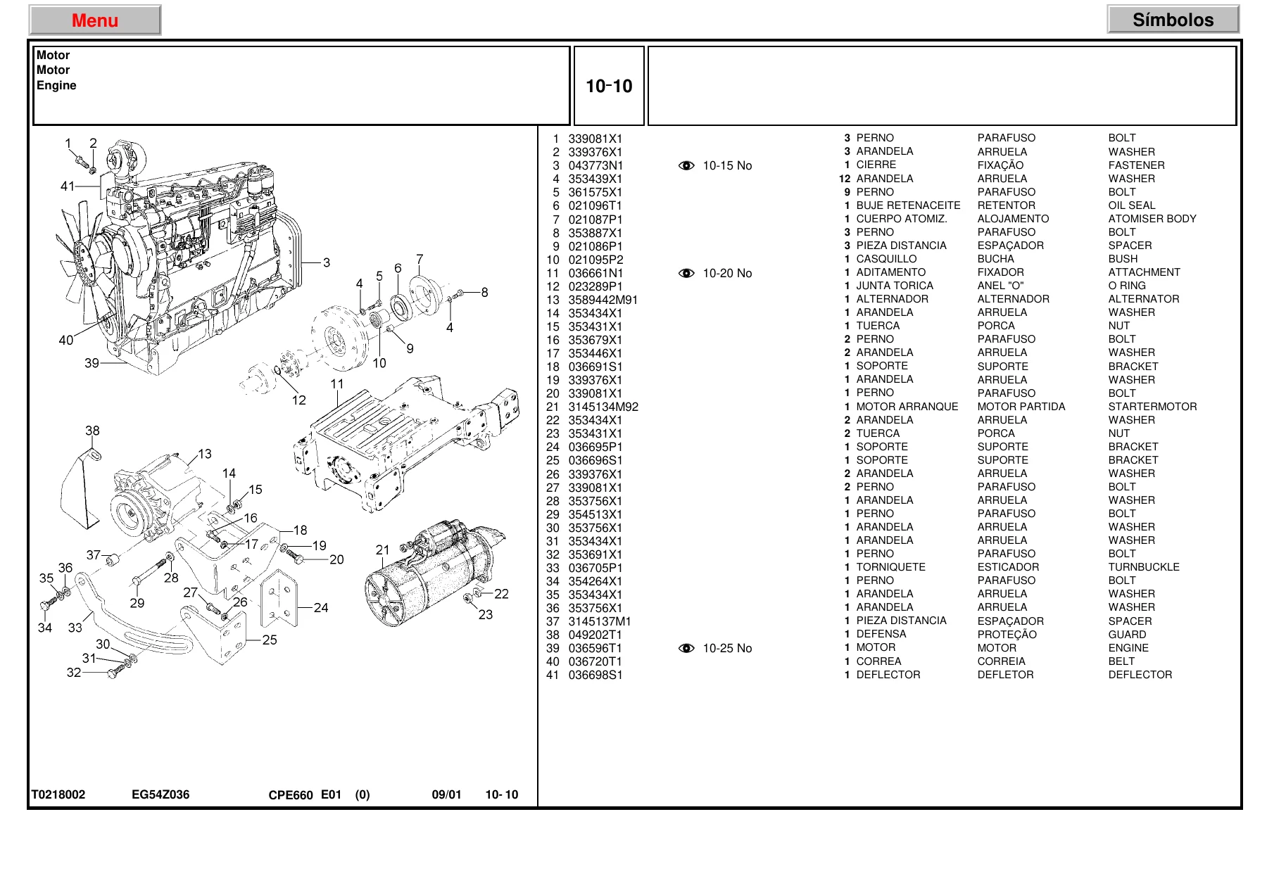
The engine material is one of the largest portions of the catalogue. It begins with complete engine installation and fastening arrangements and then works through detailed internal and external assemblies. Exploded plates identify the cylinder block, liners, crankshaft and bearing kits, pistons and connecting rods, lubricating oil pump, cylinder head, valves and rocker shafts, crankshaft oil seal, camshaft, timing case and idler gears. Further plates cover the oil sump, crankshaft pulley, oil filter and oil cooler, cylinder head covers, thermostat and housing, induction and exhaust manifolds, fuel injection pump, low-pressure fuel pump, injection pipes and atomisers, engine breather, water pump, turbocharger installation, air cleaner, cooling system, radiator, fuel tanks and flywheel-related components.
The engine pages also distinguish component options and service-part alternatives with reference notes, symbols and part-number substitutions. The 1006-6t engine designation appears within this section, and the drawings include both complete assembly views and detailed internal component breakdowns. For engine work, this makes the catalogue valuable not only for identifying a major assembly but for tracing the smaller seals, washers, bushes, gaskets, studs, pipes and fasteners associated with it.
Clutch
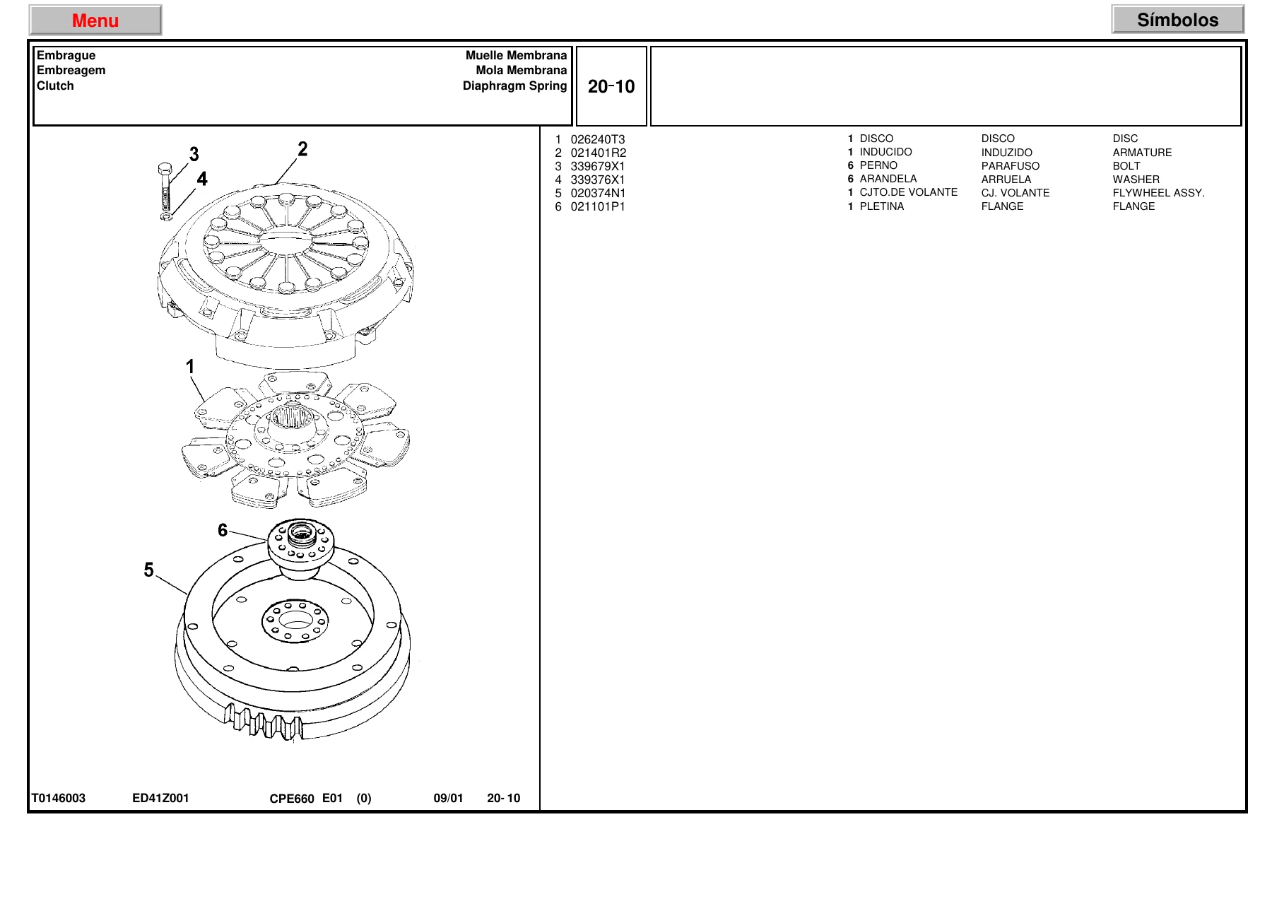
The clutch section illustrates the diaphragm-spring clutch and double-disc arrangements with the flywheel assembly, clutch discs, flange and attaching hardware. Exploded views separate the front and rear discs where applicable so the individual components can be matched to their listed part numbers instead of treating the clutch as a single unit.
12 Speed Transmission
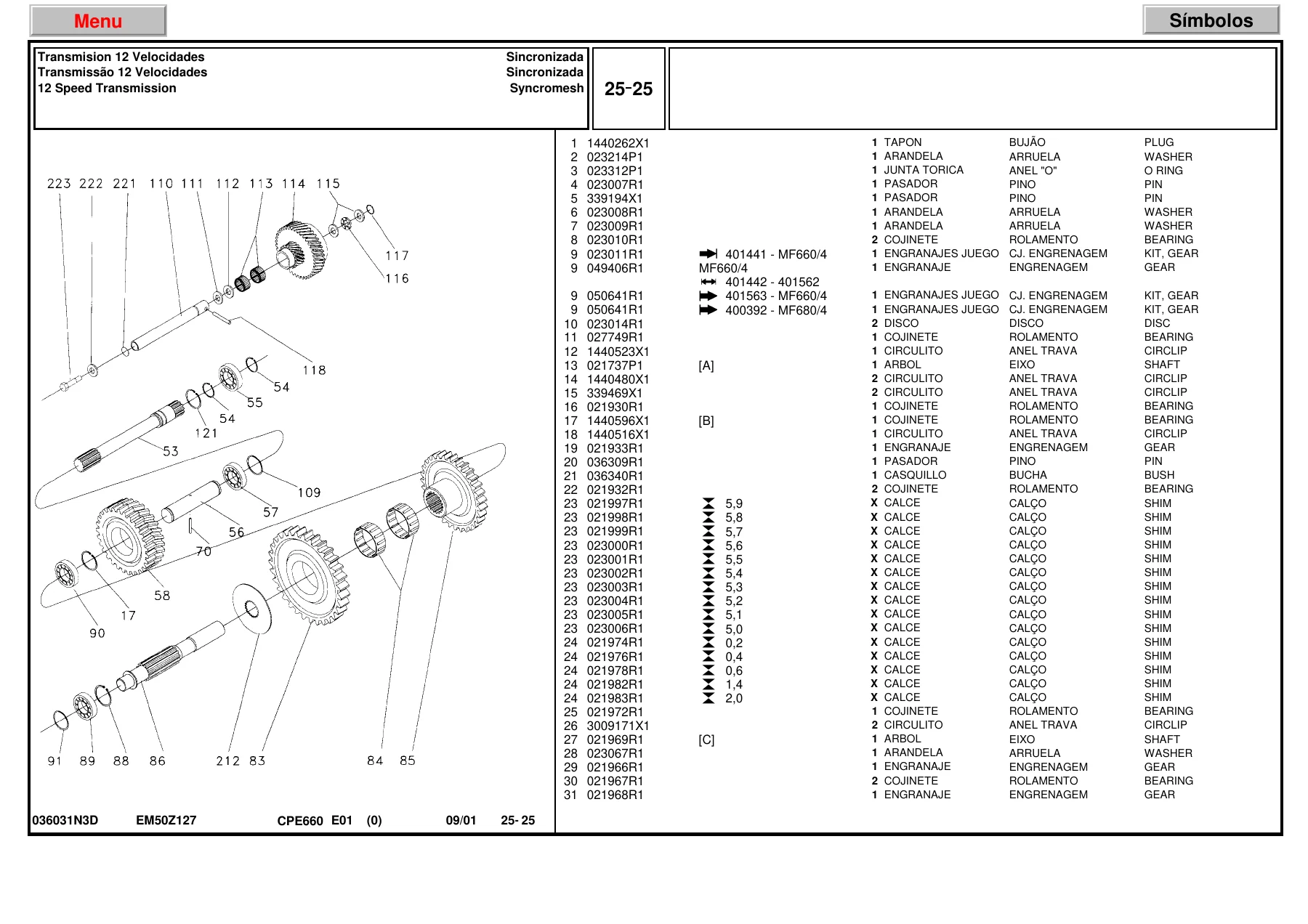
The 12-speed transmission coverage is exceptionally detailed. The catalogue identifies the transmission housing, shafts and forks, selectors, gears, bearings, circlips, sleeves, hubs, bushes, springs, pins and extensive shim selections. Syncromesh arrangements are shown in multiple exploded plates, including configurations associated with PTO operation and different model or serial references. Several pages provide dimensional shim options directly against individual part numbers, useful when identifying the exact catalogue item used in a particular shaft or gear stack.
Transmission plates also contain model references for MF660, MF660/4 and MF680/4, including application breakpoints printed within the drawings. That makes this Massey Ferguson 12-speed transmission parts catalogue particularly useful when a technician is comparing two assemblies that appear similar but use different gears, bearings or adjustment pieces.
Rear Axle And Diferential
The rear axle and differential section continues the exploded-parts approach through transmission fastening, differential and rear axle housings, shafts, gears, bearings, seals, hubs and related mechanisms. Individual components are numbered against the drawing so internal pieces can be identified in their assembled relationship rather than from a name alone. The section also includes the connecting hardware, covers, plugs, sleeves, forks and cylinders associated with the rear driveline structure.
Hydraulic Arms and Linkage
Hydraulic lift-related plates cover the master beam and drawbar, hydraulic arms and their associated linkage. Different arrangements are shown with brackets, pins, shafts, arms, rods, joints and mounting hardware. Because the diagrams preserve the relationship between small linkage pieces and the main lift components, they are useful when dismantling an existing linkage or checking what is missing from an incomplete assembly.
IPTO and PTO Components
The catalogue contains dedicated IPTO material, including 540/1000 rpm arrangements and associated shafts, gears, bearings, housings, discs, sleeves and operating components. Several transmission pages also identify power take-off related components, so PTO parts can be traced both in their dedicated section and where they interface with the transmission.
Front Axle
The front axle coverage includes several ZF APL359 arrangements and clearly labelled Front Axle plates. Exploded drawings break the axle down into housings, shafts, bearings, seals, gears, hubs and steering-related mechanical parts. Where different drive or configuration variants are used, the catalogue prints the relevant references alongside the component listings.
Steering, Brakes and Hydraulic Control
The steering material begins with the steering column and expands into steering linkage, hydraulic steering components, valves, pumps, hoses, pipes and related fittings. The same broad section of the catalogue also contains brake and hydraulic-control equipment, including master-cylinder and valve assemblies, remote-control hydraulic components and oil radiator arrangements. These pages are particularly useful for following hydraulic lines and fittings through a system because the hose, pipe, connection, clamp and valve positions are illustrated rather than supplied only as part numbers.
Instrument Panel and Electric System
The electrical section covers the instrument panel and a wide range of harnesses, switches, senders, lamps, battery components and electrical fittings. Headlamps, tail lights and auxiliary lighting receive their own illustrated plates, while other pages show the wiring-associated hardware used with engine and hydraulic functions. Individual harnesses, grommets, connectors, brackets, bulbs and switches are separately identified, which helps when the required replacement is only one part of a larger electrical assembly.
Decals, Emblems and Identification
Dedicated decal and emblem pages identify warning, operating and identification labels. The catalogue distinguishes language versions and includes references for items such as model and serial identification, PTO drive, 4WD, battery, fuel filter, engine information and operating warnings. Some decal listings also identify English, Spanish, Portuguese and French versions as separate catalogue items.
Operator Plataform, Controls and Seat
The operator area is broken down into the platform structure, pedals, levers, control linkages, seat components, brackets, covers and surrounding hardware. Remote-control levers and other operating controls are shown in exploded form, allowing small bushes, pins, springs, knobs, shafts and fasteners to be identified individually. This section is useful when restoring worn controls where several inexpensive hardware pieces may be responsible for excess movement or incomplete operation.
Cab and Interior Equipment
Cab coverage extends through the cab structure, supports, roof, interior finish, rear lighting and associated trim and mounting hardware. The parts plates identify panels, mouldings, foam, seals, brackets, switches, washers, screws and other pieces that can be difficult to identify once the interior has been removed. The section preserves the original exploded relationships between the larger cab pieces and their smaller attachment components.
Weights, Wheels and Exterior Hardware
The later catalogue sections include the front weight bracket and weights plus wheel arrangements, including rear-wheel plates. Fasteners, discs, rims and associated mounting parts are individually listed. These illustrations are useful where the tractor has been altered over time and the current wheel or weight arrangement needs to be compared against the catalogue configuration.
Tools and Additional Equipment
The final section includes the sedimenter and fuel-filter kit, tool box, tool kit, greaser, wheel spanner, lighting equipment, protector-related items and starting heater. These pages complete the catalogue with accessories and equipment that sit outside the major tractor assemblies but still carry dedicated Massey Ferguson part references.
A Practical Parts Reference for Major Repairs and Detailed Reassembly
The real strength of this Massey Ferguson MF660 / MF660/4 / MF680/4 parts manual is the depth of its exploded component coverage. It can support engine strip-down work, clutch and transmission rebuilding, rear axle and differential repairs, hydraulic and PTO servicing, front axle work, steering and braking repairs, electrical troubleshooting that requires correct component identification, cab restoration and replacement of controls, wheels, weights or accessories. Instead of ordering from a verbal description, you can work from the illustrated position of the component and the corresponding catalogue part number.
For older machinery, that level of identification matters. A bearing, seal, shim, hose or bracket may look close to another part but belong to a different serial or assembly configuration. The catalogue’s exploded views, application notes, model references and part-number listings give you a much stronger basis for matching the part actually used on the machine before ordering or reassembling it.
Instant PDF delivery means there is no printed book to ship and no postal delay. After purchase, the Massey Ferguson MF660 MF660/4 MF680/4 Parts Catalogue can be opened on a computer, tablet or phone and printed when you need pages beside the machine. Whether you are identifying one replacement component or working through a major transmission, engine, axle or hydraulic overhaul, this 575-page illustrated catalogue puts the original parts breakdowns and component references in one immediately accessible file.
IMAGES PREVIEW
Reviews
There are no reviews yet.