
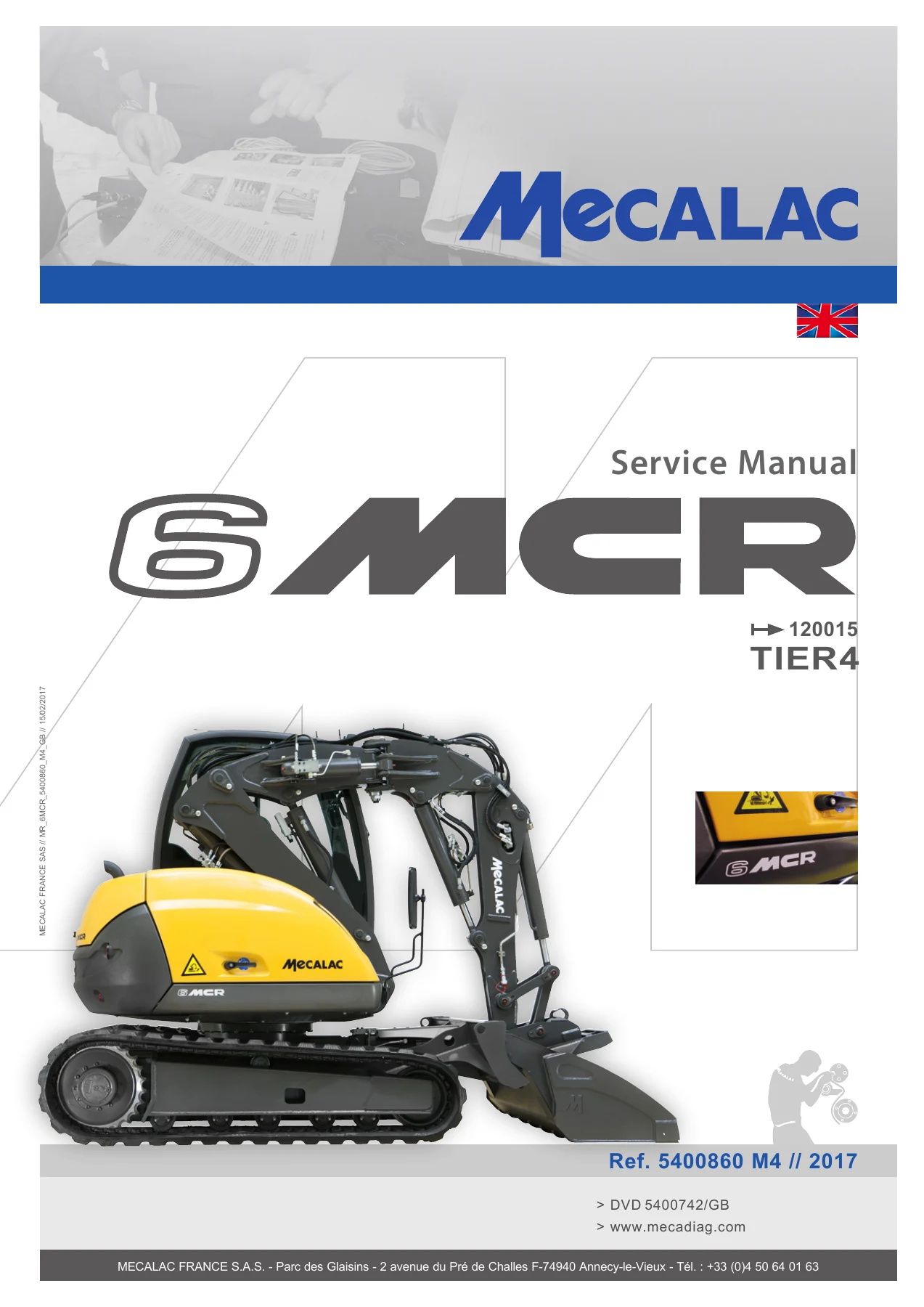
Mecalac 6MCR Tier4 Service Manual 2017 – 6MCR Excavator Full Workshop PDF
Original price was: $52.95.$34.95Current price is: $34.95.
Complete Mecalac 6MCR Tier4 service manual (5400860 M4, 2017) covering engine, hydraulics, electrics, CAN network, fault codes, adjustment procedures and maintenance for the 6MCR Tier4 excavator. Instant PDF download.
Description
Mecalac 6MCR Tier4 Service Manual – Complete Workshop Documentation (2017)
This is the complete Mecalac 6MCR Tier4 service manual, issued under document reference 5400860 M4 for the 2017 model year and covering machine reference 120015. It is the full workshop-level publication for the 6MCR Tier4 compact excavator, written for professional technicians and serious owners who need to maintain, diagnose, repair and adjust the machine to factory specification. Both the electrical and hydraulic systems are documented in exceptional detail, alongside the engine, mechanical assemblies, structural components and safety procedures.
File Details
- Manual type: Service Manual (Workshop Manual)
- Brand: Mecalac
- Model: 6MCR Tier4
- Machine reference: 120015
- Document reference: 5400860 M4
- Year: 2017
- Language: English
- Page count: 180 pages
- Format: PDF (instant download)
Chapters Covered
- 01. Safety instructions
- 02. Description of the machine
- 03. Technical characteristics
- 04. Towing
- 05. Table of stability loads in kg
- 06. Table of recommended lubricants
- 07. Inspection and maintenance table
- 08. Tightening torques
- 09. Tooling
- 10. Parts list of the electric diagram
- 11. Control panel descriptive
- 12. Operation and use (joystick)
- 13. Location of the electric components
- 14. Location harness connector
- 15. CAN network
- 16. Solenoid valves operation logic diagram
- 17. Layout of electrical harnesses
- 18. Fault codes
- 19. Location of the hydraulic components
- 20. Parts list of the hydraulic diagram
- 21. Connection of hydraulic components
- 22. The adjustment procedures
- 23. Inspection sheet
Safety Instructions & Machine Description
Chapter 01 opens with the safety instructions that govern every procedure in the manual, including the specific precautions for using the Mecadiag diagnostic tool, downloading software, remote coding, settings and actuator tests. Chapter 02 describes the machine architecture: the rigid central chassis with multi-roller tracks, the hydrostatic transmission, the turret with its internally toothed slewing ring and full 360° rotation, the sound-insulated cab, and the four-element equipment (boom, intermediate boom, coupling and dipper).
Technical Characteristics & Capacities
Chapter 03 is the reference chapter for the 6MCR Tier4‘s specifications. It documents the Tier4 DEUTZ TD 2.9 L4 (Phase IIIB) four-cylinder turbo diesel, rated at 55.4 kW at 2,300 rpm with a maximum net torque of 260 N.m at 1,800 rpm (300 N.m with the DPF version). Capacities include a 60-litre hydraulic oil tank, 90-litre total hydraulic circuit, 70-litre fuel tank, 8-litre engine sump and 18-litre cooling system. The electrical system is documented as 12 V with a 175 Ah battery, 2.6 kW starter and 95 A alternator. Cylinder bore, rod and stroke dimensions are tabulated for the boom, adjustable boom, offset ram, dipper stick, bucket ram and blade cylinders.
Towing, Stability Loads & Lubricants
Chapter 04 covers the transmission towing procedure in step-by-step detail, including removal of the gear motor cap, satellite gear and pin to allow freewheeling. Chapter 05 provides the stability load tables in kilograms for longitudinal and transverse working positions, with blade, along with the deductions for handling plates, hooks, quick couplers and buckets. Chapter 06 is the recommended lubricants table, giving the approved oils and greases by system (engine, hydraulic circuit, travelling motor-reduction units, general lubrication, coolant and air conditioning) with temperature limits and viscosity grades.
Inspection, Maintenance & Torques
Chapter 07 is the inspection and maintenance table, arranged by interval from 8 hours up to 3,000 hours, covering general checks, fuel system, water cooling system, engine, air filter, battery, tracks and travel reduction gear, hydraulic circuit, slewing motor, lubrication, and heating/air conditioning. Compulsory warranty inspections are marked. Chapter 08 provides the standard tightening torques for classes 8.8, 10.9 and 12.9, followed by the specific tightening torques for the attachment pump, coupling flange, slewing motor, compressor, auxiliary pump, equipment, counterweight, slewing ring, silentbloc engine and cab mounts, and motor-reduction units, including Loctite requirements. Chapter 09 lists the special tooling: the MX12 test pencil (Ref. 6160076), the Mecadiag diagnostic tool (Ref. 6160057) and the various connector extraction tools.
Electric System (Chapters 10-18)
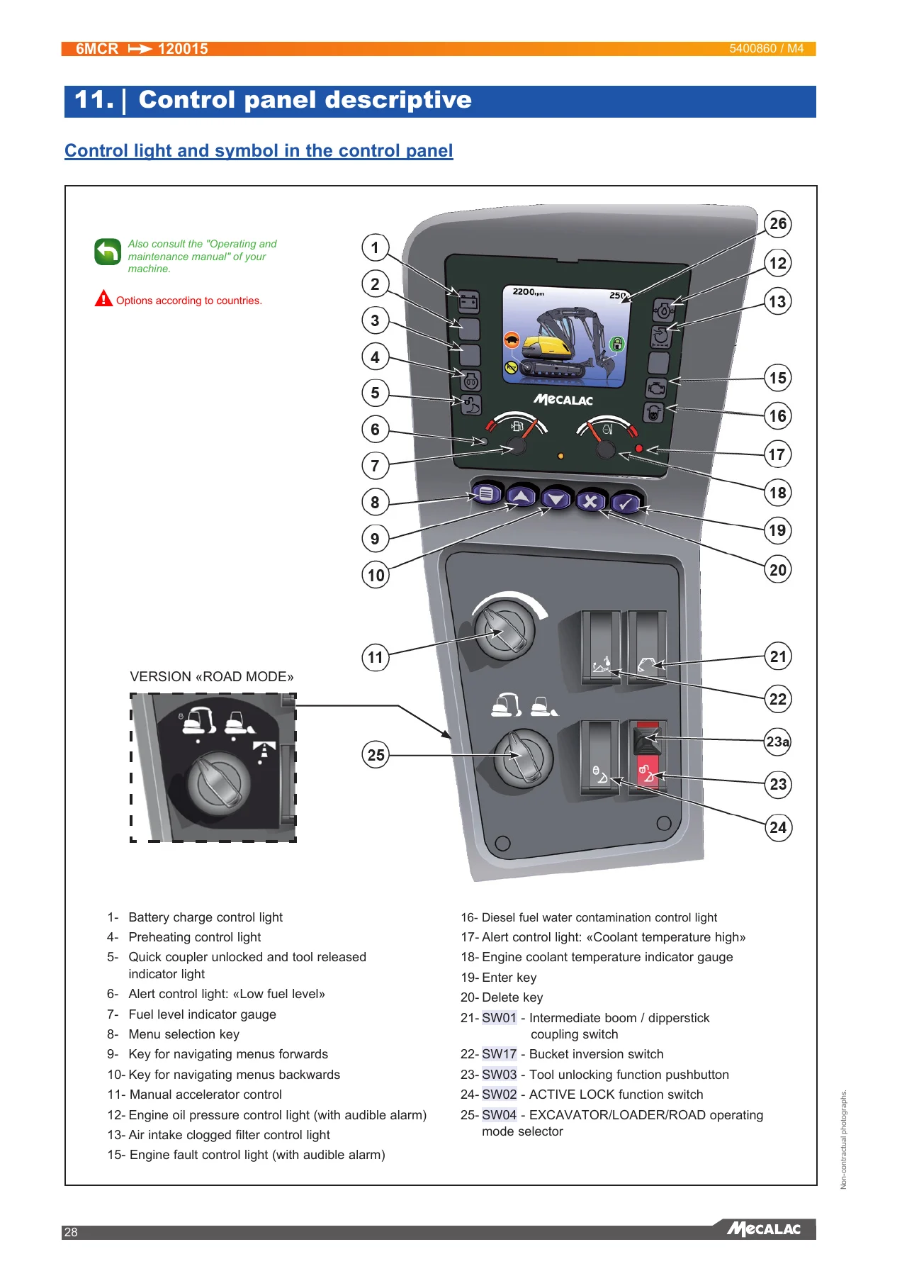
The electrical section is the largest single block in the manual. Chapter 10 is the complete parts list of the electric diagram, listing every fuse, relay, sensor, solenoid valve, switch, motor, light and connector by code, with fuse ratings and functions. Chapter 11 describes the control panel and every indicator light and symbol. Chapter 12 explains the left and right joystick functions in both EXCAVATOR and LOADER modes. Chapter 13 covers the location of the electric components in real situations, with the circuit marking convention, the solenoid valves, and the relay plate U15 layout. Chapter 14 provides the full pinout for the harness connectors: U01/RC30, U05/EMR4, engine Deutz U17, U06 control panel and the U15 relay plate sockets. Chapter 15 documents the CAN network topology, including the CAN-H and CAN-L lines, the 120 ohm termination resistors and the diagnostic socket pinout. Chapter 16 is the solenoid valves operation logic diagram, showing the energisation state of every valve in each machine function. Chapter 17 lays out the full electrical harness routing and harness-by-harness wiring tables. Chapter 18 explains how to read fault codes from the dashboard and provides the fault code descriptions.
Hydraulic System (Chapters 19-23)
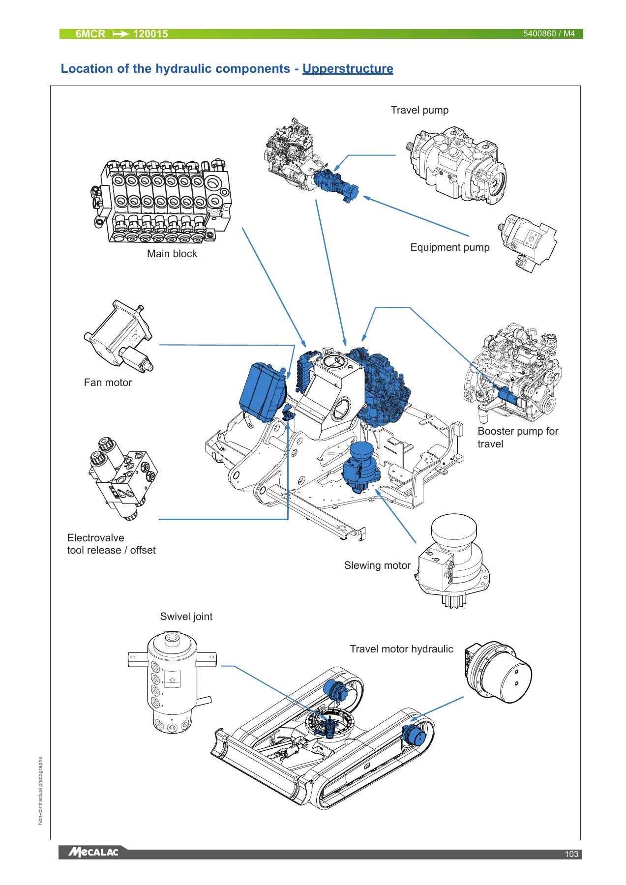
The hydraulic section begins in Chapter 19 with the location of the hydraulic components on the machine, the uppertructure and the cab floor/driver station. Chapter 20 is the parts list of the hydraulic diagram, and Chapter 21 covers the connection of the hydraulic components function by function: travelling/slewing, load sensing and fan/turret supply and return, spool valve, offset ram, equipment without valve, equipment with safety valves, rotating clam-shell bucket, quick coupling (Mecalac CONNECT and Volvo), accessories, blade and hammer return. Chapter 22 is the adjustment procedure chapter, covering engine revs control (minimum, excavator maximum, loader maximum), control of pilot pressure, fan adjustment, maximum pressure in the equipment pump, stand-by pressure, delta P adjustment (with and without flowmeter), power regulation, choke valve auxiliary function, slewing delta P, pilot pressure for transmission and high pressure transmission pump. Chapter 23 is the inspection sheet for recording all the values noted or adjusted during a service.
Why This Manual Matters for the 6MCR Tier4
The Mecalac 6MCR Tier4 is not a simple machine. It combines a Senso Drive closed circuit hydrostatic transmission with a load-sensing attachment and slewing circuit and an independent fan supply circuit, all managed by CAN-bus electronics and a DEUTZ EMR4 engine computer. Getting the pressures, delta P values and valve logic right is the difference between a machine that digs cleanly and travels smoothly and one that overheats, loses power or throws fault codes. This 6MCR Tier4 service manual gives you the exact figures: 280 bar maximum working pressure in the equipment pump, 330 bar maximum in the transmission, 35 bar assistance pressure, 30 bar stand-by pressure, 15 bar delta P and 240 bar LS pressure for slewing.
Beyond the numbers, the manual shows you how to reach those numbers. The adjustment procedures in Chapter 22 are written for the workshop floor, with the specific tools required, the engine speed and oil temperature conditions, the reference points on the pump and main block, and the expected reading for each step. The electrical section gives you the fault code list, the CAN network topology and the connector pinouts you need to trace a wiring fault without guessing. The hydraulic section shows you the routing of every hose and the function of every valve, so you can diagnose a slow function, a drifting cylinder or a weak travel circuit with a logical approach rather than by swapping parts.
IMAGES PREVIEW
Instant PDF Delivery
The Mecalac 6MCR Tier4 service manual is delivered as an instant PDF download after payment. There is no shipping, no waiting for a disc, and no risk of a damaged paper copy. You can open it on a workshop laptop, a tablet on the machine, or a phone in the cab, and you can print the pages you need for the job at hand. The PDF format also means you can search for a model code, a torque value or a fault code in seconds, which is exactly what you want when the machine is down and the customer is waiting.
Reviews
There are no reviews yet.