Description
Mercury 40/50hp Two Stroke Outboards Service Manual – 90-8M0228641
This is the complete service manual for Mercury Marine 40hp and 50hp two-stroke outboard engines, published under document number 90-8M0228641 with a May 2024 edition date. It is the same reference material used in professional marine workshops, covering the full 3-cylinder 697cc two-stroke platform across tiller handle, remote control, manual start, electric start, oil-injected and premix configurations. Every major system is documented with step-by-step procedures, exploded diagrams, wiring schematics and factory specification tables.
File Details
- Manual type: Service Manual
- Brand: Mercury Marine
- Document number: 90-8M0228641
- Edition: May 2024
- Language: English
- Page count: Approximately 460 pages
- File format: PDF (instant download)
- Models covered: 40MH, 50MH, 40EH, 50EH, 40EHO, 50EHO, 40EO, 50EO, 40EHPT, 50EHPT, 40EPTO, 50EPTO, W50MH, W50EHPT, W50EO
- Engine platform: 3-cylinder, 697cc, two-stroke, through-hub exhaust
Chapters Covered
- 1 – Important Information
- A – Specifications (master specs, carburetor, powerhead, cooling, ignition, charging/starting, gearcase, power trim)
- B – Maintenance (inspection schedule, flushing, cowl removal, battery, fuel system, anodes, propeller, spark plugs, lubrication points, gear oil, power trim fluid, submerged outboard, storage)
- C – General Information (serial number location, model year codes, lanyard stop switch, performance factors, trim tab, compression check, painting, decals)
- D – Outboard Installation (mounting hardware, transom mounting, remote control devices, cable adapters, electrical harnesses, battery installation, propeller selection, break-in procedure, tune-up)
- 2 – Electrical
- A – Ignition (specifications, components, magneto, CD unit, ignition coil, key switch, wire color codes, troubleshooting, spark test, stop circuit test, exciter coil test, pulser coil test, CD output test, ignition coil tests, output tests, RPM limitation tests, flywheel removal/inspection/installation, coil plate assembly, exciter coil, ignition coil, CD unit)
- B – Charging and Starting System (specifications, battery, alternator coil test, rectifier/regulator diode test, rectifier/regulator removal/installation, alternator coil removal/installation, starting system description, starter circuit tests, starter solenoid test, main key switch test, neutral start switch test, choke solenoid test, starter motor tests, removal, disassembly, brush assembly testing, installation)
- C – Timing, Synchronizing, and Adjusting (ignition specifications, throttle linkage components, ignition timing adjustment, carburetor synchronization, oil pump aperture adjustment)
- 3 – Fuel System
- A – Carburetor and Fuel Pump (carburetor specifications, air silencer components, fuel line components, oil injection components, theory of operation, fuel system requirements, mix ratios, carburetor adjustments, diagnostics and troubleshooting, engine fuel filter, carburetor removal, fuel pump removal/disassembly/cleaning/inspection/assembly/installation, carburetor and fuel pump disassembly, carburetor cleaning and inspection, carburetor and fuel pump assembly, carburetor installation, oil tank, oil pump, fuel and oil filters, auto-mixing system, purging, function tests)
- 4 – Powerhead
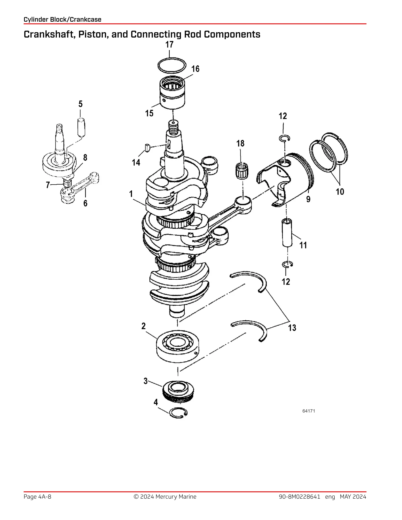
- A – Cylinder Block/Crankcase (powerhead specifications, cylinder block/crankcase components, crankshaft/piston/connecting rod components, inlet manifold components, troubleshooting, compression check, RPM performance test, cylinder block disassembly, powerhead removal, lower end cap and oil seal removal, bleed hose removal, cylinder head removal, exhaust cover removal, timing plate removal, oil pump removal, inlet manifold and reed valve removal/inspection, crankcase and crankshaft removal, piston disassembly, cleaning/inspection/repair, flywheel, cylinder block cleaning/inspection/cylinder bore measurement, cylinder head inspection, piston inspection, crankshaft and bearing inspection, piston rings, cylinder block assembly, piston assembly and ring installation, crankshaft installation, crankcase/inlet manifold/reed valve installation, oil pump installation, timing plate installation, exhaust cover installation, cylinder head installation, bleed hose installation, lower end cap oil seal installation, powerhead installation)
- B – Cooling System (cooling specifications, water pump components, thermostat components, cooling system description, water pump, thermostat removal/installation, thermostat inspection and testing, water flow diagram)
- 5 – Midsection
- A – Cowling, Driveshaft Housing, and Clamp/Swivel Bracket (top cowl components, bottom cowl components, driveshaft housing components, clamp and swivel bracket components manual and power trim, manual tilt components, bottom cowl removal/installation, driveshaft housing removal/disassembly/cleaning/inspection/assembly/installation, clamp/swivel bracket removal/disassembly/assembly/installation)
- 6 – Lower Unit
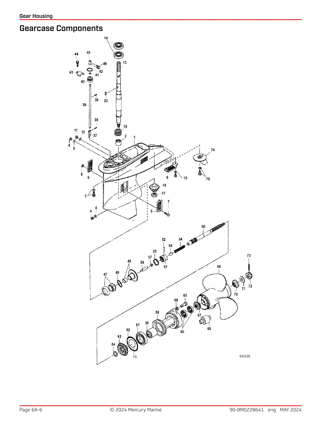
- A – Gear Housing (gearcase specifications, gearcase components, general service recommendations, draining and inspecting gear housing lubricant, gearcase removal, water pump removal, gear housing disassembly, bearing carrier disassembly, propeller shaft disassembly, shift shaft disassembly, driveshaft removal, forward gear and reverse gear inspection, driveshaft pinion bearing removal, driveshaft inspection, upper driveshaft bearing inspection, gear housing assembly, pinion needle bearing installation, forward gear bearing installation, bearing carrier assembly, propeller shaft assembly, pinion gear and driveshaft installation, pinion gear depth, forward gear backlash, reverse gear backlash, shift shaft, propeller shaft and bearing carrier installation, water pump installation, gear housing pressure test, filling gearcase with lubricant, propeller installation, gear housing installation, gearcase installation)
- 7 – Attachments
- A – Throttle and Shift Linkage (gear shift components, throttle linkage components, shift linkage removal/installation, throttle linkage removal/installation)
- B – Tiller Handle (tiller handle components, removal, disassembly, assembly, installation)
- C – Power Trim (power trim specifications, components, troubleshooting, preliminary service checks, electrical troubleshooting, switch test, solenoid test, component troubleshooting, manual valve, pump coupling, filter, power trim unit, air bleed, wire color codes, trim sender/trim meter tests, trim sender removal/installation, power trim assembly removal, unit disassembly, unit assembly, installation)
- D – Remote Control (remote control components, removal, throttle and shift cable removal/installation, handle removal/installation port and starboard, throttle arm and shift gear removal/installation, adjusting screw removal/installation, power harness removal/installation, stop switch removal/installation, main key switch removal/installation, warning buzzer removal/installation, neutral switch removal/installation, neutral lever removal/installation, remote control installation)
- 8 – Recoil Starter
- A – Recoil Starter (components by serial number range, removal, disassembly, cleaning and inspection, assembly, installation)
- 9 – Wiring Diagrams
- A – Color Diagrams (engine harness with remote control, engine harness without remote control, remote control)
Complete PDF Bookmark Tree
Complete Bookmarks
The complete bookmarks in the “Mercury 40/50hp Two Stroke Outboards Service Manual 90-8M0228641 2024” are as follows:
Notice to Users of This Manualp. 3
Precautionsp. 3
Replacement Partsp. 3
Cleanliness and Care of Productp. 4
Copyright and Trademark Informationp. 4
Manual Outlinep. 5
+1A Important Information – Specificationsp. 7
+40/50 Master Specificationsp. 8
+Component Identificationp. 8
40MH/W50MHp. 8
40EH/50EHp. 8
40EHO/50EHOp. 9
40EHPTO/50EHPTOp. 9
40EO/50EOp. 10
40EPTO/50EPTOp. 10
40/50 Specificationsp. 11
Carburetor Specificationsp. 13
Powerhead Specificationsp. 15
Cooling Specificationsp. 16
Ignition Specificationsp. 16
Charging and Starting Specificationsp. 16
Gearcase Specificationsp. 16
Power Trim Specificationsp. 17
+1B Important Information – Maintenancep. 19
+Inspection and Maintenance Schedulep. 20
Daily Checksp. 20
After Each Usep. 20
Annually or 100 Hoursp. 20
Three years or 300 Hoursp. 21
+Flushing the Cooling Systemp. 21
+Top Cowl Removal and Installationp. 22
Removalp. 22
Installationp. 22
Battery Inspectionp. 22
+Fuel Systemp. 22
Fuel Line Inspectionp. 22
Engine Fuel Filterp. 22
Exterior Carep. 23
Fuse Replacement – Electric Start Remote Control Modelsp. 23
Replacing the Anodesp. 23
+Propeller Replacementp. 23
Removing Propellerp. 23
Installing Propellerp. 25
Spark Plug Inspection and Replacementp. 25
Lubrication Pointsp. 26
Changing Gear Oilp. 29
Check Power Trim Fluidp. 31
Submerged Outboardp. 32
+Storagep. 32
Preseason Checkp. 32
+Storage Preparationp. 32
Protecting External Outboard Componentsp. 33
Protecting Internal Engine Componentsp. 33
Gearcasep. 33
Positioning Outboard for Storagep. 33
Battery Storagep. 33
+1C Important Information – General Informationp. 35
Recording Serial Numberp. 36
Model Year Production Codep. 36
+Lanyard Stop Switchp. 36
Keep the Lanyard Stop Switch and Lanyard Cord in Good Operating Conditionp. 37
+Conditions Affecting Performancep. 38
Weatherp. 38
Weight Distribution (Passengers and Gear) Inside the Boatp. 38
Bottom of Boatp. 38
Water Absorptionp. 39
Cavitationp. 39
Elevation and Climatep. 39
Detonationp. 39
+Following Complete Engine Submersionp. 39
Engine Submerged While Running (Special Instructions)p. 39
Saltwater Submersion (Special Instructions)p. 39
Freshwater Submersion (Special Instructions)p. 40
Trim Tab Adjustmentp. 40
Compression Checkp. 40
+Painting Proceduresp. 41
Propellersp. 41
Gear Housingp. 41
+Decal Applicationp. 41
Decal Removalp. 41
+Application Instructionsp. 42
Tools Requiredp. 42
Temperaturep. 42
Surface Preparationp. 42
Decal Applicationp. 42
+1D Important Information – Outboard Installationp. 43
Mercury Marine Validated Engine Mounting Hardwarep. 44
+Installing the Outboardp. 44
Installing the Outboard on the Transomp. 44
+Installing the Remote Control Devicesp. 45
Fitting of Throttle and Shift Cable Adaptersp. 46
Fitting of Remote Control Cable to the Enginep. 46
Connecting Electrical Harnessesp. 47
+Battery Installationp. 47
Mounting Batteryp. 47
Battery Connectionsp. 47
Propeller Selectionp. 48
+Engine Break-in Procedurep. 48
Engine Break-in Fuel Mixturep. 48
Engine Tune-Upp. 48
+2A Electrical – Ignitionp. 51
Ignition Specificationsp. 52
Electrical Componentsp. 54
+Ignition Description of Operation—Ignition Componentsp. 58
Magnetop. 58
Capacitor Discharge (CD) unitp. 58
Ignition Coilp. 58
Main Key Switch and Emergency Stop Switchp. 58
Wire Color Code Abbreviationsp. 59
Warning Horn Testp. 59
Pilot Lamp Testp. 60
+Ignition Troubleshootingp. 61
Ignition System Testingp. 62
+Recommended Diagnostic Procedures—Ignitionp. 62
Ignition Performance Testing Tablesp. 62
Test 1—Spark Testp. 63
+Test 2—Stop Circuit Testp. 63
Test 2a—Stop Circuit Main Key Switch Testp. 64
Test 2b—Stop Circuit Emergency Stop Switch Testp. 65
Test 3—Exciter Coil Testp. 66
Test 4—Pulser Coil Testp. 67
Test 5—CD unit Output Test – Cranking RPMp. 68
Test 6—Ignition Coil Testsp. 69
Test 7—Output Tests – Engine Runningp. 70
+RPM Limitation Testp. 71
Half-Maximum RPM Limitation Testp. 71
Overspeed Limitation Testp. 73
+Flywheel Removal, Inspection, and Installationp. 74
Removalp. 74
Inspectionp. 75
Installationp. 75
+Coil Plate Assembly Removal, Cleaning, Inspection, and Installationp. 76
Removalp. 76
Cleaningp. 77
Inspectionp. 78
Installationp. 78
+Exciter Coil Removal, Cleaning, Inspection, and Installationp. 80
Removalp. 80
Cleaningp. 81
Inspectionp. 81
Installationp. 81
+Ignition Coil Removal, Cleaning, Inspection, and Installationp. 83
Removalp. 83
Cleaningp. 84
Inspectionp. 84
Installationp. 84
+CD unit Removal, Inspection, and Installationp. 84
Removalp. 84
Inspectionp. 86
Installationp. 86
+2B Electrical – Charging and Starting Systemp. 89
Charging and Starting Specificationsp. 90
Electrical Componentsp. 92
Wire Color Code Abbreviationsp. 96
+Batteryp. 96
Recommended Batteryp. 96
Troubleshooting Battery Charging Systemp. 96
+Battery Charging System Testsp. 96
Alternator Coil Testp. 96
Rectifier/Regulator Diode Testp. 97
+Rectifier/Regulator Removal and Installationp. 98
Removalp. 98
Installationp. 99
+Alternator Coil Removal, Cleaning, Inspection, and Installationp. 101
Removalp. 101
Cleaningp. 102
Inspectionp. 102
Installationp. 102
+Starting Systemp. 104
+Starting System Componentsp. 104
Descriptionp. 104
Batteryp. 104
Main Key Switchp. 104
Neutral Start Switchp. 104
Starter Solenoidp. 104
Starter Motorp. 104
Engine Fuse (20-Amp)p. 104
Starting System Wiring Diagramp. 105
Starting System Descriptionp. 105
Starter System Testingp. 106
+Starter Circuit Testsp. 106
Models With Remote Control Boxp. 106
Models Without Remote Control Boxp. 109
Starter Solenoid Testp. 112
+Starter Solenoid Removal and Installationp. 113
Removalp. 113
Installationp. 114
Main Key Switch Testp. 114
+Neutral Start Switch Testp. 119
Engines With A Remote Control Boxp. 119
Engines Without A Remote Control Boxp. 121
+Neutral Start Switch Removal and Installationp. 122
Removalp. 122
Installationp. 122
Choke Solenoid Testp. 123
+Choke Solenoid Removal and Installationp. 123
Removalp. 123
Installationp. 124
+Starter Motorp. 124
Starter Motor Testsp. 124
Starter Motor Removalp. 124
+Starter Motor Disassembly and Reassemblyp. 126
Pinion Removal, Inspection, and Assemblyp. 126
Starter Motor Disassemblyp. 126
Brush Assembly Inspectionp. 126
Brush Assembly Removalp. 127
Brush Assembly Installationp. 127
Starter Motor Assemblyp. 127
Starter Motor Brush Assembly Testingp. 127
Starter Motor Installationp. 128
+2C Electrical – Timing, Synchronizing, and Adjustingp. 131
Ignition Specificationsp. 132
Throttle Linkage Componentsp. 134
+Ignition Timing and Throttle Cable Adjustmentp. 136
Ignition Timing Adjustmentp. 136
Carburetor Synchronizationp. 141
Oil Pump Aperture Adjustmentp. 145
+3A Fuel System – Carburetor and Fuel Pumpp. 147
Carburetor Specificationsp. 148
Carburetor Componentsp. 150
Air Silencer Componentsp. 152
Fuel Line Componentsp. 154
Oil Injection Componentsp. 156
+Theory of Operationp. 158
Fuel Flowp. 158
Oil Pump (Oil Injected Models Only)p. 158
Fuel Pumpp. 158
+Carburetorsp. 158
Pilot Systemp. 158
Main Systemp. 158
Recirculationp. 158
Mixture Enrichmentp. 158
+Fuel System Requirementsp. 158
Acceptable Fuelp. 158
Unacceptable Fuelp. 158
Fuel Storage Lifep. 159
Acceptable Lubricantp. 159
+Mix Ratiosp. 159
Auto-mixingp. 159
Premixingp. 159
Anti-Siphon Valvesp. 159
+Carburetor Adjustmentsp. 159
+Diagnostics and Troubleshootingp. 159
+Engine Fuel Filterp. 161
Cleaning the Fuel Filters and the Fuel Tankp. 162
Carburetor Removalp. 162
+Fuel Pumpp. 164
Removalp. 164
Disassemblyp. 164
Cleaningp. 165
Inspectionp. 165
Assemblyp. 165
Installationp. 166
Carburetor and Fuel Pump Disassemblyp. 166
+Carburetor Cleaning and Inspectionp. 167
Cleaningp. 167
Inspectionp. 167
+Carburetor and Fuel Pump Assemblyp. 168
Carburetor Installationp. 170
+Oil Tankp. 172
Removalp. 172
Installationp. 173
+Oil Pumpp. 175
Removalp. 175
Installationp. 175
+Fuel and Oil Filtersp. 175
Disassemblyp. 175
Cleaningp. 176
Inspectionp. 176
Assemblyp. 176
+Auto-Mixing Systemp. 176
Inspectionp. 176
Purging the Auto-Mixing Systemp. 177
+Function Testsp. 178
Oil Pump Output Testp. 178
Oil Level Sensor Testp. 179
Auto-Mixing Check Valve Function Testp. 180
+4A Powerhead – Cylinder Block/Crankcasep. 183
Powerhead Specificationsp. 185
Cylinder Block/Crankcase Componentsp. 186
Crankshaft, Piston, and Connecting Rod Componentsp. 190
Inlet Manifold Componentsp. 192
+Troubleshootingp. 194
Compression Checkp. 194
RPM Performance Testp. 195
+Cylinder Block Disassemblyp. 195
Powerhead Removalp. 195
Lower End Cap and Oil Seal Removalp. 200
Bleed Hose Removalp. 200
Cylinder Head Removalp. 201
Exhaust Cover Removalp. 202
Timing Plate Removalp. 203
Oil Pump Removalp. 203
+Inlet Manifold and Reed Valve Removal and Inspectionp. 204
Disassemblyp. 204
Inspectionp. 205
Crankcase and Crankshaft Removalp. 206
Piston Disassemblyp. 209
+Cleaning/Inspection/Repairp. 210
Flywheelp. 210
Cylinder Block Cleaning, Inspection, and Cylinder Bore Measurementp. 211
Cylinder Head Inspectionp. 211
Piston Inspectionp. 212
+Crankshaft and Bearing Inspectionp. 212
Crankshaft Runoutp. 212
Crankshaft Measurementp. 213
Crankshaft and Connecting Rod Bearingsp. 213
+Piston Ringsp. 213
Piston Ring End Gap Clearancep. 213
+Cylinder Block Assemblyp. 214
Piston Assembly and Ring Installationp. 214
Crankshaft Installationp. 215
Crankcase, Inlet Manifold, and Reed Valve Installationp. 217
Oil Pump Installationp. 219
Timing Plate Installationp. 220
Exhaust Cover Installationp. 220
Cylinder Head Installationp. 221
Bleed Hose Installationp. 222
Lower End Cap Oil Seal Installationp. 223
Powerhead Installationp. 224
+4B Powerhead – Cooling Systemp. 231
Cooling Specificationsp. 232
Water Pump Componentsp. 234
Thermostat Componentsp. 236
Cooling System Descriptionp. 236
Water Pumpp. 236
+Thermostatp. 236
Removalp. 236
Installationp. 237
Thermostat Inspection and Testingp. 238
Water Flow Diagramp. 239
+5A Midsection – Cowling, Driveshaft Housing, and Clamp/Swivel Bracketp. 241
Top Cowl Componentsp. 244
Bottom Cowl Components (0N134078 and Below)p. 246
Bottom Cowl Components (0N134079 and Above)p. 248
Driveshaft Housing Componentsp. 250
Clamp and Swivel Bracket Components (Manual)p. 252
Clamp and Swivel Bracket Components (Power Trim)p. 256
Manual Tilt Componentsp. 260
+Bottom Cowlp. 262
Removalp. 262
Installationp. 262
+Driveshaft Housingp. 262
Driveshaft Housing Removalp. 262
Driveshaft Housing Disassemblyp. 264
Driveshaft Housing Cleaning and Inspectionp. 265
Driveshaft Housing Assemblyp. 267
Driveshaft Housing Installationp. 271
+Clamp/Swivel Bracketsp. 273
Clamp/Swivel Bracket Removalp. 273
Clamp/Swivel Bracket Disassemblyp. 274
Clamp/Swivel Bracket Assemblyp. 275
Clamp/Swivel Bracket Installationp. 277
+6A Lower Unit – Gear Housingp. 279
Gearcase Specificationsp. 280
Gearcase Componentsp. 284
+General Service Recommendationsp. 288
Bearingsp. 288
Shimsp. 288
Sealsp. 288
Draining and Inspecting Gear Housing Lubricantp. 288
Gearcase Removalp. 289
Water Pump Removalp. 290
+Gear Housing Disassemblyp. 293
Bearing Carrier Disassemblyp. 293
Propeller Shaft Disassemblyp. 297
Shift Shaft Disassemblyp. 299
Driveshaft Removalp. 301
Forward Gear and Reverse Gear Inspectionp. 302
Driveshaft Pinion Bearing Removalp. 303
Driveshaft Inspectionp. 305
Upper Driveshaft Bearing Inspectionp. 305
+Gear Housing Assemblyp. 306
Pinion Needle Bearing Installationp. 306
Forward Gear Bearing Installationp. 307
Bearing Carrier Assemblyp. 308
Propeller Shaft Assemblyp. 311
Pinion Gear and Driveshaft Installationp. 312
Pinion Gear Depthp. 313
Forward Gear Backlashp. 314
Reverse Gear Backlashp. 317
Shift Shaftp. 320
Propeller Shaft and Bearing Carrier Installationp. 320
Water Pump Installationp. 321
Gear Housing Pressure Testp. 324
Filling Gearcase with Lubricantp. 325
Propeller Installationp. 325
Gear Housing Installationp. 326
Gearcase Installationp. 327
Filling Gear Housing with Lubricantp. 328
+7A Attachments – Throttle and Shift Linkagep. 329
Gear Shift Componentsp. 332
Throttle Linkage Componentsp. 334
Shift Linkage Removalp. 336
Shift Linkage Installationp. 337
Throttle Linkage Removalp. 339
Throttle Linkage Installationp. 340
+7B Attachments – Tiller Handlep. 343
Tiller Handle Componentsp. 346
Tiller Handle Removalp. 348
Tiller Handle Disassemblyp. 349
Tiller Handle Assemblyp. 350
Tiller Handle Installationp. 352
+7C Attachments – Power Trimp. 355
Power Trim Specificationsp. 356
Power Trim Componentsp. 358
Power Trim Componentsp. 360
+Power Trim Troubleshootingp. 362
+Preliminary Service Checksp. 362
Service Check Onep. 362
Service Check Twop. 362
Service Check Threep. 363
Service Check Fourp. 363
Service Check Fivep. 363
Power Trim Electrical Troubleshootingp. 364
Power Trim Switch Testp. 364
Power Trim Solenoid Testp. 365
Power Trim Component Troubleshootingp. 367
Manual Valvep. 368
Pump Couplingp. 368
Filterp. 369
Power Trim Unitp. 370
Air Bleedp. 370
Wire Color Code Abbreviationsp. 372
+Trim Sender/Trim Meter Testsp. 372
Analog Trim Indicator Input Voltage Testp. 372
LCD Trim Indicator Input Voltage Testp. 373
Analog Trim Meter Output Voltage Testp. 375
LCD Trim Meter Output Voltage Testp. 376
Analog Trim Sender Output Voltage Testp. 377
LCD Trim Sender Output Voltage Testp. 378
+Trim Senderp. 379
Trim Sender Removalp. 379
Installationp. 380
+Power Trim Assemblyp. 381
Power Trim Removalp. 381
Power Trim Unit Disassemblyp. 383
Power Trim Unit Assemblyp. 385
Power Trim Installationp. 389
+7D Attachments – Remote Controlp. 391
Remote Control Componentsp. 394
Remote Control Removalp. 396
Remote Control Throttle And Shift Cable Removalp. 396
Remote Control Throttle And Shift Cable Installationp. 397
Remote Control Handle Removal (Port)p. 398
Remote Control Handle Installation (Port)p. 400
Remote Control Handle Removal (Starboard)p. 403
Remote Control Handle Installation (Starboard)p. 405
Remote Control Throttle Arm And Shift Gear Removalp. 408
Remote Control Throttle Arm And Shift Gear Installationp. 409
Remote Control Adjusting Screw Removalp. 412
Remote Control Adjusting Screw Installationp. 413
Remote Control Power Harness Removalp. 414
Remote Control Power Harness Installationp. 416
Remote Control Stop Switch Removalp. 418
Remote Control Stop Switch Installationp. 419
Remote Control Main Key Switch Removalp. 421
Remote Control Main Key Switch Installationp. 422
Remote Control Warning Buzzer Removalp. 424
Remote Control Warning Buzzer Installationp. 425
Remote Control Neutral Switch Removalp. 426
Remote Control Neutral Switch Installationp. 428
Remote Control Neutral Lever Removalp. 430
Remote Control Neutral Lever Installationp. 431
Remote Control Installationp. 433
+8A Recoil Starterp. 435
Recoil Starter Components (Serial Number 0N250805 and Below)p. 438
Recoil Starter Components (Serial Number 0N25086 and Up)p. 440
Recoil Starter Removalp. 442
Recoil Starter Disassemblyp. 442
+Recoil Starter Cleaning and Inspectionp. 445
Cleaningp. 445
Inspectionp. 445
Recoil Starter Assemblyp. 446
Recoil Starter Installationp. 448
+9A Wiring Diagrams – Color Diagramsp. 451
40/50 TwoStroke Engine Harness With Remote Controlp. 454
40/50 TwoStroke Engine Harness Without Remote Controlp. 457
Remote Controlp. 458
Blank Pagep. 2
Blank Pagep. 459
What makes this manual genuinely useful is the way it is organised around real service work rather than theory. The specification section alone covers master specifications, carburetor jetting for 40D, 40D2, 50D and 50D2 variants, powerhead tolerances, cooling, ignition, charging and starting, gearcase and power trim values in one place. From there the manual moves through the ignition system with DVA-based diagnostic tests for the exciter coil, pulser coil and CD unit, the fuel system with carburetor disassembly and auto-mixing oil pump adjustment, the powerhead with full cylinder block and crankshaft teardown, the midsection with driveshaft housing and swivel bracket rebuilds, the gear housing with pinion gear depth shimming and forward/reverse gear backlash measurement, and the attachments sections covering throttle and shift linkage, tiller handle, power trim hydraulics and remote control rebuilds.
Whether you are diagnosing a no-start condition on a 50EHPT, rebuilding the gearcase on a 40MH, synchronising carburetors on a 50D2, adjusting oil pump aperture, setting ignition timing at idle and WOT, replacing a water pump impeller, shimming a pinion gear, testing a power trim solenoid or tracing a wiring fault through the colour diagrams, the procedure and the factory numbers are here. The wiring diagrams section alone justifies the download for anyone chasing electrical gremlins through a tiller or remote control harness.
Why This Mercury 40/50hp Service Manual Matters
Two-stroke outboards are unforgiving of guesswork. Ignition timing that is a couple of degrees out, a carburetor that is not synchronised, an oil pump aperture that is misadjusted or a gearcase that is shimmed wrong will all shorten engine life or leave you stranded on the water. This Mercury 40/50hp Two Stroke Outboards Service Manual 90-8M0228641 gives you the actual factory procedures and the actual factory numbers – torque values, clearances, backlash ranges, DVA readings, float heights, pilot screw settings, jet sizes and service limits – so the work is done once, correctly.
It supports the full range of jobs on these engines: routine maintenance from gear oil changes and impeller replacement through to complete powerhead disassembly, crankshaft and piston inspection, bearing carrier rebuilds, shift shaft service, power trim unit disassembly and remote control overhaul. For a dealer technician, a marine mechanic or an owner who prefers to do the work properly, this is the reference that turns a difficult two-stroke repair into a documented procedure.
Delivered as an instant PDF download with no shipping and no waiting. Read it on a laptop, tablet or phone in the workshop, or print the pages you need for the job at hand. The manual is fully navigable and the diagrams hold up on screen for close inspection.



Reviews
There are no reviews yet.