
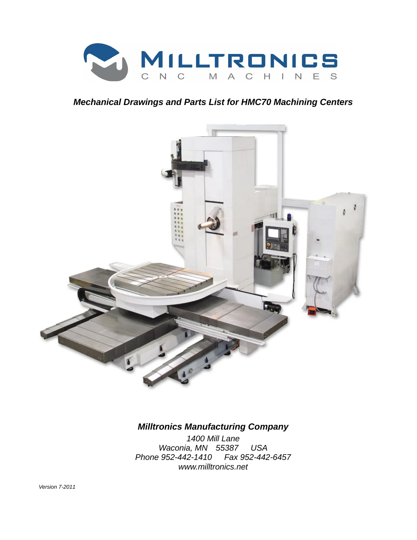
Milltronics HMC70 Machining Center Operation Mechanical Drawings and Parts Manual 2011
Original price was: $39.95.$24.95Current price is: $24.95.
Complete 410-page Milltronics HMC70 operation, mechanical drawings and parts manual for the 2011 HMC70 machining center, covering specifications, maintenance, parts identification, assembly, adjustment and diagrams.
Description
Milltronics HMC70 Machining Center Manual Overview
The Milltronics HMC70 Machining Center Operation Mechanical Drawings and Parts Manual 2011 is a 410-page technical document for the HMC70 horizontal machining center. It combines operation guidance with mechanical drawings, parts lists, inspection schedules, adjustment data, assembly procedures, pipe distribution information, rotary table operation and electrical diagram sections. The cover identifies Milltronics Manufacturing Company of Waconia, Minnesota, and marks the document as Version 7-2011, while the chapter pages carry Version 009 dated August 2009.
This manual is aimed at operators, maintenance staff and technical personnel who need to understand the HMC70 machine structure, locate parts, follow periodic inspection routines, interpret adjustment procedures or reference system diagrams. It is not limited to a single topic: the contents move from machine specifications and main components through installation preparation, circuit diagrams, maintenance data, parts drawings, assembly steps and controller operating procedures.
File Details
- Manual type: Operation, mechanical drawings and parts manual
- Brand: Milltronics Manufacturing Company
- Model: HMC70
- Language: English
- Page count: 410
- File format: PDF
- Cover version: 7-2011
- Chapter version: Version 009, August 2009
Chapters Covered
- 1 General Specification: general specification, layout, coordinate system and machine reference point, limitations and specifications
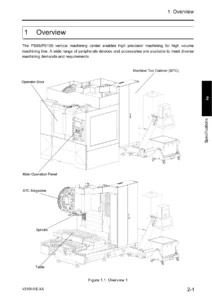
- 2 Main Components: main components, ATC, table, head, axes system, spindle oil cooler system, hydraulic system, pneumatic system, auto lubrication unit, coolant system and chip remove devices, electric devices and name plates
- 3 Transport-Installation and Preparation for Operation: machine location, foundation plan, preparation before machine arrival, transportation, installation, power and air source connection, disassembling of fixtures and cleaning, supplying oil, final leveling and inspection
- 4 Circuit Diagrams: hydraulic system, air service unit, air filter, regulator and lubricator assembly
- 5 Periodic Inspection: arm type ATC, table, axes system, spindle head, air service unit, lubrication unit, oil cooler option, name plates, coolant and chip devices, electric device and periodic check of oil
- 6 Data for Adjustment and Maintenance: regular inspection list, oiling charts, maintenance instruction, lubrication system, axes system, chip drawer, air service unit, lubrication unit, coolant and chip device, air filter cleaning, horizontal borer maintenance steps, fittings, motor, control units and wire connectors
- 7 Parts Drawing and Specification: head stock, W-axis, W-axis with CTS, W-axis transmission, spindle transmission, rotary table drawings, X-axis, Z-axis, base, Y-axis, counter balance weight, swivel type panel, floor type console, electric cabinet assembly, table guard, ATC and safety guard option
- 8 Assembly Procedure: base, carriage, auxiliary guide way, column, ATC, chip auger, chip conveyor, sheet metal, oil cooler and hydraulic unit and coolant tank, X/Y/Z cable carrier, wiring and piping set-up, telescopic way cover and facing head option
- 9 Distribution of Pipes: plumbing diagrams for hydraulic, oil cooler, coolant, lubrication, air and scales
- 10 Operation Manual of Rotary Table: safety introduction, specifications and characteristics, installation and preparation, operating the machine, maintenance and trouble shooting
- 11 Controller Operational Procedure: power on, warming up, main operation panel, options, sub panel, M code list and description, tool probe description, ATC action of swing arm, magazine trouble shooting, option head, alarm and operation messages
- 12 Electrical Diagrams
For a technician working with the HMC70, the value of this document is in how it links machine-level information together. A parts drawing can be checked against the relevant assembly procedure, an inspection item can be read alongside the adjustment section, and the specification pages provide the travel, table, spindle, feed, ATC and motor data needed to understand the machine before work begins. The manual also records recommended oil types and quantities, periodic inspection intervals, hydraulic and pneumatic pressures, ATC component functions and rotary table maintenance details.
Machine Areas and Technical Scope
The general specification section lists HMC70 travel values of 2200 mm on X, 1600 mm on Y, 1600 mm on Z and 550 mm on W. The table is given as 1200 x 1500 mm with a maximum loading weight of 5000 kg. Spindle taper is ISO No. 50, spindle speed is listed as 35 to 3000 rpm and the spindle is described with a two-step automatic speed change. Rapid feed for X, Y and Z is 12000 mm/min, while 3-axis cutting feed is listed as 1 to 5000 mm/min. The ATC is shown with 60 pockets, maximum tool diameter of 125/250 mm, maximum tool length of 300 mm, maximum tool weight of 25 kg and a tool-to-tool change time of 9 seconds. Total machine weight is stated as 22500 kg.
The main components chapter explains the base, carriage, table, column, head, ATC, electric cabinet and chip conveyor, and then separates the machine into systems. The ATC section covers the arm, tool magazine, tool pocket, guard and manual magazine controls. The table section includes loading and dimension information plus notes on the HBM4 index table motor installation for frame-only arrangements. The head section describes the spindle, driving unit, encoder and tool unclamp device, and includes spindle bearing maintenance guidance and clamping force test values. The axes section lists ballscrew dimensions, positioning accuracy and repeatability. Separate sections address the spindle oil cooler, hydraulic system, pneumatic system, auto lubrication unit, coolant system, chip removal devices, electric devices and name plates.
Installation and preparation content covers environmental requirements, foundation planning, temporary leveling, mortar filling, power and air source connection, fixture removal, cleaning and oil supply. The manual gives a power capacity of 50 kVA and a cable section area of 22 mm2 for the power connection example, and it describes air source connection requirements with a pressure range of 5.5 to 7.5 kgf/cm2. These are the kinds of details a maintenance technician needs when preparing the machine area and checking services before operation.
Maintenance, Adjustment and Parts Reference
The periodic inspection chapter sets out inspection points for the arm type ATC, table, axes system, spindle head, air service unit, lubrication unit, oil cooler option, name plates, coolant and chip devices, and electric devices. The adjustment and maintenance chapter expands this into regular inspection lists, oiling charts and step-by-step maintenance instructions. It includes procedures for inspecting the lubrication system, adjusting reference points on X, Z and Y axes, adjusting gibs on X and Z axes, cleaning the chip drawer, adjusting air pressure, setting the oiler flow rate, supplying oil to the oilier, extracting water from the filter unit, cleaning filters, adjusting the pressure switch, checking the lubrication unit, servicing the coolant tank and chip pan, applying grease to the chip conveyor and cleaning the air filter option.
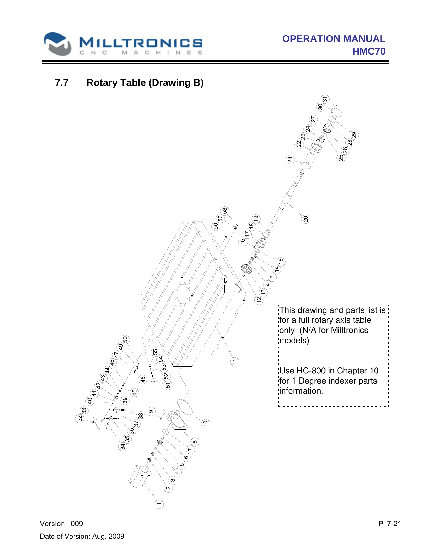
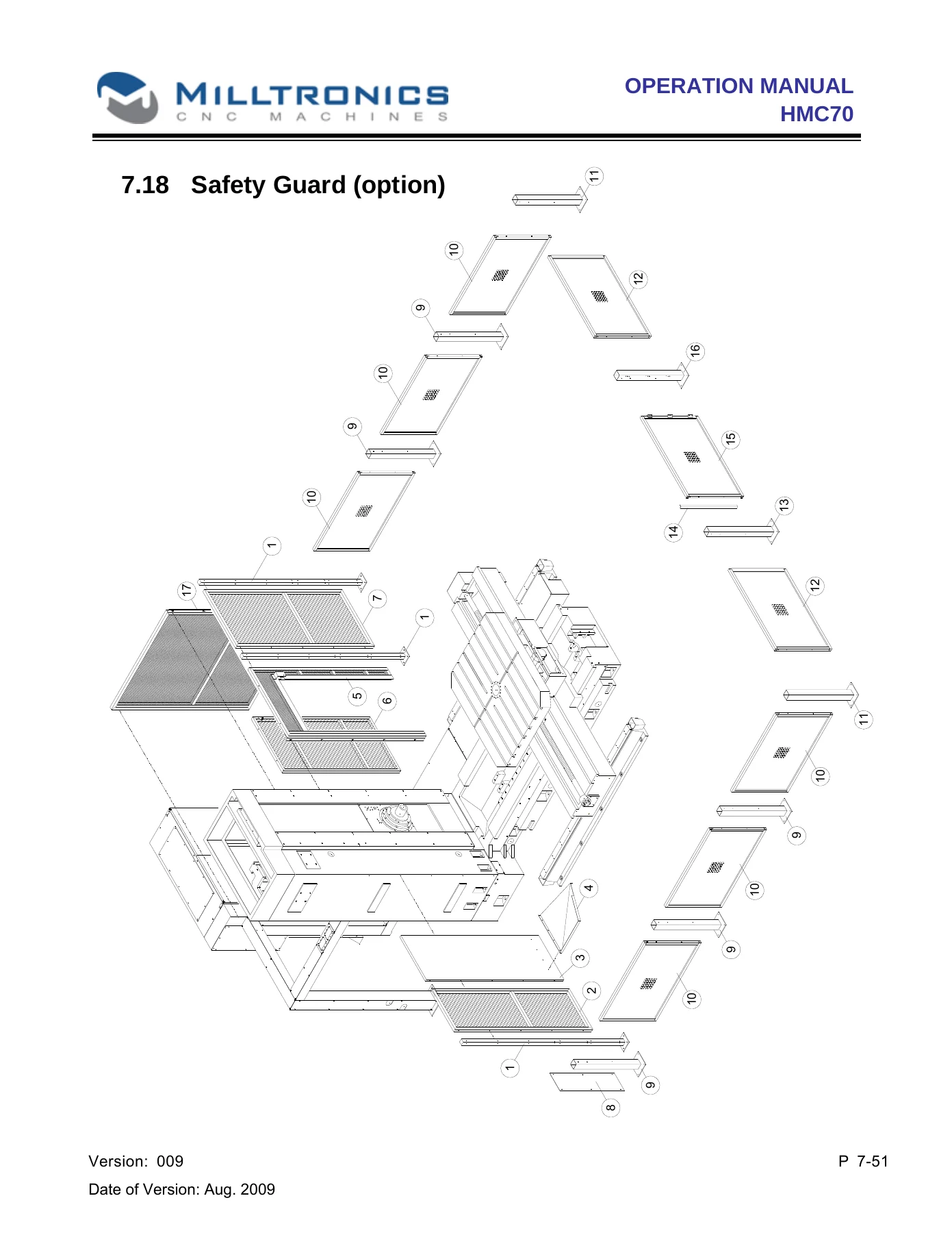
The parts drawing and specification chapter is organized by machine assembly. It includes head stock, W-axis, W-axis with CTS, W-axis transmission, spindle transmission, rotary table drawing A and drawing B, X-axis, Z-axis, base, Y-axis, counter balance weight, swivel type panel, floor type console, electric cabinet assembly, table guard, ATC and safety guard option. Each parts list provides item numbers, part numbers where shown, descriptions, quantities and remarks such as screw sizes, bearing numbers, motor variants and option notes. This makes the manual useful for identifying a component before ordering or replacing it, and for understanding how the assembly is put together.
The assembly procedure chapter goes further into the sequence for base, carriage, auxiliary guide way, column, ATC, chip auger, chip conveyor, sheet metal, oil cooler and hydraulic unit and coolant tank, cable carriers, wiring and piping set-up, telescopic way cover and the facing head option. The ATC assembly section includes leveling, chain fixing, arm adjustment, tool pocket alignment and trouble shooting cases. The facing head option section gives separate procedures for Fanuc and Heidenhain controller arrangements, including spindle orientation codes and transmission shaft alignment steps.
Rotary Table and Controller Information
Chapter 10 is a dedicated rotary table manual covering safety introduction, specifications, dimensions, installation and preparation, operating preparation, maintenance and trouble shooting. It describes an HC-800H-B table with a 1500 x 1200 mm turntable, 60 mm center hole, 425 mm overall height, 22 mm T-slot width, 11.1 rpm rotation speed, 1/180 total speed reduction ratio and hydraulic brake torque of 4050 kg-m. It also gives indexing accuracy of +/- 5 seconds, repeatable accuracy of 1 second and hydraulic pressure of 35 bar. Maintenance topics include worm gear backlash measurement and adjustment, clamp and unclamp confirmation adjustment, zero return system adjustment, lubricant recommendations and a maintenance schedule.
Chapter 11 covers controller operational procedure with power on, machine ready checks, axes reference, warming up, main operation panel functions, mode selection, spindle controls, feed controls, over travel release, cycle start, feed hold, feed rate override, rapid override, spindle override, alarm signal, program stop, memory protect key and options. It also includes a sub panel section for horizontal machines, an M code list, tool probe description, ATC swing arm action, magazine trouble shooting, option head setup and alarm and operation message lists. Chapter 12 contains electrical diagrams.
The Milltronics HMC70 Machining Center Operation Mechanical Drawings and Parts Manual 2011 supports practical tasks such as checking machine specifications, preparing for installation, identifying parts from assembly drawings, following periodic inspection schedules, adjusting axis reference points and gibs, servicing the lubrication and coolant systems, understanding ATC and rotary table maintenance, and referencing controller operations and alarm messages. Having the correct HMC70 procedures and part references in one PDF helps reduce guesswork when maintaining or repairing the machine and gives operators a clear reference for the machine systems they work with.
IMAGES PREVIEW
Delivered as an instant PDF download, this Milltronics HMC70 manual can be stored on a shop computer, tablet or phone and printed for use at the machine. There is no shipping delay, so the document is available immediately after purchase for operators, maintenance staff and technical references.
Reviews
There are no reviews yet.