Mindray A5 A4 A3 Anesthesia System Service Manual PDF Download
Original price was: $95.00.$18.95Current price is: $18.95.
Official Mindray DS USA factory service manual for the A5™, A4™ & A3™ Anesthesia Systems — the complete technical reference for biomedical engineers and authorised service personnel. Covers theory of operation, installation, calibration, periodic maintenance, full disassembly/reassembly, alarm troubleshooting, pneumatic circuit diagnosis, and replacement parts — with electrical and pneumatic diagrams. 482 pages of OEM documentation. Instant PDF download.
Description
Mindray A5 A4 A3 Anesthesia System Service Manual PDF Download
DESCRIPTION
Mindray A5™ / A4™ / A3™ Anesthesia System — Official Factory Service Manual
This is the genuine Mindray DS USA, Inc. factory service manual for the A5™, A4™, and A3™ Anesthesia Systems — part number 046-001141-00, Version 25.0 (December 26, 2019). Covering all three variants in a single comprehensive document, these 482 pages of OEM-level technical documentation are the definitive reference for authorised service personnel, hospital biomedical/HTM departments, and Mindray-certified field engineers performing installation, calibration, periodic maintenance, repair, and full system disassembly on these continuous-flow inhalation anesthesia workstations.
📋 File Details
| Detail | Info |
|---|---|
| Manual Type | OEM Factory Service Manual |
| Publisher | Mindray DS USA, Inc. |
| Part Number | 046-001141-00 (Ref: H-046-001141-00) |
| Version | 25.0 — December 26, 2019 |
| Models Covered | A5™, A4™, A3™ Anesthesia Systems |
| Copyright | © Mindray DS USA, Inc., 2010–2019 |
| Total Pages | 482 pages |
| PDF Quality | Clear digital factory document — readable schematics, connection diagrams, calibration tables, and step-by-step procedures throughout |
📑 Table of Contents
- Chapter 1 — Theory of Operation
- 1.1 Introduction — system overview, continuous-flow inhalation design
- 1.2 Electrical and Pneumatic Connections
- A3/A4 Electrical Connections
- A5 Electrical Connections
- A3/A4 Pneumatic Connections
- A5 Pneumatic Connections
- Connections Between Pneumatic Circuit, Breathing System, and Ventilator Control Board
- 1.3 Gas Flow
- Pneumatic Circuit Diagram & Parts List
- Anesthetic Gas Delivery System
- Gas Supplies / System Switch Assembly
- Flow Adjust and Control Assembly / Flow Display Assembly
- O2 Flush Button Assembly / Vaporizer Manifold
- CGO Assembly / Auxiliary O2 and Air Supply Assembly
- High Pressure O2 Output Assembly (A5 Only)
- Anesthetic Ventilator / Breathing System
- Anesthetic Gas Scavenging System / Dynamic Gas Scavenging System
- 1.4 Anesthesia System Components — Auxiliary Outlets, Work Light Board
- 1.5 The Breathing System
- Automatic Mode Inspiration & Expiration
- Manual Mode Inspiration & Expiration
- Pneumatic PEEP / Standby Mode
- Ventilation Bellows, Manual Bag, CO2 Absorber, Inspiratory/Expiratory Valves, APL Valve
- 1.6 Ventilator UI
- Display Interface Board / Backlight Inverter Board
- Screen Backlight Board / Warning Light Board
- Flow Control Board / Indicator Light Board / CPU Board
- 1.7 Ventilator Control and Drive
- Mother Board / Ventilator Control and Drive Board
- Monitor Signal Detection Board / Valve Drive Board / Sensor Interface Board
- Battery (Power + Battery Adaptation Board)
- Infrared Communication Board / Breathing System Heater
- 1.8 Ventilator Pneumatic — O2 Drive Gas
- Drive Pressure High Pressure Regulator (200 kPa / 29 psi)
- Drive Gas Assembly / Tube Color Coding
- Chapter 2 — Installation Guide
- 2.1 Preparation — Additional Material Required
- 2.2 Assembly
- Unpacking and Setup (full step-by-step)
- Breathing System and Accessories Checkout
- Vaporizer Mounting, Filling, and Draining
- Monitoring Products Mounting and Electrical Connection
- 2.3 Software and License Key Installation
- 2.4 Functional Tests
- Breathing System Leak Test — Mechanical & Manual Ventilation Modes + Troubleshooting
- AG Module Accuracy Check / Gas Module Verification
- Gas Delivery System Tests: O2 Flush, O2:N2O Ratio, Vaporizer Leak, Check Valve
- Sensor Zero Point / Flow Sensor Accuracy / Pressure Sensor Accuracy
- Electronic Flowmeter Accuracy Check
- 2.5 Pneumatic Leak Tests
- N2O, O2, AIR Cylinder Leak Tests (A5/A3 and A5)
- Line Pressure Leak Tests / Line Pressure Gauge Accuracy Test
- 2.6 Breathing System Checks
- Waste Gas Scavenger Test / Internal Gas Connections / Drive Gas Pressure Loss Alarm / N2O Cutoff
- 2.7 Performance Verification
- Manual & Manual Mode Ventilation / APNEA Alarm / Alarm Silence
- VCV Adult & Child / PCV Adult / Pressure Support (PS) Mode Tests
- Airway Disconnect Alarm
- 2.8 Alarms and Fail-Safe Functions
- Low/High FiO2 Alarms / Peak Pressure Alarms / Minute Volume Alarm
- 2.9 Miscellaneous Tests — Line Voltage Alarm, Lights, Touchpad/USB
- 2.10 Vaporizer Interlock Test / 2.11 Vaporizer Accuracy Test
- 2.12 Electrical Tests — Auxiliary Outlet, Electrical Safety Inspection Form
- Chapter 3 — Periodic Maintenance
- 3.1–3.3 Maintenance Schedule & Consumable Parts Kits
- 3.4 Pre-surgery Checklist / 3.5 Visual Inspection Checklist
- 3.6 List of Periodic Maintenance Parts to Replace and Check
- 3.7 Battery Maintenance and Replacement
- 3.8–3.16 Full Repeat of All Functional, Pneumatic, Breathing, Performance, Alarm & Electrical Tests for Periodic Maintenance
- Chapter 4 — Calibration
- 4.1 Introduction / 4.2 Calibration Warnings, Precautions, and Notes
- 4.3 System Calibration
- O2 Sensor Calibration (21% and 100% O2)
- Flow Calibration — User and Service Level (Auto & Manual, Software ≥01.00.00)
- Pressure Calibration — Service Level
- Pressure and Flow Zeroing — Service Level
- Electronic Flowmeter Zeroing — User Level
- AG Module Calibration (A5/A4 with Gas Module)
- ORC Calibration / Cylinder Yoke Regulator Calibration
- Back Pressure Valve Adjustment
- Chapter 5 — Repair and Troubleshooting
- 5.1 Troubleshooting Guidelines
- 5.2 Technical Alarms Check
- Startup Alarm Messages / CPU Board Runtime Alarm / Power Board Runtime Alarm
- Fresh Flow Sensor Board Alarm / Ventilator Control Board Alarm
- Real-time Alarms of External AG Module
- 5.3 Pneumatic Circuit System Problems
- On-site Maintenance Tools & Test Fixtures
- Gas Supplies and Drive Gas / Pipeline Pressure, Regulator, Pressure Switch Tests
- Anesthetic Gas Delivery System Leak Tests
- Breathing System Leak Tests / Tidal Volume Troubleshooting
- 5.4 Sensors and Valves Problems
- Pneumatic Circuit / Hardware Component Correspondence
- Flow & Pressure Sensor Zero Point Problems
- Inspiratory Valve / PEEP Safety Valve / PEEP Valve Diagnostics
- 5.5 Hardware and Electrical Problems
- 5.6 Software Update and Configuration Activation
- 5.7 Factory Setup
- Chapter 6 — Repair and Disassembly
- 6.1 Prepare for Disassembly — Tools, Preparations, Bleed Gas Pressure
- 6.2 Disassemble the Assemblies
- Machine Upper Half: Gas Supply Inlet, Pressure Regulator, Electronic Flowmeter, Poppet Valve, Gas Mixer, ORC, Back Pressure Valve, Battery, Vaporizer Manifold, Pneumatic Resistor Block
- Hardware Box: CPU Board, Ventilator Control Board, Power Board, Solenoid Valve, Speaker, Rear Panel
- Work Surface: Drawer, Cover Plates, Drive Gas Assembly, O2 Flush, Touch Panel (A5), CGO Assembly, Cylinder Bracket, Spring Tube
- Display: Alarm Lamp Board, Display Adaptation Board, Touch Screen Control Board, Backlight Inverter Board, Needle Valve Assemblies, Touch Screen, Display Replacement Package
- Module Rack Assembly / Module Rack Fan / Panel of Pressure Gauges
- System Switch / Indicator Light Board / Auxiliary Gas Outlet
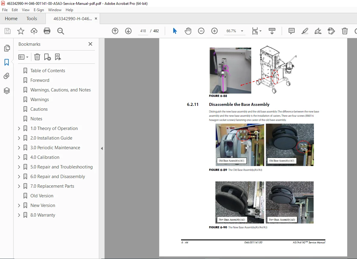
- AGSS Assembly / Base Assembly (Caster, Brake System — A5 Only)
- 6.3 Disassemble the Breathing System
- O2 Sensor, Breathing Tubes, Flow Sensor, Manual Bag
- Absorbent Canister, CO2 Bypass Assembly, Patient Circle Assembly
- Bellows Assembly, Pop-off Valve, Expiratory/Inspiratory Check Valves
- Water Collection Cup, Airway Pressure Gauge, Bag Arm
- Front/Back Covers, Auto/Manual Ventilation Switch, APL Valve Assembly
- Chapter 7 — Replacement Parts
- 7.1 Ordering Replaceable Parts
- Illustrated Parts Diagrams with Part Numbers:
- A5/A4/A3 Structure / Upper Half / Hardware Box / Work Surface
- Patient Circuit Main Body / Pre-pak Absorber Canister
- Valve Assembly / O2 Cable Assembly / Display Assembly
- Vaporizer Mounting Manifold / Auxiliary Gas Outlet Assembly
- Base Assembly (A5 Old & New Versions)
- Tubes / O-rings / Cables
- Chapter 8 — Warranty
- Disclaimers / Manufacturer’s Responsibility
- Phone Numbers and How to Get Assistance / Password
⚙️ System Overview at a Glance
| Feature | Detail |
|---|---|
| System Type | Continuous-flow inhalation gas anesthesia system |
| Models | A5™ (premium), A4™ (mid), A3™ (standard) |
| Intended Use | Hospital operating rooms |
| Gas Supply | O2, N2O, AIR — pipeline or external cylinders |
| Ventilation Modes | VCV, PCV, SIMV, Pressure Support (PS), Manual |
| PEEP | Electronic PEEP — all ventilation modes |
| Drive Gas | O2 — High Pressure Regulator at 200 kPa (29 psi) |
| Flowmeter | Dual-flow tubes electronic flowmeter (O2, N2O, Air) |
| Monitoring | Inspired/expired gas, ventilation, FiO2, AG module |
| Display | 15″ TFT LCD (A3/A4), Touch Panel (A5) |
| Battery Backup | Li-ion battery with Battery Adaptation Board |
| Connectivity | Ethernet (J9), USB (J8), RS-232 (J4) |
| Vaporizer Mounts | 2 or 3 vaporizer interlock manifold |
| Manufacturer | Mindray DS USA, Inc. |
| Document Version | 25.0 — December 26, 2019 |
🔑 Who Is This Manual For?
This Mindray A5/A4/A3 service manual PDF download is indispensable for:
- Hospital biomedical / HTM engineers performing scheduled and corrective maintenance on Mindray anesthesia systems
- Mindray-authorised field service engineers carrying out installation, calibration, and warranty repairs
- Operating room equipment managers overseeing anesthesia workstation fleet compliance
- Independent biomedical service companies providing third-party maintenance contracts
- Clinical engineering departments requiring factory-level disassembly, alarm code reference, and parts ordering data
⚡ An anesthesia machine in the OR demands zero-compromise service accuracy. This official Mindray factory service manual — Version 25.0, current to December 2019 — gives biomedical engineers every alarm code, calibration procedure, pneumatic leak test, and disassembly step used by Mindray’s own service teams. Download it instantly and service your A5, A4, or A3 with factory-grade confidence.