Description
Mindray DC-8 Series Service Documentation
The Mindray DC-8 DC-8 PRO DC-8 CV DC-8 EXP DC-8S Diagnostic Ultrasound Service Manual Revision 23.0 is written for service engineers, authorized service personnel, and service representatives who install, maintain, diagnose, and repair the DC-8 family of cart-based diagnostic ultrasound systems. The systems covered are intended for clinical ultrasonic diagnosis. Revision 23.0 (November 2021) updates the field-replaceable unit table on a document line that began with Revision 1.0 in November 2011 and carries the Shenzhen Mindray Bio-Medical Electronics Co., Ltd. copyright notice for 2011–2021.
This PDF is a service document, not an operator’s manual. It states plainly that users must not open covers or panels and that maintenance is limited to Mindray engineers or personnel Mindray has authorized after training. Hospital organizations are also warned that a reasonable service plan is required; neglect can lead to breakdown or injury. Use the operator’s manual for day-to-day scanning workflow.
File Details
- Manual type: Service Manual
- Brand / models: Mindray DC-8, DC-8 PRO, DC-8 CV, DC-8 EXP, DC-8S
- Language: English
- Page count: 299
- File format: PDF
- Revision: 23.0 (2021.11)
- Copyright: Shenzhen Mindray Bio-Medical Electronics Co., Ltd., 2011–2021
Chapters Covered
- Safety Precautions — signal words; safety, warning, and general symbols; electric, mechanical, personnel, and other precautions
- Specifications — intended use; labeled units of the cart; I/O panel, power supply panel, physio (ECG & PCG) panel, and control panel layouts; dimensions and weight; electrical specifications; environmental conditions; main monitor and touch screen specifications
- System Installation — electrical and space requirements; unpacking and incoming check; main-unit setup; transducers, ECG, endocavity probe bracket; footswitch, graph/laser printer, video printer, barcode scanner; Doppler start, system/print/network/DICOM presets, system information
- Product Principle — hardware structure; ultrasound front-end (probe, CW, transmission, receiving, signal processing, analog motherboard, communication motherboard); back-end (digital, DVR, IO BOX, 4D or 4D&TEE); control panel, ECG/PCG, main monitor, touch screen; power supply boards and power-on control
- Function and Performance Checking Method — running status; general exam flow; function checking; performance test process and content
- Software Installation & Maintenance — entering maintenance; software installation/restoration; entering Windows; product configuration, logs, remote desktop; patient data backup and restore; HDD partition
- Adjustments — monitor position, brightness/contrast, test, and parameter setting; touch screen brightness/contrast, calibration, test, and setting; control panel; caster lock/release
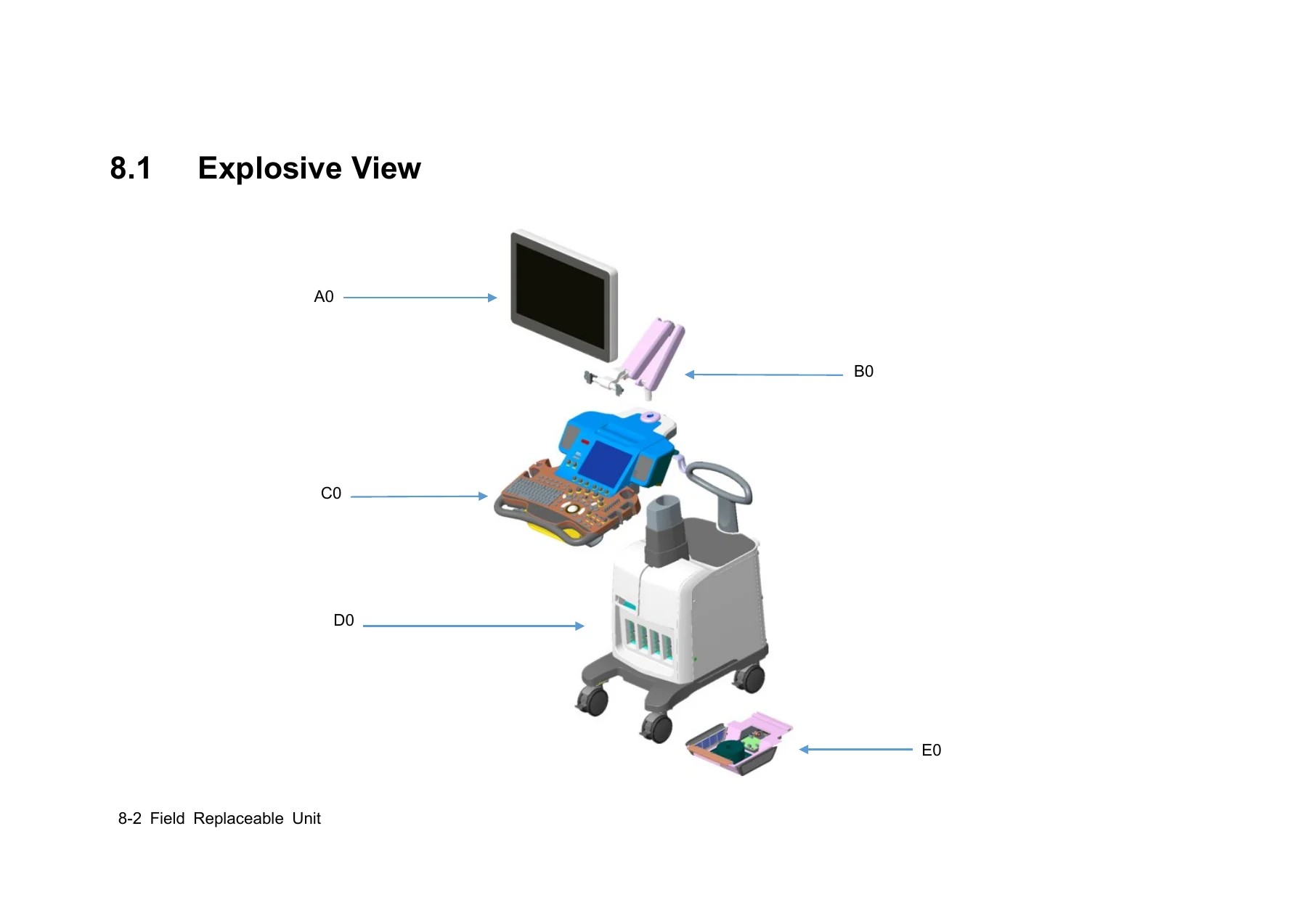
- Field Replaceable Unit — system explosive view; monitor, support arm, main control panel, main unit, power box, and cable assemblies with order numbers
- Structure and Assembly/Disassembly — tools and engineer requirements; connecting board; probe board; hard disk; IO BOX and WIFI PCBA; CW, transmission, receiving, signal processing, and 4D/4D&TEE boards; PC module; DC-DC and AC-DC power; control panel, monitor, minor panel, and related assemblies
- Optional Installation/Assembly — optional software; front USB/ECG and pencil-probe port; 4D module; elastography; CW board; DVR board; battery; gel warmer; WIFI module update
- System Diagnosis and Support — status indicators; AC/BIOS/Windows/Doppler start-up; battery, voltage, temperature, fan, PHV, gel-warmer, and other alarms; maintenance and user self-test and test reports
- Care & Maintenance — tools and consumables; system and peripheral cleaning; general, function, peripheral, mechanical, and electrical safety checks
- Troubleshooting of Regular Malfunctions — no power; no start-up; image display; probe sockets; I/O; control panel; LCD/display; ECG module
- Appendix A Electrical Safety Inspection
- Appendix B Phantom Usage Illustration
- Appendix C Description of Self-diagnosis Test Items
Taken together, those chapters give a technician a map of the cart, the boards that generate and process ultrasound, the replaceable assemblies and order numbers used in the field, the sequence for taking the machine apart and putting it back, and the self-test and fault trees used when the system will not power, boot, image, or talk to a probe or printer.
Cart Layout and Published Specifications
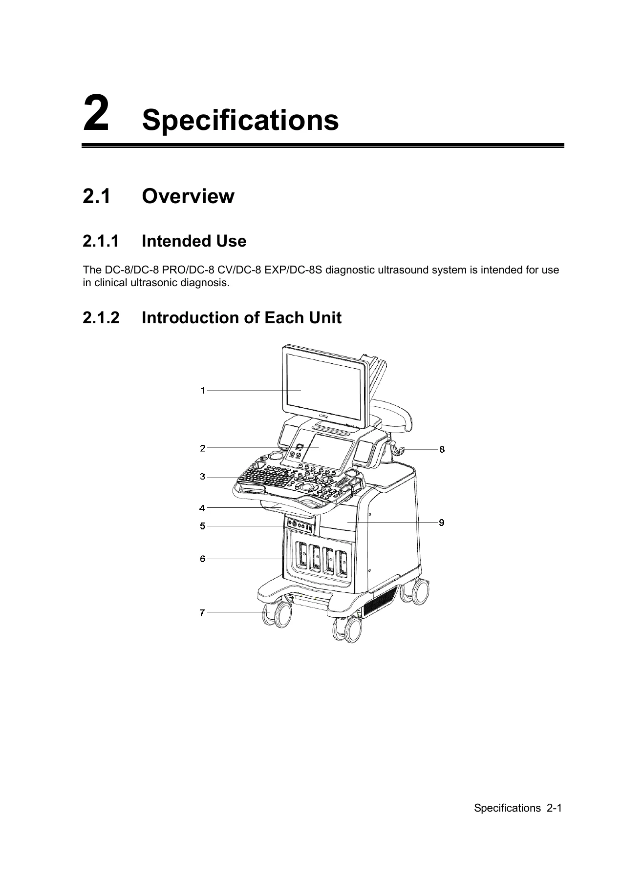
The Mindray DC-8 DC-8 PRO DC-8 CV DC-8 EXP DC-8S Diagnostic Ultrasound Service Manual Revision 23.0 identifies the cart as a wheeled console with a height-adjustable main monitor, touch screen, main control panel, storage compartment, physio panel, probe ports, casters, probe cable hook, B/W printer compartment, monitor support arm, rear handle, color-printer shelf, I/O panel, and power-supply panel. Holders are provided for gel or a gel heater, an endocavity probe, and general / 4D volume probes. A DVD-RW drive and USB/MIC ports sit on the operator side.
Published dimensions are 1355–1800 mm (H) × 930 mm (D) × 585 mm (W). Net weight is about 110 kg. AC input is 220–240 V or 100–127 V at 50/60 Hz with 800 VA power consumption. An optional battery is specified at 11.1 V and 4800 mAh. Operating ambient range is 0°C–40°C, 30%–85% RH (no condensation), 700–1060 hPa; storage and transport allow −20°C–55°C and 30%–95% RH at the same pressure band. The main monitor is 21.5 inch or 23.8 inch at 1920×1080, 12 V, visible angle ≥170. The touch screen is 10.4 inch at 1024×768, 12 V, visible angle ≥170.
The I/O panel documents USB 2.0 ports, 10/100/1000 Mbit Ethernet, DVI-D and HDMI and VGA outputs that follow the main monitor, a standard serial port, a video-printer control port, S-Video and composite paths (several marked reserved), stereo audio, and 3.3 V / 5 V / 12 V power indicators. The power-supply panel carries the equipotential terminal, a peripheral power outlet, circuit breaker, and AC inlet. The physio panel provides ECG lead or external ECG input, PCG input, a pencil-probe port, USB ports, and a reserved port. Control-panel drawings distinguish the DC-8 / DC-8 PRO / DC-8 CV / DC-8S layout from the DC-8 EXP layout and label exam, cursor, B/M/Color/Power/PW/CW, elastography, iScape, 3D/4D, TDI, contrast, cine, and save keys.
Hardware Architecture Used in Service
Chapter 4 is the board-level reference a field engineer needs before swapping FRUs. The front-end unit includes the probe board, CW board, transmission boards A and B, receiving board, signal-processing (DSP) board, front-end analog motherboard, and communication motherboard. The back-end unit includes the digital board, DVR board, IO BOX board, 4D or 4D&TEE board, and back-end motherboard. Separate units cover the control panel, main monitor, touch screen, ECG/PCG, and the power path through the connecting board, AC-DC board, back-end power board, and front-end power board. System monitoring and panel indicators are described in the same chapter so a dark cart or a failed rail can be traced before the covers come off.
Revision notes in this edition also record platform differences that affect parts selection: XP versus Windows 7 PC and digital-board FRUs, 19 inch versus 21.5 inch versus 23.8 inch monitor assemblies, HDD part numbers by region, and the statement that the 4D option does not require a DSP board from software version 02.00.00 onward. Wireless printer support is noted as not available on DC-8 series products later than V4.0. Those notes sit in the revision history and should be checked against the machine in front of you before an FRU is ordered.
Complete PDF Bookmark Tree
Complete Bookmarks
The complete bookmarks in the “Mindray DC-8 DC-8 PRO DC-8 CV DC-8 EXP DC-8S Diagnostic Ultrasound Service Manual Revision 23.0” are as follows:
Table of Contentp. 3
Revision Historyp. 9
Intellectual Property Statementp. 12
Applicable forp. 12
Statementp. 12
Responsibility on the Manufacturer Partyp. 13
Customer Service Departmentp. 13
+1 Safety Precautionsp. 15
1.1 Meaning of Signal Wordsp. 15
+1.2 Symbolsp. 15
1.2.1 Meaning of Safety Symbolsp. 15
1.2.2 Warning Labelsp. 16
1.2.3 General Symbolsp. 16
+1.3 Safety Precautionsp. 17
1.3.1 Electric safetyp. 18
1.3.2 Mechanical safetyp. 18
1.3.3 Personnel Safetyp. 19
1.3.4 Otherp. 19
+2 Specificationsp. 21
+2.1 Overviewp. 21
2.1.1 Intended Usep. 21
+2.1.2 Introduction of Each Unitp. 21
2.1.2.1 I/O panelp. 23
2.1.2.2 Power Supply panelp. 25
2.1.2.3 Physio Panel (ECG & PCG)p. 25
+2.1.2.4 Control Panelp. 26
Exam Operationp. 28
Cursor Operationp. 28
Image operationsp. 29
Parameter Adjustmentp. 31
Measurement, Comment, and Body Mark Operationsp. 32
Other Operationsp. 32
2.1.3 Peripherals Supportedp. 33
+2.2 Specificationsp. 33
2.2.1 Dimensions & Weightp. 33
+2.2.2 Electrical Specificationsp. 33
2.2.2.1 AC Inputp. 33
2.2.2.2 Batteryp. 34
2.2.3 Environmental Conditionsp. 34
+2.2.4 Monitor Specificationp. 34
2.2.4.1 Main Monitorp. 34
2.2.4.2 Touch Screenp. 34
+3 System Installationp. 35
+3.1 Preparations for Installationp. 35
+3.1.1 Electrical Requirementsp. 35
3.1.1.1 Requirement of Regulated Power Supplyp. 35
3.1.1.2 Grounding Requirementsp. 35
3.1.1.3 EMI Limitationp. 35
+3.1.2 Installation Conditionsp. 36
3.1.2.1 Space Requirementsp. 36
3.1.2.2 Networking Pre-installation Requirementsp. 36
3.1.3 Confirmation before Installationp. 37
+3.2 Unpackingp. 37
3.2.1 Unpackingp. 37
3.2.2 Notice of Packingp. 39
3.2.3 Checkingp. 40
+3.3 Installation of Main Unitp. 40
3.3.1 Open up the Monitorp. 40
3.3.2 Connecting the Power Cordp. 40
3.3.3 Connecting ECGp. 41
3.3.4 Install Endocavity probe bracketp. 41
+3.3.5 Connecting the Transducerp. 42
3.3.5.1 Using the Probe Dust-proof Coverp. 42
+3.4 Installing Peripheralsp. 42
3.4.1 Connecting the Footswitchp. 42
3.4.2 Installing a Graph / Laser Printerp. 43
+3.4.3 Installing Video Printerp. 43
3.4.3.1 Analog Video Printerp. 43
3.4.3.2 Digital Video Printerp. 45
3.4.3.3 Wireless Printerp. 45
3.4.4 Installing Barcode Scannerp. 45
+3.5 System Configurationp. 47
3.5.1 Running the Systemp. 47
3.5.2 Enter into DOPPLERp. 47
3.5.3 System Presetp. 47
3.5.4 Print Presetp. 48
3.5.5 Network Presetp. 50
3.5.6 DICOM Presetp. 51
3.5.7 Check System Informationp. 53
+4 Product Principlep. 55
4.1 General Structure of Hardware Systemp. 55
+4.2 Ultrasound Front-end Unitp. 56
4.2.1 Probe Boardp. 57
4.2.2 CW Boardp. 58
4.2.3 Transmission Boardp. 58
4.2.4 Receiving Boardp. 59
4.2.5 Signal Processing Boardp. 59
4.2.6 Front-end Analog Mother Boardp. 61
4.2.7 Communication Mother Boardp. 62
+4.3 Ultrasound Back-end Unitp. 63
4.3.1 Digital Boardp. 63
4.3.2 DVR Boardp. 65
4.3.3 IO BOX Boardp. 66
4.3.4 4D or 4D&TEE boardp. 67
4.3.5 Back-end Motherboard Connectionp. 67
4.3.6 Ultrasound System Monitoringp. 68
4.3.7 Indicators on the Ultrasound Systemp. 69
4.4 Control Panel Unitp. 69
4.5 ECG&PCG Unitp. 70
4.6 Main Monitor Unitp. 71
4.7 Touch Screen Unitp. 72
+4.8 Power Supply Unitp. 72
4.8.1 Connecting Boardp. 73
4.8.2 AC-DC Power Boardp. 74
4.8.3 Back-end Power Boardp. 75
+4.8.4 Front-end Power Boardp. 75
4.8.4.1 Front-end Power Main Boardp. 76
4.8.4.2 Front-end Power Auxiliary Boardp. 76
4.8.5 Power and the Supported Functions Distributionp. 77
4.8.6 System power on controlp. 79
+5 Function and Performance Checking Methodp. 81
5.1 Notep. 81
+5.2 System Running Statusp. 81
5.2.1 Running Statusp. 81
5.2.2 Working Conditionp. 81
+5.3 General examp. 82
5.3.1 Check Flowp. 82
+5.3.2 Checking Contentp. 82
5.3.2.1 Check Control Panelp. 82
5.3.2.2 Check the Monitorp. 82
5.3.2.3 Check Touch Panelp. 83
5.3.2.4 Check DVD-R/Wp. 83
5.3.2.5 Check Peripheralsp. 83
5.3.2.6 Check ECG Modulep. 84
5.3.2.7 Check I/O Portsp. 84
+5.4 Function Checkingp. 84
5.4.1 Checking Flowp. 85
+5.4.2 Contentp. 85
5.4.2.1 Imaging Modesp. 85
1. B modep. 85
2. M modep. 86
3. Color modep. 86
4. Power modep. 87
5. PW/CW modep. 87
5.4.2.2 Basic Measurementsp. 87
5.4.2.3 Cine Reviewp. 88
5.4.2.4 Probe Switchingp. 89
5.4.2.5 Patient Information Managementp. 89
+5.5 Performance Testp. 90
5.5.1 Test Processp. 90
+5.5.2 Test Contentp. 90
5.5.2.1 Resolutionp. 90
5.5.2.2 Maximum Depthp. 92
5.5.2.3 Geometric positioning accuracyp. 94
5.5.2.4 Blackout Areap. 96
+6 Software Installation &Maintenancep. 97
6.1 Enter into Maintenancep. 97
6.2 Software Installation/Restorationp. 98
6.3 Enter into Windowsp. 98
+6.4 Software maintenancep. 99
6.4.1 Product Configurationp. 99
+6.4.2 Log Maintenancep. 99
6.4.2.1 Export the Logp. 99
6.4.2.2 Upload Logp. 100
6.4.3 Remote Desktopp. 100
+6.5 Data Backup and Storagep. 101
+6.5.1 Manage Settingsp. 101
6.5.1.1 Back up the Preset Datap. 102
6.5.1.2 Restore the Preset Datap. 102
+6.5.2 Patient Data Backup and Restorep. 102
6.5.2.1 Patient Data Backupp. 102
6.5.2.2 Restore Patient Datap. 102
6.6 HDD Partitionp. 102
+7 Adjustmentsp. 105
+7.1 Monitor Adjustmentp. 105
7.1.1 Position Adjustmentp. 105
7.1.2 Brightness and Contrast Adjustmentp. 106
7.1.3 Monitor Testp. 107
7.1.4 Monitor Parameter Settingp. 108
+7.2 Touch Screen Adjustmentp. 109
7.2.1 Touch Screen Brightness and Contrast Adjustmentp. 109
7.2.2 Touch Screen Calibrationp. 109
7.2.3 Touch Screen Testp. 110
7.2.4 Touch Screen Settingp. 110
7.3 Control Panel Adjustmentp. 110
7.4 Caster Adjustmentp. 111
+8 Field Replaceable Unitp. 113
8.1 Explosive Viewp. 114
+8.2 Assembly Explosive Viewp. 115
8.2.1 Monitor Assembly (A0)p. 115
8.2.2 Monitor Support Arm Assembly (B0)p. 116
8.2.3 Main Control Panel Assembly (C0)p. 117
8.2.4 Main Unit Assembly (D0)p. 124
8.2.5 Power Box Assembly (E0)p. 138
8.2.6 Cable Assembly (F0)p. 139
+9 Structure and Assembly/Disassemblyp. 141
9.1 Structure of the Whole Systemp. 141
+9.2 Preparationp. 141
9.2.1 Tools Requiredp. 141
9.2.2 Requirement for Engineersp. 141
9.2.3 Assembly/Disassembly Requirementsp. 141
+9.3 Assembly and Disassemblyp. 141
9.3.1 Connecting Boardp. 142
9.3.2 Remove Probe Board Assemblyp. 143
9.3.3 Hard Disk Assemblyp. 145
9.3.4 IO BOX Board and WIFI PCBAp. 147
9.3.5 CW Board, Transmission Board, Receiving Board, Signal Processing Board and 4D or 4D&TEE boardp. 149
+9.3.6 PC Module Assemblyp. 151
9.3.6.1 Digital Board Assembly (XP)p. 151
9.3.6.2 Digital Board Assembly and COME module assembly (Win7)p. 152
9.3.6.3 DVR Boardp. 154
+9.3.7 DC-DC Power Modulep. 155
9.3.7.1 Front-end Power Assistant Boardp. 155
9.3.7.2 Back-End Power Boardp. 155
9.3.7.3 Front-end Power Main Boardp. 156
9.3.8 AC-DC Power Boardp. 156
+9.3.9 Control Panel Assemblyp. 157
9.3.9.1 Master panel Six in One Encoder Assemblyp. 158
9.3.9.2 ZOOM Encoder assemblyp. 159
9.3.9.3 NAVI Encoder Assemblyp. 160
9.3.9.4 TGC Assemblyp. 160
9.3.9.5 Trackball Assemblyp. 161
9.3.9.6 Digital Keyboard Module (for XP)p. 162
9.3.9.7 Digital Keyboard Module (for Win7)p. 163
9.3.9.8 Keyboard Board and Silicon Key/1 of Main Control Keyboardp. 163
+9.3.10 Monitor Assemblyp. 164
9.3.10.1 Monitor Assembly\Front Cover Assembly\ Back Coverp. 165
9.3.10.2 Replace Front Cover Assemblyp. 165
9.3.10.3 Control Boardp. 166
+9.3.11 Minor Panel Assemblyp. 166
9.3.11.1 10.4 inch Display Assemblyp. 168
9.3.11.2 10.4 inch LCD Screen Control Boardp. 168
9.3.11.3 Touch Screen Modulep. 168
9.3.11.4 Minor Panel Six in One Encoder Modulep. 169
9.3.11.5 Minor Keyboard Module, Power Silicon Keyp. 170
+9.3.12 Othersp. 171
9.3.12.1 Fanp. 171
9.3.12.2 DVD-R/Wp. 172
9.3.12.3 Speaker assemblyp. 173
9.3.12.4 Disassembly of Gas spring Assemblyp. 174
9.3.12.5 Supporting Arm Assembly of Monitorp. 184
+10 Optional Installation/Assemblyp. 193
10.1 Installing Optional Softwarep. 193
+10.2 Installing Optional Hardwarep. 195
+10.2.1 Front Board USB&ECG and Pencil Probe Port Assemblyp. 196
If the pencil probe silk print is on the leftmost position (as depicted below), please change the entire assembly by the procedures described in 10.2.1 chapter.p. 198
If the pencil probe silk print is on the position as depicted below, please install the pencil probe outlet and cable by the following procedure.p. 199
+10.2.2 4D Modulep. 204
10.2.2.1 4D or 4D&TEE board and Signal Processing Board (supporting 4D/elastography)p. 204
10.2.2.2 4D or 4D&TEE boardp. 206
10.2.3 Elastographyp. 206
10.2.4 CW Boardp. 207
10.2.5 DVR Boardp. 207
10.2.6 Battery Assemblyp. 208
10.2.7 Gel Warmerp. 209
10.2.8 WIFI Module Updatep. 210
+11 System Diagnosis and Supportp. 213
+11.1 General Status Indicatorp. 213
11.1.1 The Status Indicators of the Control Panelp. 213
11.1.2 The Status Indicator of the Power on the IO Rear Boardp. 214
11.1.3 Monitor Status Indicatorp. 214
11.1.4 The Status of Whole Machinep. 214
11.1.5 Status Indicator of Gel Warmerp. 215
+11.2 Start-up Process of the Whole Systemp. 216
11.2.1 Complete System AC Power on processp. 216
11.2.2 BIOS Start-up Processp. 217
11.2.3 Windows Start-up Processp. 217
+11.2.4 Doppler Start-up Processp. 217
11.2.4.1 Start-up Processp. 217
11.2.4.2 Detailsp. 218
+11.3 Warning and Abnormal Informationp. 219
11.3.1 Battery Alarmp. 220
11.3.2 The Voltage of System Power Alarmp. 220
11.3.3 Temperature Alarmp. 220
11.3.4 Fan Alarmp. 221
11.3.5 PHV Alarmp. 222
11.3.6 Gel Warmer Abnormalityp. 222
11.3.7 Other Alarmsp. 223
+11.4 Self-testp. 224
11.4.1 Introductionp. 224
11.4.2 Maintenance Self-testp. 224
11.4.3 User Self-testp. 229
+11.4.4 Test Reportp. 230
11.4.4.1 Test Formsp. 230
11.4.4.2 Save the Test Datap. 231
11.4.4.3 Export the Test Datap. 231
+12 Care & Maintenancep. 233
+12.1 Overviewp. 233
12.1.1 Tools, Measurement Devices and Consumablesp. 233
12.1.2 Care and Maintenance Itemsp. 233
+12.2 Cleaningp. 235
+12.2.1 Clean the Systemp. 235
12.2.1.1 Flow of Cleaningp. 235
12.2.1.2 Contentp. 235
12.2.2 Clean the Peripheralsp. 238
+12.3 Checkingp. 239
12.3.1 General checkp. 239
12.3.2 System Function Checkp. 240
12.3.3 Peripherals and Options Checkp. 241
12.3.4 Mechanical Safety Inspectionp. 241
12.3.5 Electrical Safety Inspectionp. 243
+13 Troubleshooting of Regular Malfunctionsp. 245
+13.1 Troubleshooting When System Can’t Be Powered onp. 245
13.1.1 Module or Board Relatedp. 245
13.1.2 Key Points Supporting Troubleshootingp. 245
13.1.3 Troubleshooting When System Can’t Be Powered onp. 245
+13.2 Troubleshooting When System cannot be started upp. 246
13.2.1 Module or Board Relatedp. 246
13.2.2 Key Points Supporting Troubleshootingp. 246
13.2.3 Troubleshooting When System cannot be Startedp. 247
+13.3 Troubleshooting for Image Displayingp. 247
13.3.1 Module or Board Relatedp. 247
13.3.2 Key Points Supporting Troubleshootingp. 247
13.3.3 Troubleshooting for Image Displayingp. 248
+13.4 Probe Socket System Related Malfunction Troubleshootingp. 249
13.4.1 Module or Board Relatedp. 249
13.4.2 Key Points Supporting Troubleshootingp. 249
13.4.3 Probe Socket System Related Malfunction Troubleshootingp. 249
+13.5 IO System Related Malfunction Troubleshootingp. 250
13.5.1 Module or Board Relatedp. 250
13.5.2 Key Points Supporting Troubleshootingp. 250
13.5.3 IO System Related Malfunction Troubleshootingp. 250
+13.6 Control Panel Malfunction Troubleshootingp. 251
13.6.1 Module or Board Relatedp. 251
13.6.2 Key Points Supporting Troubleshootingp. 252
13.6.3 Control Panel Malfunction Troubleshootingp. 252
+13.7 LCD and Display Malfunction Troubleshootingp. 253
13.7.1 Module or Board Relatedp. 253
13.7.2 Key Points Supporting Troubleshootingp. 253
13.7.3 Display Related Troubleshootingp. 253
+13.8 ECG Module Related Troubleshootingp. 254
13.8.1 Module or Board Relatedp. 254
13.8.2 Key Points Supporting Troubleshootingp. 254
+13.8.3 ECG module Related Troubleshootingp. 254
Appendix A Electrical Safety Inspectionp. 257
Appendix B Phantom Usage Illustrationp. 275
+Appendix C Description of Self-diagnosis Test Itemsp. 277
C.1.1 Z0101 Hard Disk Verifyp. 277
C.1.2 Z0201 PC Module Heat Sink Testp. 277
C.1.3 Z0301 PC Module and MF FPGA Interconnection Testp. 278
C.1.4 Z0302 SVIDEO Buffer DDRII Testp. 278
C.1.5 Z0303 MF FPGA and System Monitor Interconnection Testp. 279
C.1.6 Z0304 Fan Speed Monitor Testp. 279
C.1.7 Z0305 System Temperature Testp. 279
C.1.8 Z0306 System Voltage Testp. 280
C.1.9 Z0307 Speaker Testp. 280
C.1.10 Z0308 CP210x Serial Number Testp. 281
C.1.11 Z0309 Serial Port Testp. 282
C.1.12 Z0310 Microphone Interface Testp. 282
C.1.13 Z0401 MF and Front Power Main Board ARM Interconnection Testp. 282
C.1.14 Z0402 Front Power Main Board Function Testp. 283
C.1.15 Z0501 MF and Back-End Power ARM Interconnection Testp. 283
C.1.16 Z0502 Battery I2C Interconnection Testp. 284
C.1.17 Z0601 LCD Monitor I2C Connection Testp. 284
C.1.18 Z0602 Touch Screen LCD Monitor I2C Connection Testp. 285
C.1.19 Z0701 Keyboard USB Interconnection Testp. 285
C.1.20 Z0702 Keyboard Key, Encoder, TGC, Trackball Function Testp. 285
C.1.21 Z0703 Keyboard Key and Trackball LED Testp. 288
C.1.22 Z0801 PC Module and DSP Interconnection Testp. 289
C.1.23 Z0802 DSP DDR Testp. 289
C.1.24 Z0901 Transmitter Board A Slot ID Testp. 290
C.1.25 Z0902 Transmitter Board A and DSP Board Interconnection Testp. 290
C.1.26 Z1001 Transmitter Board B Slot ID Testp. 290
C.1.27 Z1002 Transmitter Board Band DSP Board Interconnection Testp. 291
C.1.28 Z1101 BF1 FPGA and DSP FPGA Interconnection Testp. 291
C.1.29 Z1102 BF1 FPGA and BF2 FPGA Interconnection Testp. 291
C.1.30 Z1103 BF and DSP Interconnection Test (Data Interface)p. 292
C.1.31 Z1104 ATGC Function Testp. 292
C.1.32 Z1105 AFE Digital Interface Testp. 293
C.1.33 Z1106 Transmission and Reception Function Testp. 293
C.1.34 Z1201 Probe Board and Receiver Board Interconnection Testp. 293
C.1.35 Z1301 CW Board and DSP Board Interconnection Testp. 294
C.1.36 Z1302 CW and DSP Interconnection Test (Data Interface)p. 294
C.1.37 Z1303 CW SPI Testp. 294
C.1.38 Z1304 CW AFE Digital Interface Testp. 295
C.1.39 Z1305 CW ATGC Function Testp. 295
C.1.40 Z1306 CW IQ Testp. 295
C.1.41 Z1401 4D Driver Board ID Testp. 295
C.1.42 Z1402 4D Driver Board Driver Circuit Testp. 296
C.1.43 Z1403 4D Driver Board Programmable Voltage Testp. 296
C.1.44 Z1501 ECG Module Information Read Testp. 296
C.1.45 Z1502 ECG Module Self Testp. 297
Installation, Options, and Software Work
Installation chapters specify a three-wire grounded supply, a quality regulator or on-line UPS where mains are unstable, at least 20 cm clearance for cooling, a door at least 0.8 m wide, and spare receptacles for peripherals. EMI sources such as electrosurgical units, phones, and radios are called out as installation risks. Wired and wireless LAN plus DICOM server name, port, and IP data are collected before network preset. After power-up the manual walks Doppler entry, system preset, print preset, network preset, DICOM preset, and the Setup-About system-information page.
Optional hardware procedures cover the front USB/ECG and pencil-probe port assembly, 4D module, elastography, CW board, DVR board, battery assembly, gel warmer, and WIFI module update (with OS version gates). Software chapters cover entering maintenance, OS and Doppler restoration, a restore-package checking tool added in later revisions, product configuration, log maintenance, remote desktop, patient-data backup and restore, and HDD partitioning as revised in later editions.
Diagnosis, Self-Test, and Fault Isolation
Status indicators are defined for the control panel, IO rear-board power lamps, monitor, whole-machine state, and gel warmer. Start-up is split into complete AC power-on, BIOS, Windows, and Doppler phases so a hang can be localized. Alarm text is listed for battery, system power voltage, temperature, fan, PHV, gel-warmer abnormality, and other conditions. Maintenance self-test, user self-test, and the test-report format are documented, with Appendix C describing individual self-diagnosis items (expanded across revisions to include items C.1.21–C.1.46 and later additions).
Chapter 13 then walks regular malfunctions by subsystem: no AC power, no start-up including an “OPERATING SYSTEM NOT FOUND” path that points at HDD or OS root damage, image-display faults, probe-socket faults, I/O and printer-control faults, control-panel faults, LCD and display faults, and ECG-module faults. Each section names related modules or boards and the key points used to decide whether to reseat a cable, replace a board, or restore software. Appendix A is the electrical safety inspection; Appendix B illustrates phantom use for performance checks.
Disassembly Discipline and Care
Assembly and disassembly chapters list required tools, engineer qualifications, and handling rules, including the electric-safety warning that other cables must be seated before the battery cable is connected to avoid hot-plug damage. Procedures cover the connecting board, probe-board assembly, hard-disk assembly, IO BOX and WIFI PCBA, the front-end imaging boards and 4D/TEE board, PC module (with EXP/Win7 versus XP step splits recorded in later revisions), DC-DC module, AC-DC board, control panel (including digital keyboard steps for DC-8 EXP), monitor (including front-cover order number added in Revision 8.0), minor panel, gas spring, and monitor support arm. Care chapters add cleaning methods for the system and peripherals plus scheduled general, functional, mechanical, and electrical inspections.
Get the Manual and Start the Job
With the Mindray DC-8 DC-8 PRO DC-8 CV DC-8 EXP DC-8S Diagnostic Ultrasound Service Manual Revision 23.0 a trained technician can unpack and site the cart, configure network and DICOM, identify and order FRUs from the explosive views, replace front-end and back-end boards, restore OS and Doppler software, run self-tests, and follow the documented trees for power, boot, image, probe, I/O, panel, display, and ECG failures. Following the published voltages, environmental limits, torque-free handling rules, and board-level procedures reduces the chance of leakage-current faults, hot-plug damage, or a mis-ordered monitor or PC module. After payment the file is delivered as an instant PDF download — no shipping delay — ready to open on a service laptop or print selected chapters for the bench.

Reviews
There are no reviews yet.