Mitsubishi FB13-20PNT FB16-20PN Forklift FC/MC Controller Service Manual 2012
$39.95 Original price was: $39.95.$23.95Current price is: $23.95.
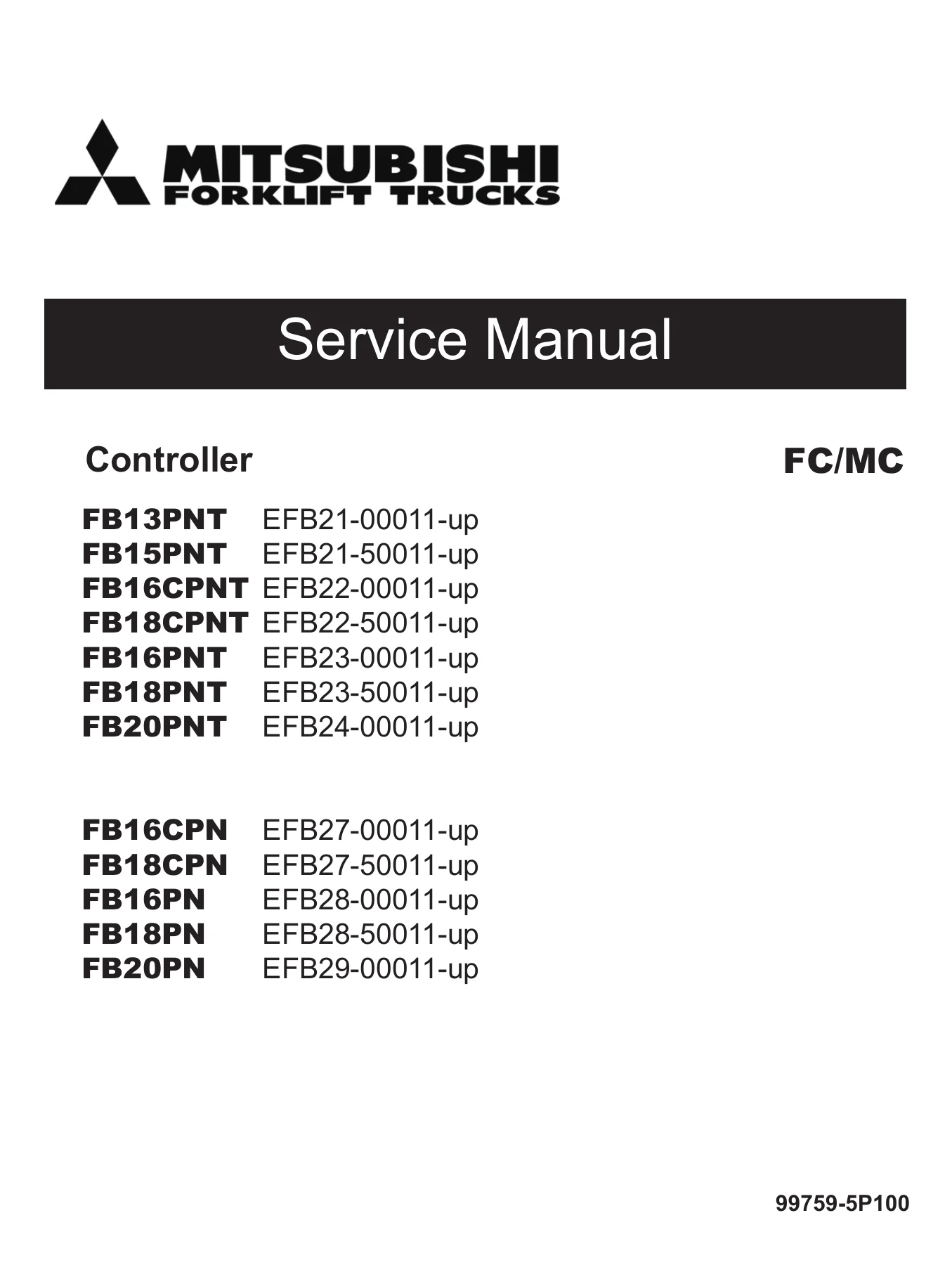
Complete controller service manual for Mitsubishi FB13-20PNT and FB16-20PN forklift trucks with FC/MC control systems. Covers diagnostics, troubleshooting, motor service, circuit diagrams, setup options, and more. Document 99759-5P100, 2012.
Description
File Details
- Manual Type: Controller Service Manual
- Brand: Mitsubishi Forklift Trucks
- Models Covered: FB13PNT, FB15PNT, FB16CPNT, FB18CPNT, FB16PNT, FB18PNT, FB20PNT, FB16CPN, FB18CPN, FB16PN, FB18PN, FB20PN
- Language: English
- Page Count: 294
- File Format: PDF
- Document Number: 99759-5P100
- Date: 2012
Chapters Covered
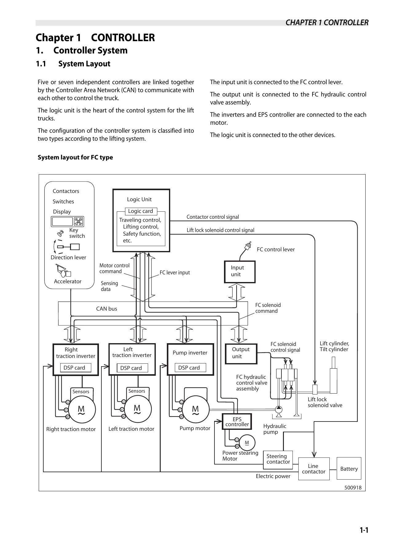
- Controller System
- System Layout
- Controller Area Network (CAN)
- Logic Unit
- Inverter
- EPS Controller
- Input Unit
- Output Unit
- Traction Controller Features
- Modification of Traction Characteristics
- Anti-Rollback
- Boost
- Limitation of Maximum Travel Speed
- Controlled Cornering Speed
- Pitching Control
- Lifting Controller Features
- Lift Work Speed Settings
- Lift Stop
- Load Meter
- Tilt Horizon
Complete PDF Bookmark TreeComplete Bookmarks
The complete bookmarks in the βMitsubishi FB13-20PNT FB16-20PN Forklift FC/MC Controller Service Manual 2012β are as follows:
COVERp. 1+FOREWORDp. 3
1. Safetyp. 4+2. How to Use This Manualp. 5
2.1 Truck Modelp. 5+3. Unitsp. 6
Chapter 1 CONTROLLERp. 7Chapter 2 TROUBLESHOOTING FOR CONTROL CIRCUITSp. 8Chapter 3 MOTORp. 10Chapter 4 HOW TO READ CIRCUIT DIAGRAMSp. 11Chapter 5 CIRCUIT DIAGRAMp. 11TABLE OF CONTENTSp. 7+Chapter 1 CONTROLLERp. 13
+1. Controller Systemp. 13
1.1 System Layoutp. 131.2 Controller Area Network (CAN)p. 151.3 Outline of Logic Unitp. 161.4 Outline of Inverterp. 191.5 Outline of EPS Controllerp. 201.6 Outline of Input unitp. 211.7 Outline of Output unitp. 22+2. Traction Controller Featurep. 23
2.1 Modification of traction characteristicsp. 232.2 Unti-rollbackp. 232.3 Boostp. 242.4 Limitation of maximum travel speedp. 242.5 Controlled Cornering Speedp. 252.6 Miscellaneous features for tractionp. 252.7 Pitching Control (Option)p. 26+3. Lifting Controller Featurep. 27
3.1 Setting and limitation of lift work speedp. 273.2 Lift stopp. 273.3 Load meter (option)p. 283.4 Tilt horizon (option)p. 28+4. Other Featurep. 29
4.1 IPS (Integrated Presence System) featurep. 294.2 Display functionp. 314.3 Parking Brake Interlockp. 324.4 BDI (Battery discharge indicator) display featuresp. 324.5 Miscellaneous featuresp. 324.6 Hour Meterp. 33+5. Setup Optionp. 34
5.1 Outlinep. 345.2 Details of Setup Options (Group-1)p. 355.3 Details of Setup Options (Group-2)p. 395.4 Details of Setup Options (Group-3)p. 445.5 Setup Options (Group 1)p. 475.6 Setup Options (Group 2)p. 485.7 Setup Options (Group 3)p. 50+6. Diagnosticsp. 51
6.1 Outlinep. 516.2 Operation Procedurep. 516.3 Self-Diagnosticsp. 536.4 Power Steering Diagnosticsp. 546.5 Run Time Diagnosticsp. 566.6 Fail-Safe Restriction Listp. 63+7. Removal and Installationp. 65
7.1 Inverter Discharging Procedurep. 657.2 Replacing Inverterp. 667.3 Replacing DSP (Digital Signal Processor) Cardp. 677.4 Replacing Logic Unitp. 697.5 Replacing EPS Controllerp. 707.6 Replacing Logic Cardp. 717.7 Replacing Power Supply Cardp. 727.8 Replacing Input Unit (FC MODEL ONLY)p. 737.9 Replacing Output Unit (FC MODEL ONLY)p. 74+8. Basic Checkp. 75
8.1 Testing Toolsp. 758.2 Measurement of Card Voltagep. 758.3 Checking Contactor Coilp. 828.4 Checking Contactor Tipsp. 828.5 Checking Inverterp. 838.6 Regeneration Checkp. 83+9. AC Motor System Basicsp. 84
9.1 Feature of AC motorp. 849.2 Speed control of induction motorsp. 849.3 Inverterp. 85+Chapter 2 TROUBLESHOOTING FOR CONTROL CIRCUITSp. 87
+1. General Informationp. 87
1.1 Before replacing devicesp. 871.2 Connection of the service toolp. 871.3 How to clean harness connectors and system componentsp. 882. List of Error Codesp. 89+3. Troubleshootingp. 90
3.1 Traction Motor R.H.,Overheating (E0)p. 903.2 Traction Motor L.H.,Overheating (E1)p. 933.3 Pump Motor,Overheating(E2)p. 963.4 Traction Inverter R.H., Overheating (E5)p. 993.5 Traction Inverter L.H., Overheating (E6)p. 1023.6 Pump Inverter, Overheating (E7)p. 1053.7 PS Controller,Overheating (E9)p. 1083.8 Traction Motor Current Sensor R.H., Fault (14)p. 1113.9 Traction Motor R.H., Over-current (15)p. 1133.10 Traction Motor R.H., Stall Timer (16)p. 1163.11 Traction Motor Current Sensor L.H., Fault (24)p. 1183.12 Traction Motor L.H., Over-current (25)p. 1203.13 Traction Motor L.H., Stall Timer (26)p. 1233.14 Pump Motor Current Sensor Fault (34)p. 1253.15 Pump Motor Over-current (35)p. 1273.16 Line Contactor Fault (40)p. 1293.17 Steering Contactor Fault (41)p. 1323.18 Traction Motor R.H., Open (45)p. 1343.19 Traction Motor L.H., Open (46)p. 1363.20 Pump Motor Open (47)p. 1383.21 PS Motor Open (49)p. 1403.22 Tire Angle Sensor Fault (50)p. 1423.23 Accelerator Sensor Fault (51)p. 1443.24 Traction Motor R.H., Pulse Input Fault (52)p. 1463.25 Traction Motor L.H., Pulse Input Fault (53)p. 1483.26 FC Lever Fault (54)p. 1503.27 Output Unit Solenoid Fault (55)p. 1523.28 Output Unit Solenoid Current Leak (56)p. 1543.29 FNR Lever or Accelerator, Faulty Setting (E)p. 1563.30 Seat Switch, Faulty Setting for Traction ((E))p. 1583.31 Lift Lever, Faulty Setting (H1)p. 1603.32 Tilt Lever, Faulty Setting (H2)p. 1623.33 Attachment 1 Lever, Faulty Setting (H3)p. 1643.34 Attachment 2 Lever, Faulty Setting (H4)p. 1663.35 Seat Switch, Faulty Setting for Hydraulic ((L))p. 1683.36 FNR Lever Fault (EE)p. 1703.37 Display Communication Fault (60)p. 1723.38 Logic Card Initialize Failure (61)p. 1743.39 Logics Fault (62)p. 1753.40 Traction Inverter R.H., Fault (63)p. 1763.41 Traction Inverter L.H., Fault (64)p. 1793.42 Pump Inverter Fault(65)p. 1823.43 Input Unit Fault (67)p. 1853.44 Output Unit Fault (68)p. 1873.45 EPS Controller Fault (71)p. 1893.46 Contactor Coil Fault (72)p. 1923.47 Hydraulic Lock Solenoid Fault (74)p. 1943.48 Parking Brake Fault (75)p. 1963.49 IPS Buzzer Fault (76)p. 1983.50 Battery Voltage Too Low (78)p. 2003.51 Battery Voltage Too High (79)p. 2023.52 Battery Consumption Too Much (Lo)p. 2043.53 Tilt Angle Sensor Fault (80)p. 2063.54 Load Sensor Fault (81)p. 2083.55 Handle Sensor Fault (82)p. 2103.56 PS Motor Current Sensor Fault (A4)p. 2123.57 PS Motor Over-current (A5)p. 2143.58 PS Handle Brake Fault (A7)p. 2163.59 Battery Side Way Exchange Interlock (A8)p. 2183.60 Parking brake warning (A9)p. 2203.61 Much Battery Consumptionp. 2223.62 Brake Oil, Low Levelp. 2243.63 RTC Battery Lowp. 226+Chapter 3 MOTORp. 227
1. Motor Installation Positionsp. 2272. Specificationsp. 229+3. Structuresp. 230
3.1 Traction motorp. 2303.2 Pump motorp. 2313.3 EPS motorp. 2324. Removing Transfer Assemblies, Traction motorsp. 233+5. Disassembling Traction motorp. 234
5.1 Disassembly Sequencep. 234+6. Inspecting Traction Motorp. 235
6.1 Inspecting Rotorp. 2356.2 Inspecting Motorp. 2366.3 Inspection of insulationp. 236+7. Resassembling Traction motorp. 237
7.1 Resassembly Sequencep. 237+8. Removing Pump Motorp. 238
8.1 Suggestions for Removalp. 238+9. Disassembing Pump Motorp. 240
9.1 Disassembly Sequencep. 240+10. Inspecting Pump Motorp. 241
10.1 Inspecting Rotorp. 24110.2 Inspecting Motorp. 24110.3 Inspection of insulationp. 241+11. Resassembling Pump motorp. 242
11.1 Resassembly Sequencep. 24212. Tightening of High-power Cable Terminalsp. 243+13. Removing EPS Motorp. 244
13.1 Suggestions for Removalp. 24414. Disassembling EPS Motorp. 244+15. Inspecting EPS Motorp. 246
15.1 Inspecting Armaturep. 24615.2 Inspecting Motorp. 24815.3 Inspecting Oil Seal and Permanent Magnetp. 249+16. Inspecting EPS Motorp. 250
16.1 Brushp. 25017. Troubleshootingp. 251+Chapter 4 HOW TO READ CIRCUIT DIAGRAMSp. 253
+1. Description of Circuit Diagramsp. 253
1.1 Schematic diagramp. 2531.2 Connector Diagramsp. 253+2. How to Read Circuit Diagramsp. 254
2.1 Symbolsp. 2552.2 Sheet Symbolp. 2582.3 Connecting Linesp. 2592.4 Equipmentp. 2602.5 Relay Contactor and Coilp. 2612.6 Connectorsp. 2612.7 Indication of Connecting Linep. 2622.8 Indication of GND (Earth)p. 2622.9 Indication of Another Specificationp. 2633. How to Read Connector Diagramsp. 264Chapter 5 CIRCUIT DIAGRAMp. 267Back coverp. 293Rear coverp. 294 - Other Features
- IPS (Integrated Presence System)
- Display Function
- Parking Brake Interlock
- BDI Display
- Hour Meter
- Setup Options
- Group 1 (Basic Function)
- Group 2 (Detailed Function)
- Group 3 (Model Information)
- Diagnostics
- Self-Diagnostics
- Power Steering Diagnostics
- Run Time Diagnostics
- Fail-Safe Restriction List
- Removal and Installation
- Inverter Discharging Procedure
- Replacing Inverter
- Replacing DSP Card
- Replacing Logic Unit
- Replacing EPS Controller
- Replacing Logic Card
- Replacing Power Supply Card
- Replacing Input Unit (FC Model)
- Replacing Output Unit (FC Model)
- Basic Check
- Testing Tools
- Measurement of Card Voltage
- Checking Contactor Coil
- Checking Contactor Tips
- Checking Inverter
- Regeneration Check
- AC Motor System Basics
- Feature of AC Motor
- Speed Control of Induction Motors
- Inverter
- Troubleshooting for Control Circuits
- List of Error Codes
- Troubleshooting by Error Code
- Detailed Diagnostic Procedures
- Motor
- Motor Installation Positions
- Specifications
- Structures
- Removing Transfer Assemblies, Traction Motors
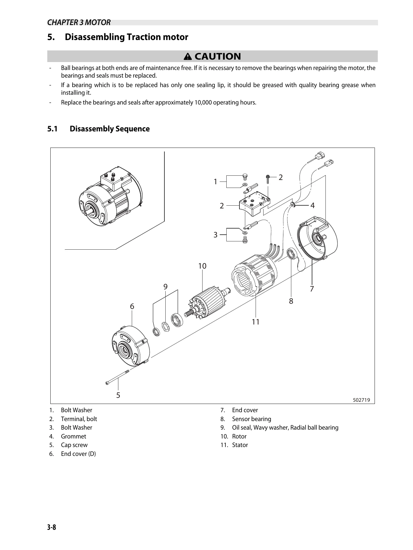
- Disassembling Traction Motor
- Inspecting Traction Motor
- Reassembling Traction Motor
- Removing Pump Motor
- Disassembling Pump Motor
- Inspecting Pump Motor
- Reassembling Pump Motor
- Removing EPS Motor
- Disassembling EPS Motor
- Inspecting EPS Motor
- Troubleshooting
IMAGES PREVIEW
- How to Read Circuit Diagrams
- Schematic Diagram
- Connector Diagrams
- Symbols
- Equipment Numbering
- Connectors
- Circuit Diagram
This Mitsubishi FC/MC Controller Service Manual is the complete technical guide for the controller system used in FB13-20PNT and FB16-20PN series forklift trucks. It covers five or seven independent controllers linked by a Controller Area Network (CAN), the logic unit at the heart of the control system, and the inverters and EPS controller that drive each motor. The manual walks through every stage of controller operation β from system layout and communication protocols to detailed setup options and diagnostic procedures.
Inside, you’ll find complete troubleshooting procedures for every error code the controller can display, from traction motor overheating (E0, E1) and inverter faults (E5, E6, E7) to current sensor faults (14, 24, 34), contactor faults (40, 41), and sensor issues (50, 51, 80, 81, 82). Each error code section includes the fault condition, possible causes, step-by-step checks with connector references, and the correct repair procedure. The Run Time Diagnostics table lists every error code with its display icon, restriction, and recovery method, so you can quickly identify what the truck is telling you.
The manual also provides complete removal and installation procedures for the inverter, DSP card, logic unit, EPS controller, logic card, power supply card, input unit, and output unit β with all required discharge procedures for the inverters before working on the electrical system. Basic check procedures cover testing tools, card voltage measurement with pin-by-pin voltage charts for the logic card, power supply card, DSP cards, input unit, output unit, and EPS controller, plus contactor coil and tip inspection, inverter checking, and regeneration testing.
For technicians servicing the motors, the manual covers the traction motor, pump motor, and EPS motor in detail β specifications, structures, disassembly sequences, inspection procedures for rotors, bearings, splines, and insulation, and reassembly with all torque values. The circuit diagram chapter explains how to read the schematic and connector diagrams with all symbols, color codes, and equipment numbering, followed by the complete circuit diagrams for the FC/MC controller system.
The setup options section is comprehensive, covering Group 1 (basic functions like acceleration rate, travel speed limit, and service indicator), Group 2 (detailed functions like auxiliary inputs, regeneration adjustments, and steering settings), and Group 3 (model information including truck type, battery voltage, battery type, hydraulic control selection, mast type, and valve section). Each option is explained with its range, default value, and harness pin numbers.
Whether you’re diagnosing a fault code, replacing a controller component, setting up a new logic card, or servicing the motors, this manual gives you the correct procedures and specifications to get the job done right. It’s the same technical documentation used by professional forklift technicians, covering every aspect of the FC/MC controller system for these Mitsubishi electric forklift models.
This Mitsubishi FB13-20PNT FB16-20PN Forklift FC/MC Controller Service Manual is delivered as an instant PDF download β no shipping, no waiting. Access it on any device, print the pages you need for the shop, and keep the complete manual on hand for every repair and maintenance job on your FB series forklift.
What Our Customers Say
π Related Products
Discover more professional manuals for your equipment

Clark C40-55s D L Forklift Service Manual SM-810 - Diesel & LPG Repair Guide

Clark SF35-45D/L CMP40-50sD/L Forklift Service Manual SM-704 PDF

Doosan B30/35NS Electric Forklift Service Manual SB4516E03 PDF


Reviews
There are no reviews yet.