Mitsubishi FG40K FG40KL FG45K FG50K FD40K FD40KL FD45K FD50K Forklift Trucks Shop Manual – DOWNLOAD
Original price was: $75.95.$28.95Current price is: $28.95.
Mitsubishi FG40K FG40KL FG45K FG50K FD40K FD40KL FD45K FD50K Forklift Trucks Shop Manual
MODELS COVERED:
FG40K F29C-00011-up
FG40KL F29C-50001-up
FG45K F29C-80001-up
FG50K F33B-50001-up
FD40K F19C-00011-up
FD40KL F19C-50001-up
FD45K F19C-80001-up
FD50K F28B-50001-up
Description
Mitsubishi FG40K FG40KL FG45K FG50K FD40K FD40KL FD45K FD50K Forklift Trucks Shop Manual
FILE DETAILS:
LANGUAGE:ENGLISH
PAGES:800+
DOWNLOADABLE:YES
FILE TYPE:PDF
MITSUBISHI FG40K FG40KL FG45K FG50K FD40K FD40KL FD45K FD50K FORKLIFT TRUCKS SHOP MANUAL – DOWNLOAD:
IMAGES PREVIEW OF THE MANUAL:
DESCRIPTION:
Mitsubishi FG40K FG40KL FG45K FG50K FD40K FD40KL FD45K FD50K Forklift Trucks Shop Manual
FOREWORD :
This service manual is a guide for servicing Mitsubishi forklift trucks. For your convenience the instructions are grouped by systems as a ready reference. The long productive life of your forklift truck(s) depends on regular and proper servicing. Servicing consistent with what you will learn by reading this service manual. Read the respective sections of this manual carefully and familiarize yourself with all of the components before attempting to start a test, repair or rebuild job.
- The descriptions, illustrations and specifications contained in this manual are for trucks with serial numbers in effect at the time of printing. Mitsubishi Forklift Trucks reserves the right to change specifications or design without notice and without incurring obligation.
- The trucks listed in this manual are powered by TB45 gasoline engines or S6S diesel engines. For engine servicing, please refer to the applicable engine service manual.
- Mitsubishi Forklift Trucks reserves the right to change specifications or design without notice and without incurring obligation. Whenever a question arises regarding this engine, or this manual, consult your Cat lift truck dealer for the latest available information.
SAFETY PRECAUTIONS:
The serviceman or mechanic may be unfamiliar with many of the systems on this truck. This makes it important to use caution when performing service work. A knowledge of the system and/or components is important before the removal or disassembly of any component. Because of the size of some of the truck components, the serviceman or mechanic should check the weights noted in this Manual. Use proper lifting procedures when removing any components. Following is a list of basic precautions that should always be observed.
1. Read and understand all warning plates and decals on the truck before operating, lubricating or repairing the product.
2. Always wear protective glasses and protective shoes when working around trucks. In particular, wear protective glasses when pounding on any part of the truck or its attachments with a hammer or sledge. Use welders gloves, hood/goggles, apron and other protective clothing appropriate to the welding job being performed. Do not wear loose-fitting or torn clothing. Remove all rings from fingers when working on machinery.
3. Do not work on any truck that is supported only by lift jacks or a hoist. Always use blocks or jack stands to support the truck before performing any disassembly.
TABLE OF CONTENTS:
Mitsubishi FG40K FG40KL FG45K FG50K FD40K FD40KL FD45K FD50K Forklift Trucks Shop Manual
Model View 1 – 1
Truck Models Covered 1 – 1
Serial Number Locations 1 – 2
Chassis and Mast Model Identification 1 – 3
Dimensions 1 – 4
Technical Data 1 – 6
Structure 2 – 1
Removal and Installation 2 – 2
Inspection and Adjustment 2 – 5
Fan Belt Condition 2 – 5
Fan Belt Tension 2 – 5
Connecting Radiator Hoses 2 – 5
Coolant 2 – 6
Radiator Cap 2 – 6
Structure and Functions 3 – 1
Console Box 3 – 1
Chassis Electrical Devices 3 – 4
Major Electrical Components 3 – 8
Starter Switch (with Anti-Restart Lock) 3 – 8
Lighting Switch 3 – 9
Turn Signal Switch 3 – 9
Fuel Tank Unit 3 – 10
Neutral Switch 3 – 10
Fuse Box 3 – 11
Spare Terminals 3 – 11
Lamp Bulb Specifications 3 – 12
Battery Maintenance 3 – 13
Disassembly and Reassembly 3 – 15
Console Box 3 – 15
Components in Console Box 3 – 16
Combination Meter 3 – 17
Troubleshooting 3 – 18
Electrical Schematic 3 – 23
Removal and Installation 4 – 1
Removal of Engine and Power Train as an Assembled Unit 4 – 1
Refill Capacities 4 – 5
Removal of Engine as a Single Unit 4 – 6
Dry Type Clutch 5 – 1
Structure 5 – 1
Clutch 5 – 1
Power Clutch 5 – 2
Clutch Booster 5 – 3
Clutch Master Cylinder 5 – 3
Clutch Release Cylinder 5 – 4
Disassembly 5 – 5
Inspection and Repair 5 – 7
Reassembly 5 – 9
Wet Type Clutch 5 – 11
Structure 5 – 11
Disassembly 5 – 12
Inspection and Repair 5 – 13
Reassembly 5 – 13
Pressure Plate Assembly 5 – 15
Disassembly 5 – 15
Inspection and Repair 5 – 16
Reassembly 5 – 17
Clutch Booster 5 – 18
Inspection and Repair 5 – 18
Clutch Master Cylinder 5 – 20
Disassembly 5 – 20
Inspection and Repair 5 – 20
Reassembly 5 – 21
Clutch Release Cylinder 5 – 22
Disassembly 5 – 22
Inspection and Repair 5 – 22
Reassembly 5 – 23
CLUTCHES (FD40K/FD40KL/FD45K)
5
Adjustment 5 – 23
Power Clutch Pedal (Manual Transmission Models) 5 – 23
Bleeding Clutch Hydraulic System 5 – 25
Troubleshooting 5 – 27
Service Data 5 – 29
Structure and Functions 6 – 1
Transmission 6 – 1
Synchronizer Assembly 6 – 2
Removal and Installation 6 – 2
Disassembly 6 – 3
Shifter Case, Shifter Rails and Forks 6 – 3
Countershaft (2nd Shaft) 6 – 4
Input Shaft (1st Shaft) 6 – 5
Countershaft (3rd Shaft) 6 – 7
Output Shaft (4th Shaft) 6 – 8
Inspection and Repair 6 – 9
Shift Forks 6 – 9
Shift Rails and Detent Springs 6 – 9
Input Shaft (1st Shaft) 6 – 10
Countershaft (3rd Shaft) 6 – 11
Output Shaft (4th Shaft) 6 – 12
Gears 6 – 12
Synchronizer Assembly 6 – 12
Reassembly 6 – 13
Output Shaft (4th Shaft) 6 – 13
Countershaft (3rd Shaft) 6 – 14
Input Shaft (1st Shaft) 6 – 15
Countershaft (2nd Shaft) 6 – 16
Shifter Case, Shift Rails and Forks 6 – 16
Troubleshooting 6 – 17
Service Data 6 – 18
MANUAL TRANSMISSION (FD40K/FD40KL/FD45K)
6
1-Speed Transmission
(FG40K, FG40KL, FG45K, FD40K, FD40KL, FD45K) 7 – 1
Structures and Functions 7 – 1
Transmission 7 – 1
Torque Converter Assembly
(FG40K, FG40KL, FG45K, FD40K, FD40KL, FD45K) 7 – 3
Torque Converter Drive Control 7 – 4
Control Valve 7 – 4
Powershift Transmission Hydraulic System Schematic 1-Speed 7 – 5
Removal and Installation 7 – 6
Torque Converter 7 – 7
Overview 7 – 7
Inspection and Repair 7 – 8
Transmission 7 – 10
Disassembly 7 – 10
Inspection and Repair 7 – 16
Reassembly 7 – 21
Control Valve 7 – 28
Disassembly 7 – 28
Inspection and Repair 7 – 29
Reassembly 7 – 30
Adjustment 7 – 31
Oil Pressure Measurement 7 – 31
Inching Valve Test 7 – 32
Stall Speed Measurement 7 – 32
10 m (33 ft) Starting Acceleration Test 7 – 33
Inching Pedal Adjustment 7 – 34
POWERSHIFT TRANSMISSIONS
7
Automatic 2-Speed Transmission (FG50K, FD50K) 7 – 37
Structures and Functions 7 – 37
Transmission 7 – 37
Torque Converter Assembly (FG50K, FD50K) 7 – 39
Torque Converter Drive Control 7 – 40
Control System 7 – 41
Control Valve 7 – 42
Selector Valve 7 – 42
Hydraulic Control (Forward 1st Speed) 7 – 43
Powershift Transmission Hydraulic System Schematic 2-Speed 7 – 44
Transmission 7 – 45
Disassembly 7 – 45
Inspection and Repair 7 – 52
Reassembly 7 – 54
Selector Valve 7 – 61
Disassembly 7 – 61
Inspection and Repair 7 – 61
Reassembly 7 – 62
Adjustment 7 – 62
Oil Pressure Measurement 7 – 62
Oil Pressure Test Tools 7 – 63
Travel Speed Select Switch Test 7 – 63
Troubleshooting 7 – 64
Service Data 7 – 68
Structure and Function 8 – 1
Removal and Installation 8 – 2
Front Tires 8 – 2
Axle shafts and Hubs 8 – 4
Disassembly 8 – 4
Inspection and Repair 8 – 6
Reassembly 8 – 7
Reduction Differential 8 – 8
Disassembly 8 – 8
Inspection and Repair 8 – 9
Reassembly 8 – 10
Adjustment 8 – 12
Troubleshooting 8 – 15
Service Data 8 – 16
FRONT AXLE AND REDUCTION DIFFERENTIAL
8
(SIS)
Structure 9 – 1
Removal and Installation 9 – 2
Rear Tire 9 – 2
Rear Axle 9 – 3
Rear Axle Assembly 9 – 5
Disassembly 9 – 5
Inspection and Repair 9 – 7
Reassembly 9 – 8
Adjustment 9 – 11
Toe-in 9 – 11
Minimum Turning Radius 9 – 11
Troubleshooting 9 – 13
Service Data 9 – 14
(FHS)
Structure 9 – 16
Rear Axle 9 – 16
Steering Cylinder 9 – 17
Removal and Installation 9 – 18
Rear Tire 9 – 18
Rear Axle 9 – 19
Rear Axle Assembly 9 – 21
Disassembly 9 – 21
Reassembly 9 – 23
Steering Cylinder 9 – 25
Disassembly 9 – 25
Inspection and Repair 9 – 26
Reassembly 9 – 27
Adjustment 9 – 28
Minimum Turning Radius 9 – 28
Troubleshooting 9 – 29
Service Data 9 – 30
REAR AXLE
9
Structures and Functions 10 – 1
Brake System 10 – 1
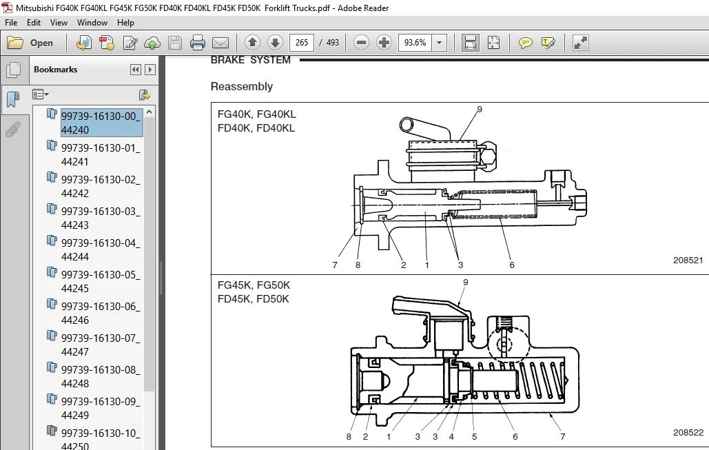
Master Cylinder (FG40K, FG40KL, FD40K, FD40KL) 10 – 3
Master Cylinder (FG45K, FG50K, FD45K, FD50K) 10 – 4
Reservoir Tank 10 – 5
Wheel Brakes (FG40K, FG40KL, FD40K, FD40KL) 10 – 6
Wheel Brakes (FG45K, FG50K, FD45K, FD50K) 10 – 7
Brake Booster (Manual Transmission Type) 10 – 8
Brake Booster (Powershift Transmission Type) 10 – 9
Master Cylinder 10 – 10
Disassembly 10 – 10
Inspection and Repair 10 – 11
Reassembly 10 – 12
Wheel Cylinders 10 – 13
Disassembly 10 – 13
Inspection and Repair 10 – 14
Reassembly 10 – 14
Wheel Brakes 10 – 15
Disassembly 10 – 15
Inspection and Repair 10 – 17
Reassembly (FG40K, FG40KL, FD40K, FD40KL) 10 – 19
Reassembly (FG45K, FG50K, FD45K, FD50K) 10 – 20
Parking Brake Lever 10 – 23
Adjustment and Test 10 – 24
Automatic Adjuster Test 10 – 24
Manual Adjustment 10 – 24
Brake Line Bleeding 10 – 25
Brake Pedal 10 – 26
Brake Booster Test 10 – 27
BRAKE SYSTEM
10
Troubleshooting 10 – 29
Service Data 10 – 31
Structure and Function 11 – 1
Tilt Steering Assembly 11 – 2
Removal and Installation 11 – 3
Removal 11 – 3
Installation 11 – 4
Steering Gear 11 – 6
Disassembly 11 – 6
Inspection and Repair (after disassembly) 11 – 9
Reassembly 11 – 10
Inspection and Repair (after reassembly) 11 – 13
Power Cylinder 11 – 14
Disassembly 11 – 14
Inspection and Repair (after disassembly) 11 – 15
Reassembly 11 – 15
Inspection 11 – 17
Troubleshooting 11 – 18
Service Data 11 – 19
(FHS)
Structure and Functions 11 – 23
General 11 – 23
Steering Hydraulic System 11 – 24
Steering Gear 11 – 25
Tilt Steering Assembly 11 – 26
Removal and Installation 11 – 27
Removal 11 – 27
Installation 11 – 28
STEERING SYSTEM
11
Steering Valve 11 – 29
Disassembly 11 – 29
Inspection 11 – 31
Reassembly 11 – 32
Troubleshooting 11 – 37
Service Data 11 – 38
Structure and Functions 12 – 1
Hydraulic Line (SIS) 12 – 1
Hydraulic Line (FHS) 12 – 2
Hydraulic Tank 12 – 3
Hydraulic Pump 12 – 4
Control Valve 12 – 6
Lift and Tilt Cylinders 12 – 7
Flow Regulator Valve 12 – 11
Down Safety Valve 12 – 12
Removal and Installation 12 – 13
Hydraulic Pump 12 – 13
Control Valve 12 – 14
Lift Cylinders 12 – 16
Tilt Cylinders 12 – 22
Hydraulic Pumps 12 – 23
Disassembly 12 – 23
Inspection and Repair 12 – 24
Reassembly 12 – 25
Control Valve 12 – 26
Disassembly 12 – 26
Inspection and Repair 12 – 27
Reassembly 12 – 27
Lift Cylinders (Simplex Mast) 12 – 28
Disassembly 12 – 28
Inspection and Repair 12 – 30
Lift Cylinders (Duplex Mast, Triplex Mast)12 – 31
Disassembly (No3) 12 – 31
Disassembly (No4) 12 – 32
Disassembly (No5) 12 – 33
Reassembly 12 – 34
HYDRAULIC SYSTEM
12
Lift Cylinders (Triplex Mast)12 – 37
Disassembly (No6) 12 – 37
Disassembly (No7) 12 – 38
Reassembly 12 – 40
Tilt Cylinders 12 – 41
Disassembly 12 – 41
Inspection and Repair 12 – 42
Reassembly 12 – 44
Flow Regulator Valve 12 – 46
Disassembly 12 – 46
Inspection 12 – 46
Reassembly 12 – 46
Down Safety Valve 12 – 48
Disassembly 12 – 48
Inspection 12 – 48
Reassembly 12 – 48
Inspection and Adjustment 12 – 49
Hydraulic Tank 12 – 49
Hydraulic Pump Test Run 12 – 50
Control Valve 12 – 51
Main Relief Valve 12 – 52
Flow Divider Relief Valve 12 – 53
Overload Relief Valve 12 – 54
Flow Regulator Valve 12 – 55
Lift and Tilt Cylinders 12 – 55
Testing 12 – 57
Hydraulic Circuit Diagram (SIS) 12 – 58
Hydraulic Circuit Diagram (FHS) 12 – 59
Piping of Hydraulic System (FHS) 12 – 60
Troubleshooting 12 – 61
Service Data 12 – 65
Specifications 13 – 1
Structure 13 – 2
Simplex Mast (4V40A, 4V45A, 4V50A) 13 – 2
Duplex Mast (4F40A, 4F45A, 4F50A) 13 – 3
Triplex Mast (4M40A, 4M45A, 4M50A) 13 – 4
Removal and Installation 13 – 6
Mast and Lift Bracket Assembly 13 – 6
Disassembly and Reassembly 13 – 12
Simplex Mast 13 – 12
Duplex Mast 13 – 16
Triplex Mast 13 – 21
Inspection and Adjustment 13 – 25
Forks 13 – 25
Chain, Chain Wheel Support and Chain Wheel 13 – 26
Chain Tension Adjustment 13 – 27
Clearance Adjustment on Lift Bracket 13 – 30
Mast Clearance Adjustment 13 – 32
Main Roller Shim Replacement 13 – 34
Mast Strip Adjustment 13 – 38
Tilt Angle Adjustment 13 – 38
Lift Cylinder Stroke Adjustment 13 – 39
Troubleshooting 13 – 40
Service Data 13 – 41
MAST AND FORKS
13
Tightening Torque for Standard Bolts and Nuts 14 – 1
Maintenance Schedule 14 – 3
Parts to be Changed Periodically 14 – 8
Lubrication Instructions 14 – 10
Lubrication Chart 14 – 10
Fuel and Lubricant Specifications 14 – 11
Recommended Brands of Lubricants 14 – 12
Refill Capacities 14 – 13
Weight of Major Components 14 – 13
Special Tools 14 – 14
Radiator Screen Kit 15 – 1
Plate Fin Type Radiator Kit 15 – 2
Elevated Exhaust Kit 15 – 3
Headlamp Kit (mast mounted) 15 – 4
Tail Lamp Upper Relocate Kit 15 – 7
Battery Switch Kit 15 – 8
Extinguisher Kit 15 – 10
Back Mirror Kit 15 – 11
Drawbar Pin 15 – 12
Low Head Guard Kit 15 – 13
Semi Under Side Guard Kit 15 – 14
Torque Converter Oil Filter Kit 15 – 16
Hydraulic Oil Cooler Kit 15 – 18
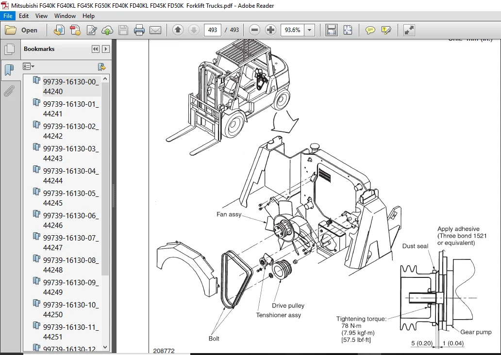
Gear Pump Seal Kit 15 – 22
PLEASE NOTE:
- This is the SAME MANUAL used by the dealerships to diagnose your vehicle
- No waiting for couriers / posts as this is a PDF manual and you can download it within 2 minutes time once you make the payment.
- Your payment is all safe and the delivery of the manual is INSTANT – You will be taken to the DOWNLOAD PAGE.
- So have no hesitations whatsoever and write to us about any queries you may have : heydownloadss @gmail.com
Conrad Callahan –