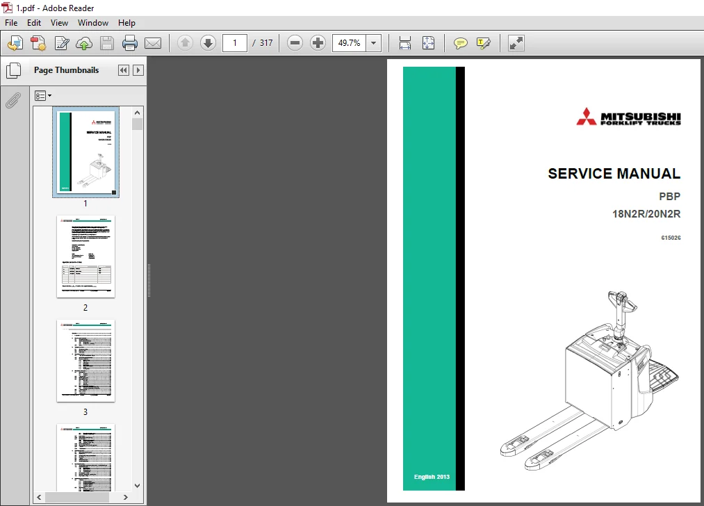
Mitsubishi Forklift PBP 18N2R 20N2R Service Manual – PDF DOWNLOAD
Original price was: $67.95.$32.95Current price is: $32.95.
Mitsubishi Forklift PBP 18N2R 20N2R Service Manual – PDF DOWNLOAD
Description
Mitsubishi Forklift PBP 18N2R 20N2R Service Manual – PDF DOWNLOAD
FILE DETAILS:
Mitsubishi Forklift PBP 18N2R 20N2R Service Manual – PDF DOWNLOAD
Format: PDF
Language: English
Brand: Mitsubishi
MITSUBISHI FORKLIFT PBP 18N2R 20N2R SERVICE MANUAL – PDF DOWNLOAD:
IMAGES PREVIEW OF THE MANUAL:
DESCRIPTION:
Mitsubishi Forklift PBP 18N2R 20N2R Service Manual – PDF DOWNLOAD
FOREWORD:
This service manual is a guide for servicing lift trucks. The long productive life of your lift truck depends on regular and proper servicing, consistent with the instructions provided in this service manual. Before starting to test, repair or rebuild a lift truck, read the respective sections of this manual carefully and familiarize yourself with all of the components. The descriptions, illustrations and specifications contained in this manual are for lift trucks with serial numbers in effect at the time of printing. The manufacturer reserves the right to change specifications or designs without notice and without incurring obligations. For your convenience, the instructions are grouped by systems as an easy reference. Unauthorized copying and lending of this material is strictly prohibited.
Work safety:
- Unauthorized truck modification is not permitted. No modifications or alterations to a powered industrial truck, which could affect, for example, capacity, stability or safety requirements of the truck, shall be made without the prior written approval of the original truck manufacturer, its authorized representative, or a successor thereof.
- This includes changes affecting, for example, braking, steering, visibility and the addition of removable attachments. When the manufacturer or his successor approves a modification or alteration, the manufacturer or successor shall also make and approve appropriate changes to the capacity plate, decals, tags and operation and maintenance handbooks.
- Only in the event that the truck manufacturer is no longer in business and there is no successor in the interest to the business, may the user arrange for a modification or alteration to a powered industrial truck, provided, however, that the user:
a. arranges for the modification or alteration to be designed, tested and implemented by an engineer(s) expert in industrial trucks and their safety,
b. maintains a permanent record of the design, test(s) and implementation of the modification or alteration,
c. approves and makes appropriate changes to the capacity plate(s), decals, tags and instruction handbook, and © Mitsubishi Forklift Trucks 2013. All rights reserved. Revision: A Document ID: 618022 13 (210) PBP Service Manual
d. affixes a permanent and readily visible label to the truck stating the manner in which the truck has been modified or altered, together with the date of the modification or alteration and the name and address of the organization that accomplished those tasks.
• Switch off the truck’s power before opening the cover of the motor compartment or the electrical system.
• Relieve all pressure in the air, oil or water systems before disconnecting or removing any lines, fittings or related items. Release the residual pressure when removing a pressurized device.
• With sit-on trucks, dismount the seat for the duration of the service work.
• Before operating, lubricating or repairing the product, read all warning plates and decals on the truck.
• Do not use your hands to check for oil leaks.
• To avoid burns, pay attention to the hot sections and hot fluids in lines, tubes and compartments, even when the truck is idle or off.
• Only use clean oil in the hydraulic system.
• Repairs requiring welding should be performed only with the appropriate reference information and by personnel adequately trained and knowledgeable in welding procedures. Determine the type of metal and select the correct welding procedure and electrodes, rods or wire to provide a weld metal strength equivalent at least to that of the parent metal.
• When welding, always disconnect the battery and electronic devices. Remove all paint from a 10 cm radius from the welding point to avoid creating toxic gases during welding.
• Use proper lifting procedures when removing any components.
• Be careful when removing cover plates. Gradually remove the last two bolts or nuts located at opposite ends of the cover or device. Before removing the last two bolts or nuts completely, pry the cover loose to relieve any springs or other pressures.
• Be careful when removing filler caps, breathers and plugs on the truck. Wrap a cloth around the cap or plug to prevent being sprayed or splashed by liquids under pressure. Be aware that the danger of being sprayed or splashed is always greater immediately after stopping the truck, as the fluids are very hot.
• Use only well-maintained tools. Also make sure that you use the tools in a proper way.
• Reinstall all fasteners with the same part number. If a replacement is needed, do not use a fastener of lesser quality.
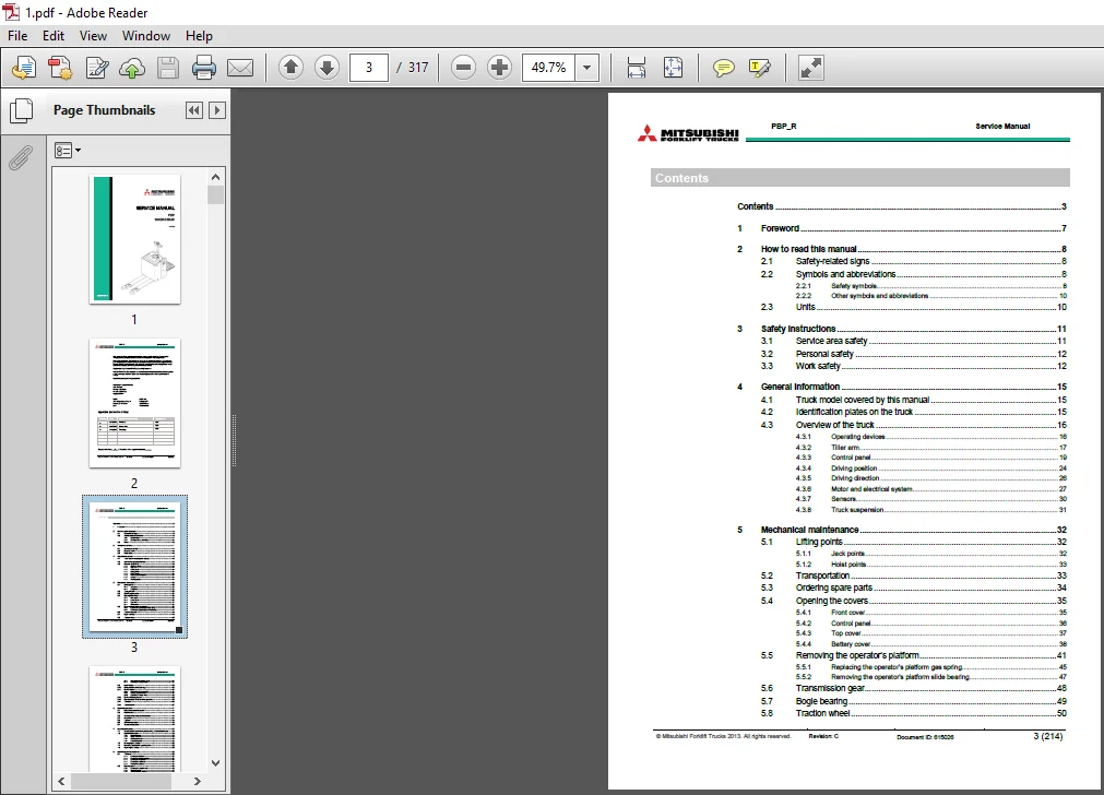
TABLE OF CONTENTS:
Mitsubishi Forklift PBP 18N2R 20N2R Service Manual – PDF DOWNLOAD
Contents 3
1 Foreword 7
2 How to read this manual 8
2 1 Safety-related signs 8
2 2 Symbols and abbreviations 8
2 2 1 Safety symbols 8
2 2 2 Other symbols and abbreviations 10
2 3 Units 10
3 Safety instructions 11
3 1 Service area safety 11
3 2 Personal safety 12
3 3 Work safety 12
4 General information 15
4 1 Truck model covered by this manual 15
4 2 Identification plates on the truck 15
4 3 Overview of the truck 16
4 3 1 Operating devices 16
4 3 2 Tiller arm 17
4 3 3 Control panel 19
4 3 4 Driving position 24
4 3 5 Driving direction 26
4 3 6 Motor and electrical system 27
4 3 7 Sensors 30
4 3 8 Truck suspension 31
5 Mechanical maintenance 32
5 1 Lifting points 32
5 1 1 Jack points 32
5 1 2 Hoist points 33
5 2 Transportation 33
5 3 Ordering spare parts 34
5 4 Opening the covers 35
5 4 1 Front cover 35
5 4 2 Control panel 36
5 4 3 Top cover 37
5 4 4 Battery cover 38
5 5 Removing the operator’s platform 41
5 5 1 Replacing the operator’s platform gas spring 45
5 5 2 Removing the operator’s platform slide bearing 47
5 6 Transmission gear 48
5 7 Bogie bearing 49
5 8 Traction wheel 50
© Mitsubishi Forklift Trucks 2013 All rights reserved Revision: C Document ID: 615026 4 (214)
PBP_R Service Manual
5 8 1 Disassembly of the traction wheel 51
5 8 2 Assembly of the traction wheel 53
5 9 Load wheels 53
5 10 Lifting system and fork carriage 55
5 11 Castor wheels 57
5 11 1 Disassembly of the castor wheel 58
5 11 2 Adjusting the castor wheels 58
5 11 3 Assembly of the castor wheel 59
5 12 Castor wheel suspension 60
5 13 Disassembly of the drive unit suspension 62
5 14 Tiller arm 65
5 15 Tiller arm joint 67
6 Electrical operation 71
6 1 Using the schematic diagram 71
6 2 Power source 74
6 3 Safety circuit (emergency stop button) 74
6 4 Key switch 74
6 5 Traction 75
6 6 AC motor operation 75
6 7 Sensorless operation 76
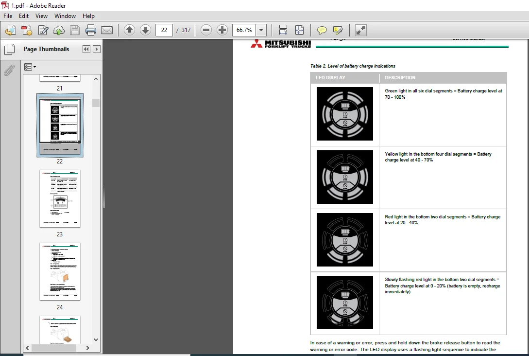
7 Battery maintenance 77
7 1 Safety regulations concerning the handling of lead-acid batteries 78
7 2 Battery maintenance 79
7 2 1 Daily maintenance 79
7 2 2 Weekly maintenance 79
7 2 3 Monthly maintenance 79
7 2 4 Annual maintenance 80
7 3 Recharging the battery 80
7 4 Measuring the battery’s specific gravity 83
7 5 Replacing the battery 83
8 Electric system maintenance 86
8 1 Tiller arm 86
8 1 1 Removing the tiller head 86
8 1 2 Removing the tiller head switches 88
8 1 3 Removing the safety button 89
8 1 4 Removing the accelerator 91
8 1 5 Installing the accelerator 93
8 2 Electric panel 95
8 2 1 Removing the controller cover 96
8 2 2 Traction controller 97
8 2 3 Traction controller connectors 97
8 2 4 Contactors and relays 102
8 2 5 Fuses 103
8 2 6 Removing the electric panel 104
8 3 Truck connector 105
© Mitsubishi Forklift Trucks 2013 All rights reserved Revision: C Document ID: 615026 5 (214)
PBP_R Service Manual
8 3 1 Replacing the truck connector 106
8 4 Motor compartment 107
8 4 1 Removing the drive unit 108
8 4 2 Disassembly of the drive unit 109
8 4 3 Installation of the traction motor 109
8 4 4 Assembly of the splined shaft-hub connection 110
8 4 5 Temperature sensor check 111
8 4 6 Magnetic brake 112
8 5 Pump motor 113
8 5 1 Solenoid valve 114
8 6 Sensors 115
8 6 1 Tiller and operator’s platform sensors 115
8 7 Switches and buttons 117
8 7 1 Emergency stop button 117
8 7 2 Key switch 118
8 7 3 Tiller head microswitch 119
8 8 Horn 120
8 8 1 Diode test with a multimeter 121
8 9 Wiring harnesses and cables 121
8 9 1 Installing the traction motor cables 124
9 Electric system adjustments and measurements 126
9 1 Calibrating the accelerator 126
9 1 1 Acquiring the VACC with TruckTool 126
9 1 2 Acquiring the VACC without Truck Tool 127
9 2 Insulation resistance test 127
9 2 1 Test voltage 127
9 2 2 Checking the insulation tester 128
9 2 3 Measuring the insulation resistance 128
10 Hydraulic operation 131
10 1 Hydraulic symbols 133
10 2 Hydraulic oil recommendations 135
10 3 Maintenance points of the hydraulic system 135
10 4 Hydraulic aggregate 136
10 4 1 Disassembly of the hydraulic aggregate 136
10 4 2 Disassembly of the oil tank 137
10 5 Replacing the hydraulic cylinder 138
10 5 1 Replacing the hydraulic cylinder’s slide bearings 140
11 TruckTool Diagnostics 141
12 Parameter descriptions 142
12 1 Traction controller 142
13 Alarm codes 149
13 1 Traction controller 149
14 Service data 168
© Mitsubishi Forklift Trucks 2013 All rights reserved Revision: C Document ID: 615026 6 (214)
PBP_R Service Manual
14 1 Special tightening torques 168
14 2 Tightening torque for standard bolts and nuts 169
14 3 Maintenance check list 171
14 4 Lubrication 173
14 4 1 Hydraulic oil 173
14 4 2 Transmission oil 173
14 5 Special tools 174
15 Options 175
15 1 Pallet entry / exit rollers 176
15 1 1 Disassembly of the pallet entry / exit rollers 176
15 2 Load support 177
15 2 1 Installation of the load support 178
15 3 Accessory rack 178
15 3 1 Installation of the accessory rack 179
15 4 Lever for lifting and lowering 185
15 4 1 Removing the controller for lifting and lowering 186
15 4 2 Installing the controller for lifting and lowering 187
15 4 3 Calibrating the controller for lifting and lowering 187
15 5 Voltage converter 189
15 5 1 Installation of the voltage converter 190
15 6 Battery lock sensor 191
15 6 1 Installation of the battery lock sensor 192
15 6 2 Battery lock sensor functionality check 193
15 7 Battery connector 193
15 7 1 Replacing the battery connector 194
15 8 Charger connector 194
15 8 1 Replacing the charger connector 195
15 9 Quick battery replacement 195
15 9 1 Removing a discharged battery with the battery changing device 195
15 9 2 Installing a recharged battery with the battery changing device 197
15 9 3 Removing the rubber absorbers 198
15 10 Load stability control 198
15 10 1 Installation of the load stability control 199
15 10 2 Adjusting the gas springs 200
15 10 3 Disassembly of the gas springs 200
16 Technical specification 201
17 Index 205
APPENDIX A: Stickers 209
PLEASE NOTE:
- This is the same manual used by the dealers to diagnose and troubleshoot your vehicle
- You will be directed to the download page as soon as the purchase is completed. The whole payment and downloading process will take anywhere between 2-5 minutes
- Need any other service / repair / parts manual, please feel free to contact [email protected] . We still have 50,000 manuals unlisted