Mitsubishi Forklift SBP 12N 16N 16NI 20N Service Manual – PDF DOWNLOAD
Original price was: $78.95.$33.95Current price is: $33.95.
Mitsubishi Forklift SBP 12N 16N 16NI 20N Service Manual – PDF DOWNLOAD
Pub.No: 619099
Description
Mitsubishi Forklift SBP 12N 16N 16NI 20N Service Manual – PDF DOWNLOAD
FILE DETAILS:
Mitsubishi Forklift SBP 12N 16N 16NI 20N Service Manual – PDF DOWNLOAD
Format: PDF
Language: English
Brand: Mitsubishi
MITSUBISHI FORKLIFT SBP 12N 16N 16NI 20N SERVICE MANUAL – PDF DOWNLOAD:
IMAGES PREVIEW OF THE MANUAL:
DESCRIPTION:
Mitsubishi Forklift SBP 12N 16N 16NI 20N Service Manual – PDF DOWNLOAD
Pub.No: 619099
FOREWORD:
This service manual is a guide for servicing lift trucks. The long productive life of your lift truck depends on regular and proper servicing, consistent with the instructions provided in this service manual. Before starting to test, repair or rebuild a lift truck, read the respective sections of this manual carefully and familiarize yourself with all of the components. The descriptions, illustrations and specifications contained in this manual are for lift trucks with serial numbers in effect at the time of printing. The manufacturer reserves the right to change specifications or designs without notice and without incurring obligations. For your convenience, the instructions are grouped by systems as an easy reference. Unauthorized copying and lending of this material is strictly prohibited.
Work safety:
- Unauthorized truck modification is not permitted. No modifications or alterations to a powered industrial truck, which could affect, for example, capacity, stability or safety requirements of the truck, shall be made without the prior written approval of the original truck manufacturer, its authorized representative, or a successor thereof.
- This includes changes affecting, for example, braking, steering, visibility and the addition of removable attachments. When the manufacturer or his successor approves a modification or alteration, the manufacturer or successor shall also make and approve appropriate changes to the capacity plate, decals, tags and operation and maintenance handbooks.
- Only in the event that the truck manufacturer is no longer in business and there is no successor in the interest to the business, may the user arrange for a modification or alteration to a powered industrial truck, provided, however, that the user:
a. arranges for the modification or alteration to be designed, tested and implemented by an engineer(s) expert in industrial trucks and their safety,
b. maintains a permanent record of the design, test(s) and implementation of the modification or alteration,
c. approves and makes appropriate changes to the capacity plate(s), decals, tags and instruction handbook, and © Mitsubishi Forklift Trucks 2013. All rights reserved. Revision: A Document ID: 618022 13 (210) PBP Service Manual
d. affixes a permanent and readily visible label to the truck stating the manner in which the truck has been modified or altered, together with the date of the modification or alteration and the name and address of the organization that accomplished those tasks.
• Switch off the truck’s power before opening the cover of the motor compartment or the electrical system.
• Relieve all pressure in the air, oil or water systems before disconnecting or removing any lines, fittings or related items. Release the residual pressure when removing a pressurized device.
• With sit-on trucks, dismount the seat for the duration of the service work.
• Before operating, lubricating or repairing the product, read all warning plates and decals on the truck.
• Do not use your hands to check for oil leaks.
• To avoid burns, pay attention to the hot sections and hot fluids in lines, tubes and compartments, even when the truck is idle or off.
• Only use clean oil in the hydraulic system.
• Repairs requiring welding should be performed only with the appropriate reference information and by personnel adequately trained and knowledgeable in welding procedures. Determine the type of metal and select the correct welding procedure and electrodes, rods or wire to provide a weld metal strength equivalent at least to that of the parent metal.
• When welding, always disconnect the battery and electronic devices. Remove all paint from a 10 cm radius from the welding point to avoid creating toxic gases during welding.
• Use proper lifting procedures when removing any components.
• Be careful when removing cover plates. Gradually remove the last two bolts or nuts located at opposite ends of the cover or device. Before removing the last two bolts or nuts completely, pry the cover loose to relieve any springs or other pressures.
• Be careful when removing filler caps, breathers and plugs on the truck. Wrap a cloth around the cap or plug to prevent being sprayed or splashed by liquids under pressure. Be aware that the danger of being sprayed or splashed is always greater immediately after stopping the truck, as the fluids are very hot.
• Use only well-maintained tools. Also make sure that you use the tools in a proper way.
• Reinstall all fasteners with the same part number. If a replacement is needed, do not use a fastener of lesser quality.
TABLE OF CONTENTS:
Mitsubishi Forklift SBP 12N 16N 16NI 20N Service Manual – PDF DOWNLOAD
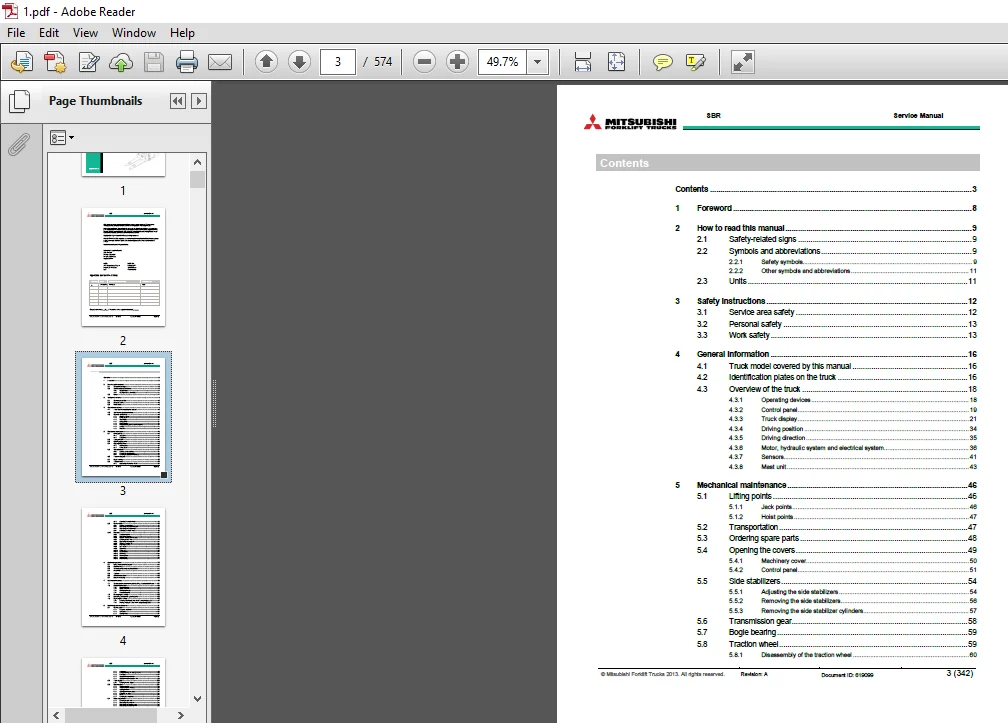
Contents 3
1 Foreword 8
2 How to read this manual 9
2 1 Safety-related signs 9
2 2 Symbols and abbreviations 9
2 2 1 Safety symbols 9
2 2 2 Other symbols and abbreviations 11
2 3 Units 11
3 Safety instructions 12
3 1 Service area safety 12
3 2 Personal safety 13
3 3 Work safety 13
4 General information 16
4 1 Truck model covered by this manual 16
4 2 Identification plates on the truck 16
4 3 Overview of the truck 18
4 3 1 Operating devices 18
4 3 2 Control panel 19
4 3 3 Truck display 21
4 3 4 Driving position 34
4 3 5 Driving direction 35
4 3 6 Motor, hydraulic system and electrical system 36
4 3 7 Sensors 41
4 3 8 Mast unit 43
5 Mechanical maintenance 46
5 1 Lifting points 46
5 1 1 Jack points 46
5 1 2 Hoist points 47
5 2 Transportation 47
5 3 Ordering spare parts 48
5 4 Opening the covers 49
5 4 1 Machinery cover 50
5 4 2 Control panel 51
5 5 Side stabilizers 54
5 5 1 Adjusting the side stabilizers 54
5 5 2 Removing the side stabilizers 56
5 5 3 Removing the side stabilizer cylinders 57
5 6 Transmission gear 58
5 7 Bogie bearing 59
5 8 Traction wheel 59
5 8 1 Disassembly of the traction wheel 60
© Mitsubishi Forklift Trucks 2013 All rights reserved Revision: A Document ID: 619099 4 (342)
SBR Service Manual
5 8 2 Assembly of the traction wheel 62
5 9 Castor wheel 63
5 9 1 Adjusting the castor wheel 64
5 9 2 Disassembly of the castor wheel unit 65
5 9 3 Disassembly of the castor wheel 65
5 9 4 Assembly of the castor wheel 66
5 10 Mast unit 67
5 10 1 Detailed construction 67
5 10 2 Mast unit maintenance 78
5 10 3 Lubricant and fluid recommendations 79
5 10 4 Removing the mast unit 79
5 10 5 Disassembly of the mast unit 104
5 10 6 Triplex mast with free lift 123
5 10 7 Inspecting the forks 133
5 10 8 Load wheels 135
5 10 9 Mast chains 136
5 10 10 Chain yoke 145
5 10 11 Guidance rollers 147
5 10 12 Main rollers 150
5 10 13 Free lift cylinder 153
5 10 14 Side cylinders 159
5 10 15 Initial lift cylinder 171
6 Electrical operation 174
6 1 Using the schematic diagram 174
6 2 Power source 177
6 3 Safety circuit (emergency stop button) 177
6 4 Key switch 177
6 5 Traction 178
6 6 AC motor operation 178
6 7 Electrical steering 179
7 Battery maintenance 180
7 1 Safety regulations concerning the handling of lead-acid batteries 181
7 2 Battery maintenance 182
7 2 1 Daily maintenance 182
7 2 2 Weekly maintenance 182
7 2 3 Monthly maintenance 182
7 2 4 Annual maintenance 183
7 3 Recharging the battery 183
7 4 Measuring the battery’s specific gravity 186
7 5 Replacing the battery 186
7 5 1 Removing a discharged battery with the battery changing device 187
7 5 2 Installing a recharged battery with the battery changing device 189
8 Electric system maintenance 191
8 1 Control panel 191
8 1 1 Emergency stop button 192
8 1 2 Start button 193
8 1 3 Steering wheel 194
© Mitsubishi Forklift Trucks 2013 All rights reserved Revision: A Document ID: 619099 5 (342)
SBR Service Manual
8 1 4 Accelerator 195
8 1 5 Controller for lifting and lowering the forks 196
8 1 6 Horn button 197
8 1 7 Side stabilizers control switch 198
8 1 8 Side stabilizers down-position switch 199
8 2 Truck display 200
8 2 1 Removing the truck display 200
8 3 Electric panel 201
8 3 1 Traction controller 202
8 3 2 Traction controller connectors 202
8 3 3 Steering controller 206
8 3 4 Steering controller connectors 207
8 3 5 Contactors and relays 210
8 3 6 Fuses 211
8 3 7 Removing the controller fan 212
8 4 Motor compartment 213
8 4 1 Removing the drive unit 214
8 4 2 Disassembly of the drive unit 215
8 4 3 Disassembly of the traction motor 216
8 4 4 Disassembly of the steering motor 216
8 4 5 Installation of the traction motor 217
8 4 6 Ball bearings of the traction motor 217
8 4 7 Assembly of the splined shaft-hub connection 218
8 4 8 Temperature sensor check 219
8 4 9 Removing the motor fan 220
8 4 10 Magnetic brake 220
8 5 Pump motor 221
8 5 1 SBR12N pump motor 222
8 5 2 SBR16N(I)/20N pump motor 222
8 5 3 Solenoid valve 223
8 6 Sensors 224
8 6 1 Battery lock sensor 224
8 6 2 Initial lift upper limit sensor 225
8 6 3 Side stabilizer, height reference and safety pedal sensors 226
8 6 4 Steering reference sensor 229
8 6 5 Pressure sensor 230
9 Electric system adjustments and measurements 231
9 1 Adjusting the electrically powered steering 231
9 1 1 Assembly of the reference sensors 231
9 1 2 Steering teaching 232
9 2 Insulation resistance test 232
9 2 1 Test voltage 232
9 2 2 Checking the insulation tester 233
9 2 3 Measuring the insulation resistance 233
10 Hydraulic operation 236
10 1 Hydraulic symbols 238
10 2 Hydraulic oil recommendations 240
10 3 Maintenance points of the hydraulic system 240
© Mitsubishi Forklift Trucks 2013 All rights reserved Revision: A Document ID: 619099 6 (342)
SBR Service Manual
10 4 Hydraulic aggregate 241
10 4 1 Disassembly of the hydraulic aggregate 242
10 4 2 Solenoid valve M7 243
10 5 Hydraulic valve unit 244
10 5 1 Valves M1, M3, M4, M5 and M6 245
10 5 2 Valve M2 245
10 5 3 Emergency lowering valve 245
10 5 4 Setting the lifting pressure 246
10 5 5 Disassembly of the valves 247
10 5 6 Changing the filter 248
11 Zapi digital console 249
11 1 Connecting the Zapi digital console to the truck 249
11 2 Selecting the controller 250
11 3 Adjusting the parameters with the Zapi digital console 251
12 Parameter descriptions 252
12 1 Traction controller 252
12 2 Pump controller 261
12 3 Steering controller 266
13 Alarm codes 268
13 1 Traction controller 268
13 2 Pump controller 278
13 3 Steering controller 284
14 Service data 291
14 1 Special tightening torques 291
14 2 Tightening torque for standard bolts and nuts 292
14 3 Maintenance check list 294
14 4 Lubrication 297
14 4 1 Hydraulic oil 297
14 4 2 Transmission oil 297
14 5 Special tools 297
15 Options 299
15 1 Special color for side plates 300
15 2 Equipment for freezing conditions 301
15 3 Lowered overhead guard 303
15 4 Load support 303
15 4 1 Installation of the load support 304
15 5 Rear view mirror 304
15 5 1 Installation of the rear view mirror 305
15 6 Adjustable working light 305
15 6 1 Installation of the adjustable working light 306
15 7 Warning light 307
15 7 1 Installation of the warning light 307
15 8 Warning buzzer for driving, lifting and lowering 308
© Mitsubishi Forklift Trucks 2013 All rights reserved Revision: A Document ID: 619099 7 (342)
SBR Service Manual
15 8 1 Installation of the warning buzzer 309
15 9 Powder extinguisher 310
15 9 1 Installation of the powder extinguisher 310
15 10 Joystick 311
15 11 Key switch 313
15 11 1 Installation of the key switch 314
15 11 2 Key switch functionality check 314
15 12 Charger connector 315
15 12 1 Replacing the charger connector 315
15 13 Voltage converter 316
15 13 1 Installation of the voltage converter 316
15 14 Hydraulic side stabilizers for duplex mast units 318
15 15 Reversed steering 319
15 15 1 Activating reversed steering 319
15 16 Driving speed reduction 319
15 16 1 Activating driving speed reduction 319
15 16 2 Driving speed reduction, lift cut-out and side stabilizers sensor 320
15 17 Compulsory lowering of side stabilizers 321
15 17 1 Activating the compulsory lowering of the side stabilizers 321
15 18 Automatic lift cut-out at required lifting height 323
15 18 1 Activating automatic lift cut-out at required lifting height 323
16 Technical specification 325
17 Index 331
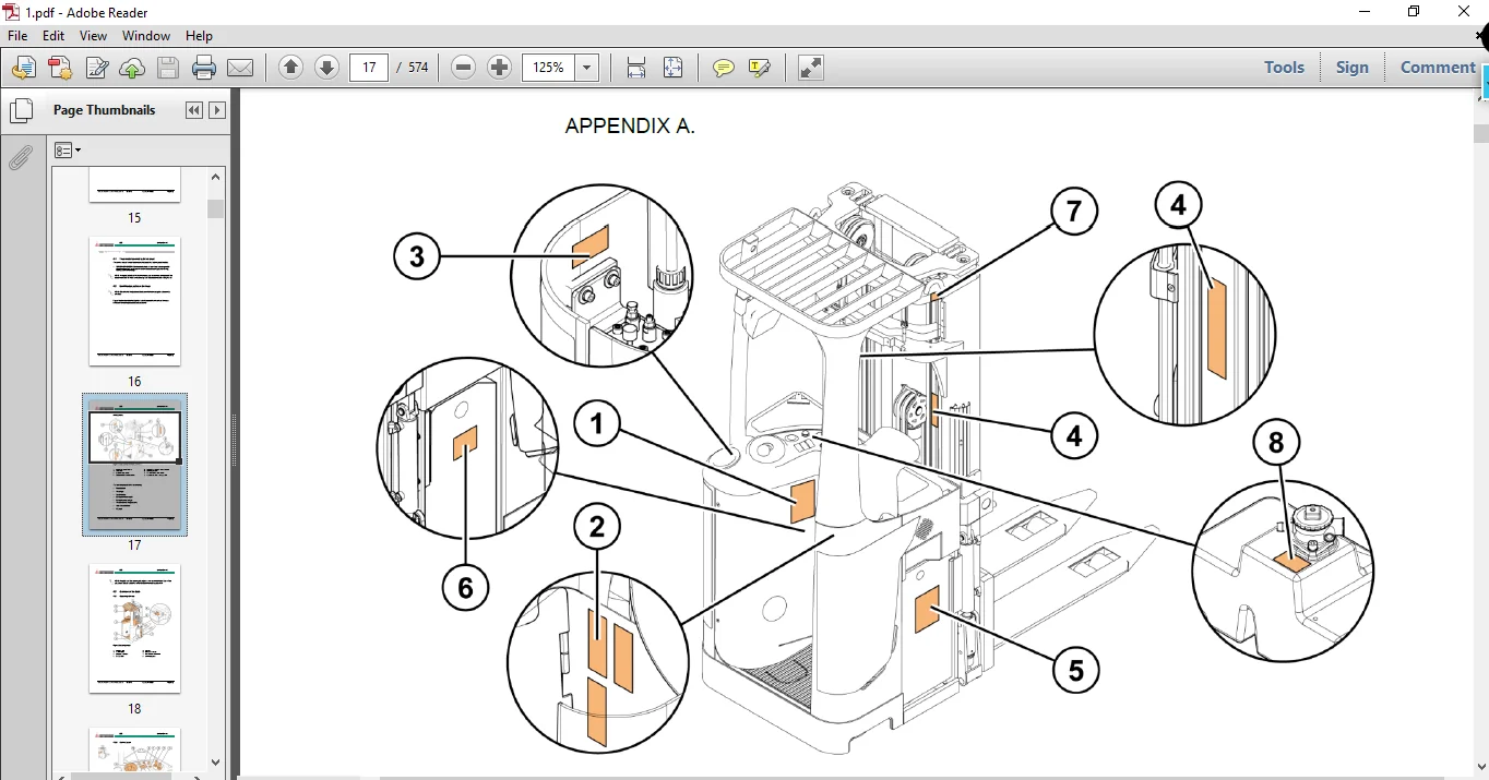
APPENDIX A: Stickers 336
PLEASE NOTE:
- This is the same manual used by the DEALERSHIPS to SERVICE your vehicle.
- The manual can be all yours – Once payment is complete, you will be taken to the download page from where you can download the manual. All in 2-5 minutes time!!
- Need any other service / repair / parts manual, please feel free to contact us at heydownloadss @gmail.com . We may surprise you with a nice offer