
Mitsubishi Fuso 6M6 Euro V Diesel Engine Shop Manual – 6M60T1 & 6M60T2 Repair PDF
Original price was: $59.95.$39.95Current price is: $39.95.
Complete Mitsubishi Fuso 6M6 (Euro V) diesel engine shop manual for the 6M60T1 and 6M60T2 – engine mechanical, common rail, VG turbocharger, cooling, lubrication and BlueTec exhaust aftertreatment, with service standards, special tools and step-by-step procedures.
Description
When a 6M60 comes into the bay with a low-power complaint, a cold-start misfire or a BlueTec warning on the cluster, guessing is expensive. This Mitsubishi Fuso 6M6 Euro V diesel engine shop manual gives you the measured values, the tightening sequences and the disassembly order the engine was built around. Issued under publication number 00E/MT/0007 and dated February 2011, it covers the 6M60T1 and 6M60T2 six-cylinder in-line, water-cooled, direct-injection diesel engines as fitted to the Euro V Fuso truck range, and it is written for the technician working on the unit rather than for the showroom.
File Details
- Manual type: Diesel engine shop manual (service, repair, adjustment and diagnostics)
- Brand: Mitsubishi Fuso
- Engine series: 6M6 (Euro V)
- Applicable engine models: 6M60T1, 6M60T2
- Publication number: 00E/MT/0007
- Edition / date: February 2011
- Language: English
- Page count: 533 pages
- File format: PDF
Chapters Covered
The manual follows Mitsubishi Fuso’s own group numbering, and the engine volume runs through these groups:
- General (Group 00)
- Engine (Group 11)
- Lubrication (Group 12)
- Fuel and Engine Control (Group 13)
- Common Rail System (Group 13E)
- Cooling (Group 14)
- Intake and Exhaust (Group 15)
- Variable Geometry Turbocharger (Group 15E)
- Emission Control (Group 17)
- BlueTec Exhaust Gas Aftertreatment (Group 17E)
General – Equipment Identification and Workshop Practice
Group 00 opens with the equipment type coding system and the power train table, so you can decode a chassis number and work out exactly which engine, clutch, transmission, axle and reduction unit a vehicle left the line with. It then sets out how to read the manual itself: what a standard value means versus a limit, how tightening torques are presented in SI units with metric equivalents in braces, and what the T, P, X, A and C symbols in the illustrated parts breakdowns actually tell you. The safety material is practical rather than decorative – cab tilt and stay locking, lifting the engine with the correct hangers, battery isolation before electrical work, probe and connector handling, and the arc welding procedure that keeps control units alive. Jacking and rigid-rack support points are given separately for front and rear, including the air suspension and frame lift variations.
Engine Mechanical – Group 11
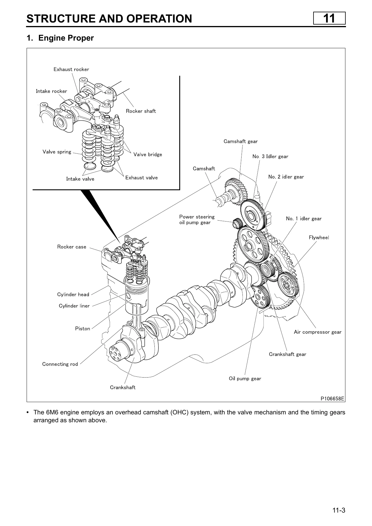
This is the heart of the book. It begins with structure and operation drawings of the engine proper, the overhead camshaft arrangement, the rocker and bracket assembly, the valve mechanism, connecting rod, piston, timing gear train, flywheel and flywheel PTO, then moves into the work itself. You get compression pressure measurement with the injectors removed and the correct adapter, valve clearance inspection and adjustment cold at 0.6 mm with the No. 1 or No. 6 piston at TDC on compression, engine removal and installation with the front and rear hangers, and then the long-form procedures: rocker cover, rocker and bracket and camshaft; cylinder head and valve mechanism including valve guide and seat replacement, lapping and cylinder head gasket class selection by piston projection; piston, connecting rod and cylinder liner with the size-mark matching system; flywheel PTO; flywheel for both manual and automatic transmission applications; timing gears with and without flywheel PTO; and finally crankshaft and crankcase with undersize grinding dimensions, main bearing cap tightening by torque-turn and thrust plate installation. Every section carries a service standards table with standard value, limit and remedy, plus the special tool part numbers you need to do the job properly.
Lubrication and Cooling – Groups 12 and 14
The lubrication group traces oil from the strainer through the gear-type pump, relief valve, full-flow and bypass filter elements, oil cooler and thermo valve into the main gallery, then breaks out the feeds to the main bearings, connecting rod bearings and bushings, timing gear shafts, camshaft and rocker shaft, the piston cooling oil jets with their check valves, the turbocharger bearing housing and the air compressor. On-vehicle work covers oil filter and engine oil replacement with capacities, oil pressure measurement at the pressure switch port, and the oil pan, oil jet and level sensor procedures. The cooling group covers the forced circulation system and coolant flow, the bottom bypass wax-pellet thermostat, the water pump with its drain hole and bearing unit replacement, belt tension inspection and adjustment with the belt tension gauge, coolant replacement and system cleaning, air bleeding and the gas leakage test.
Fuel System and Common Rail – Groups 13 and 13E
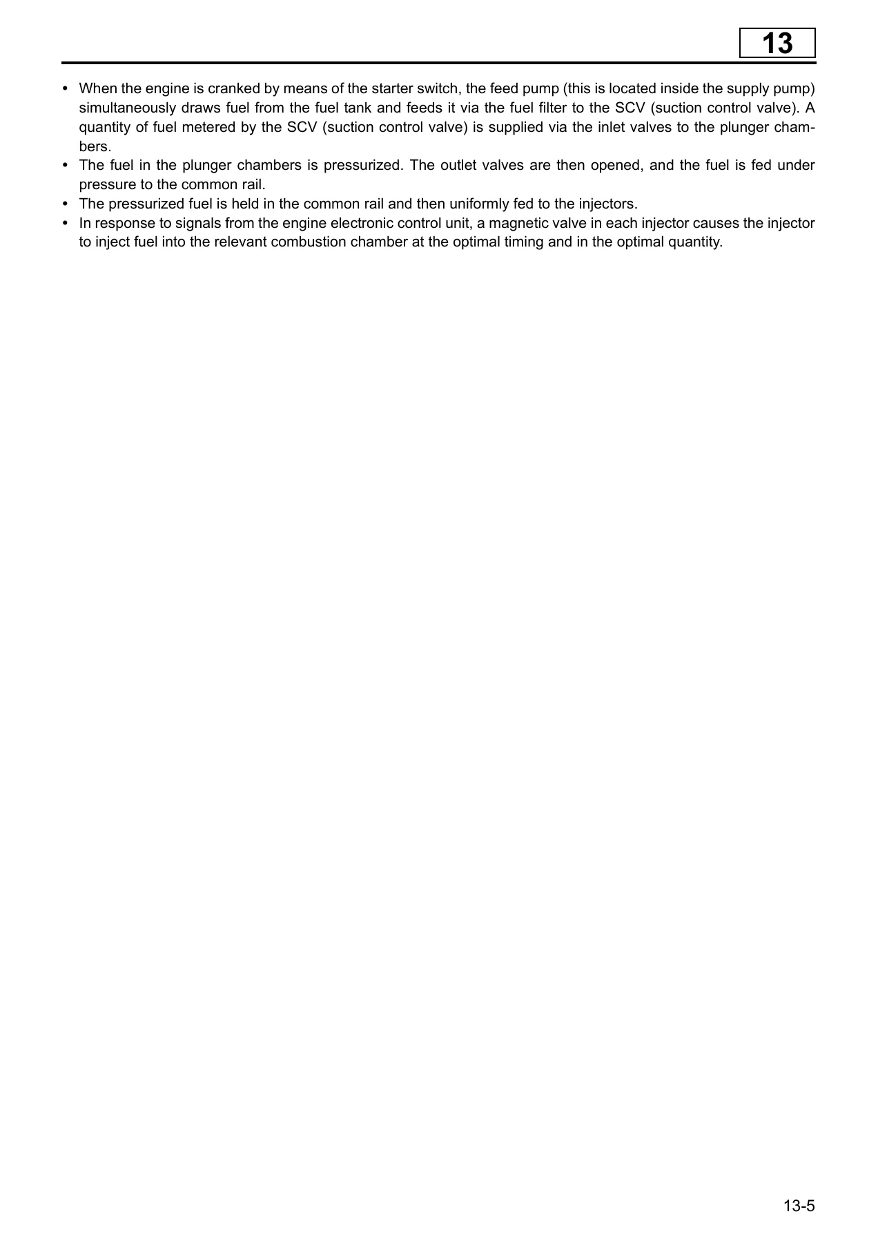
The fuel group explains the DENSO HP-4 electronically controlled supply pump, the suction control valve, the common rail with its flow dampers, pressure limiter and rail pressure sensor, and the solenoid injectors, then gives you the on-vehicle checks: no-load minimum and maximum speed, fuel leakage inspection, injection pipe and fuel pipe clamp inspection, fuel tank draining and fuel system air bleeding. Group 13E is the full electronic control volume – system block diagram, injection quantity, timing and pressure control strategy, warm-up acceleration, auxiliary brake and idle-up functions, the E-OBD group code structure and driving cycle logic, the complete diagnostic trouble code list with generation conditions, recoverability, control effected by the ECU and presumption factors for each code, Multi-Use Tester service data, actuator tests, ECU coding and the connector-by-connector hardware inspection values. Component sections cover the common rail, supply pump, injectors, both fuel tank types, fuel filter and fuel cooler.
Air Management – Groups 15 and 15E
Intake and exhaust covers the air cleaner and ducting, the TD06 variable geometry turbocharger with its water-cooled centre housing, the intercooler, intake manifold and exhaust manifold, exhaust pipe and exhaust shutter. The on-vehicle section is unusually detailed: checking the turbocharger rotor for free play and interference, measuring and correcting boost pressure against ambient temperature and barometric pressure, and adjusting the air cylinder shaft length in known increments per turn. Group 15E explains how the three turbocharger magnetic valves sequence the air cylinder through eight vane positions from full open to full close, and how the turbine speed sensor protects against overspeed.
Emissions – Groups 17 and 17E
The emission control group documents the urea SCR system end to end: the SCR muffler with its catalysts and dosing nozzle, the urea tank with level and temperature sensing plus coolant-heated thawing, the urea supply unit with its diaphragm pump, main filter and accumulator, the urea dosing unit with dosing valve, pressure and temperature sensors and heaters, the air pressure limiting unit, and the full post-run air purge sequence that clears AdBlue from the lines after shutdown. Practical content includes urea filter replacement and cleaning, AdBlue replacement, leak inspection, line damage inspection and accumulator air filling to 370 kPa. Alongside it sits the blowby gas return system and PCV valve element service. Group 17E carries the aftertreatment control module diagnostics – the complete DTC list with generation conditions, FUSO Diagnostics service data, actuator tests, coding, and the wiring-level input and output table with terminal numbers and expected voltages or resistances.
What Makes This Manual Useful in the Bay
The value here is not the page count, it is the fact that every procedure is anchored to a number you can check against. Compression pressure has a standard of 2,940 kPa {30 kgf/cm2} and a limit of 1,960 kPa {20 kgf/cm2}, with a cylinder-to-cylinder spread limit of 390 kPa {4 kgf/cm2}. Cylinder head bolts are tightened to 78 N.m {8 kgf.m} plus three 90 degree steps, wet, reusable up to three times, with punch marks on the head telling you how many times a bolt has already been through the plastic region. Camshaft end play, cam lift, valve guide clearance, piston ring end gap and side clearance, connecting rod bend and twist, crankshaft bend and journal oil clearance – all of it is tabulated with a limit and a stated remedy, so you can condemn a part with confidence instead of replacing it on suspicion.
The same discipline applies to the electronic side. Each diagnostic trouble code in the 13E and 17E listings is broken down into the generation condition, the recoverability condition, what the control unit does while the fault is active, and the presumption factors to work through. That structure turns a code from a starting point into a test plan. The connector hardware tables go further and give terminal pairs with expected resistance or voltage – water temperature sensor, accelerator pedal position sensors, fuel temperature sensors, engine speed sensor, cylinder recognition sensor, injector solenoid resistances, suction control valve resistance, VG turbo solenoid valves, SCR temperature sensors, urea pressure and air pressure sensors, NOx sensor – so you can verify a circuit at the pins rather than at the component in isolation.
Two details make the mechanical side safer to work on. The cylinder head gasket is supplied in three thickness classes, A, B and C, selected by averaging piston projection measurements from twelve points around the crankcase, with a rule for stepping up a class when one measurement runs more than 0.05 mm above the average. And the cylinder liner, piston and crankcase bore all carry size marks that must match – 1, 2, 3 on the crankcase, 1A, 1B, 2A, 2B, 3A, 3B on the liner, A and B on the piston. Get that matching wrong and the result is a seizure, so the manual spells it out with a cross-reference diagram.
Who This Mitsubishi Fuso 6M6 Euro V Diesel Engine Shop Manual Is For
Fleet workshops running Euro V Fuso trucks will use Groups 11 through 17E as their everyday reference for valve clearance checks, injector replacement, turbocharger diagnosis and SCR fault finding. Independent diesel shops taking on a 6M60 rebuild will lean on the piston, liner, crankshaft and timing gear chapters, where the undersize dimensions and interference figures are given outright. Technical colleges and apprentices get a genuinely complete example of how a manufacturer documents an electronically controlled common rail engine with aftertreatment, from the general information chapter through to the wiring tables. Anyone maintaining a 6M60T1 or 6M60T2 will find the maintenance and adjustment values they need without wading through chassis material they do not want, because this is the engine volume and nothing else.
IMAGES PREVIEW
Instant PDF Delivery
The manual is delivered as a PDF file the moment payment clears – no shipping, no waiting for a courier, no damaged spine on a workshop shelf. Open it on a laptop on the bench, a tablet next to the engine, or a phone under the vehicle, and print the pages you need for the job in front of you. If you are doing a cylinder head, print the head chapter and the gasket class table and take them to the machine shop. If you are chasing an intermittent fault, print the DTC list and the connector table and work through them in order. Buying this 6M60T1 and 6M60T2 repair manual once gives you the torque figures, the clearances, the tightening sequences and the diagnostic logic for the whole engine, in a format you can search visually, annotate and keep on file for the next 6M60 that comes through the door.
Reviews
There are no reviews yet.