
Mitsubishi Fuso FK FM FN Euro V Electrical Shop Manual 2011 – 00EMT0009 PDF Download
Original price was: $39.95.$23.95Current price is: $23.95.
Complete Mitsubishi Fuso FK, FM and FN Euro V Electrical Shop Manual (Pub. No. 00EMT0009, February 2011). Covers Group 54 electrical systems, wiring diagrams, starter and alternator service, meter cluster, MVCU, diagnosis codes, troubleshooting and on-vehicle inspection for FK61/FK62/FK65, FM62-FM67 and FN62-FN64 trucks with 6M60T1 and 6M60T2 engines.
Description
Mitsubishi Fuso FK FM FN Euro V Electrical Shop Manual (00EMT0009)
This is the Mitsubishi Fuso FK.FM.FN (EURO V) Electrical Shop Manual, published under document number 00EMT0009 in February 2011. It is the dedicated Group 54 Electrical volume for the FK, FM and FN series trucks built to Euro V emission specification, and it covers every electrical system on the vehicle — from the battery and charging circuit through the meter cluster, lighting, body electrics, chassis electrics, engine and transmission circuits, MVCU, starter and alternator. Rather than a generic wiring booklet, this is the full workshop-grade electrical service manual used to diagnose, test, repair and adjust the complete electrical installation.
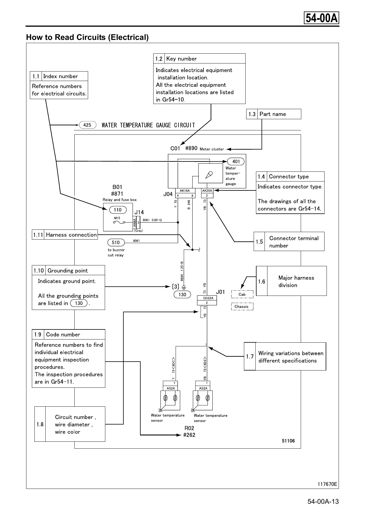
The manual is written for technicians working on FK61, FK62, FK65, FM62, FM63, FM64, FM65, FM67, FN62, FN63 and FN64 models powered by the 6M60T1 (177 kW / 240 PS) and 6M60T2 (199 kW / 270 PS) diesel engines. Every circuit is presented as a fully labelled schematic with connector terminal numbers, wire diameters, wire colours, grounding points, harness divisions and code numbers that tie back to the on-vehicle inspection procedures in Group 54-11. Diagnosis codes, service data and actuator tests for the electrically controlled systems are included so faults can be traced end-to-end.
File Details
- Manual type: Electrical Shop Manual (Group 54)
- Brand: Mitsubishi Fuso
- Series: FK, FM, FN (Euro V)
- Document number: Pub.No.00EMT0009
- Publication date: February 2011
- Language: English
- Page count: 453 pages
- File format: PDF
Chapters Covered
The manual is organised in the same 54-series structure Mitsubishi Fuso uses for its electrical volumes, and the contents below reflect the actual section headings:
- 54-00A General — vehicle model coding system, equipment type coding system, power train table, how to read this manual, chassis number, engine number and name plate, precautions for maintenance operation, jacking up the vehicle, diagnosis codes, reading and erasing diagnosis codes, table of standard tightening torques.
- 54-00B Specifications — battery, alternator, starter, starter relay, glow plug, glow relay, lighting and meter cluster specifications.
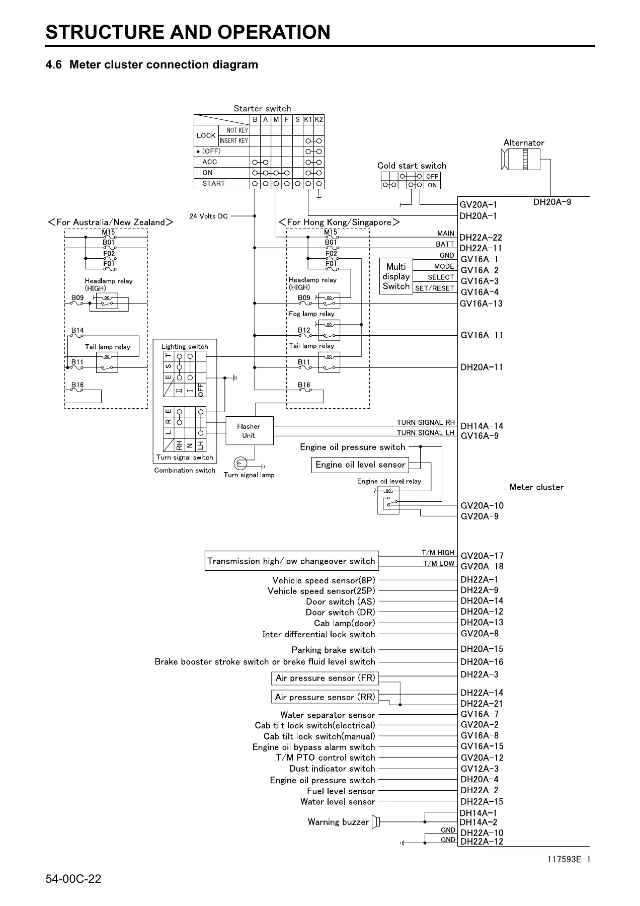
- 54-00C Structure and Operation — starter, alternator (including neutral diode operation), lighting (headlamp, fog lamp), meter cluster (instrument drive, LAC function, indicator and warning lamp function, open-circuit check function, system diagnosis function, meter cluster connection diagram), wiper electronic control unit, engine electronic control unit (starter continuous energizing preventing function and preheating function), MVCU (Multifunction Vehicle Control Unit) with cruise control, vehicle speed limiting and hill start assist.
- 54-00D Troubleshooting — symptom-based fault tables for power and charging, engine starting/stopping/preheating, lighting, meter, cigarette lighter and audio, horn, preheating system, starter continuous energizing preventing function and MVCU.
- 54-01 Power, Charge and Ground Circuit — high-current fuse box, fuse box, relay and fuse box circuit, power circuit, reserve power circuit, battery charging circuit, ground.
- 54-02 Engine Starting, Stopping and Preheating Circuit — engine starting circuit, engine stopping circuit, engine preheating and cold start circuit.
- 54-03 Lighting Circuit — headlamp, fog lamp, tail/position/license plate lamps, stop lamp, turn signal and hazard lamp, backup lamp, cab lamp, illumination lamp, end-outline marker lamp circuits.
- 54-04 Meter Circuit — meter cluster internal circuit, tachometer, speedometer, fuel gauge, water temperature gauge, air gauge and hour meter circuits.
- 54-05 Indicator and Warning Lamp Circuit — parking brake indicator, brake warning, air cleaner element warning, water level warning, engine oil level warning, engine oil pressure warning, engine oil filter warning, transmission high/low indicator, cab tilt warning, starter key removal reminder alarm and fuel filter circuits.
- 54-06 Cab Side Electrical Circuit — cigarette lighter, audio, wiper and washer, horn, air-conditioner, power window and central door lock, power mirror, mirror heater, power tilt and keyless entry circuits.
- 54-07 Chassis Side Electrical Circuit — exhaust brake, differential lock and air suspension circuits.
- 54-08 Engine and Transmission Side Electrical Circuit — transmission power take-off circuit.
- 54-09 Other Circuit — joint connector, MVCU circuit, cruise control and vehicle speed limiting circuit, plus cross-references to the common rail, BlueTec exhaust gas aftertreatment, automatic transmission, electronically controlled brake and SRS airbag circuit diagrams.
- 54-10 Electrical Equipment Installation Positions — cab side (switch/sensor, relay/ECU/fuse, meter/buzzer/motor, air-conditioner, door, roof, cab, power tilt, joints of main harness connectors), engine and transmission (engine, transmission), chassis side (switch/sensor, relay/ECU/fuse, magnetic valve/buzzer/motor, joints of harness connectors).
- 54-11 Inspection of Electrical Equipment — code-numbered inspection procedures (#001 to #999) covering switches, relays, sensors, control units, motors, actuators, magnetic valves, buzzers, horns, lamps, alternator, regulator, preheating system and starter continuous energizing preventing function.
- 54-12 Starter and Alternator — removal, disassembly, inspection, assembly and performance testing of the starter and alternator, including service standards, tightening torques, lubricant and sealant charts and special tools.
- 54-13 On-Vehicle Inspection and Adjustment — alternator, regulator, preheating system, starter continuous energizing preventing function, headlamp aiming, fog lamp aiming and MVCU (Multifunction Vehicle Control Unit) inspection including diagnosis code list, service data and actuator tests.
- 54-14 Connector Configuration Chart — complete connector layout reference covering AA through HU type connectors.
Altogether the manual delivers a complete picture of the FK/FM/FN Euro V electrical architecture: how the harness is routed, how each circuit is protected, where each ground lands, which connector pin carries which signal, and how each electrically controlled function is expected to behave. It is both a repair reference and a diagnostic guide.
Vehicle Coverage
The power train table in Section 54-00A lists the following model and component combinations covered by this manual:
- FK61 — 6M60T1 engine, C7M38 clutch, M060S6 or M070S6 transmission, F400T front axle, R050T rear axle, D050H or D052H reduction and differential.
- FK62 — 6M60T1 engine, C7M38 clutch, M060S6 or M070S6 transmission, F500T front axle, R052T rear axle, D052H reduction and differential.
- FK65 — 6M60T2 engine, C7M38 clutch, M070S6 transmission, F500T front axle, R050T rear axle, D052H reduction and differential.
- FM62 — 6M60T2 engine, C7M38 clutch or torque converter, M060S9 (EATON ES-11109) or M100S6 (ALLISON 3500) transmission, F650T front axle, R10TT/R10T rear axle, D10HT/D10H reduction and differential.
- FM63, FM64 — 6M60T2 engine, M060S9 (EATON ES-11109) or M100S6 (ALLISON 3500) transmission, F650T front axle, R10TT rear axle, D10H reduction and differential.
- FM65, FM67 — 6M60T2 engine, C7M38 clutch, M070S6 or M070S6D or M060S9 (EATON ES-11109) transmission, F650T front axle, R060T or R080T rear axle, D8H or D10H reduction and differential.
- FN62, FN63, FN64 — 6M60T2 engine, M060S9 (EATON ES-11109) or M100S6 (ALLISON 3500) transmission, F650T front axle, R10TT rear axle, D10HT/D10H reduction and differential.
Wheelbases, suspension types (leaf, trunnion, air), brake configurations (air over hydraulic, full air), steering positions and export specifications are all accounted for in the coding system, so the reader can match the manual to the exact truck on the workshop floor.
Engines Covered
- 6M60T1 — 177 kW (240 PS), six-cylinder turbocharged diesel.
- 6M60T2 — 199 kW (270 PS), six-cylinder turbocharged diesel.
What a Technician Can Do With This Electrical Shop Manual
This Mitsubishi Fuso FK FM FN Euro V Electrical Shop Manual is aimed squarely at the working technician. With it in hand you can:
- Read out and erase diagnosis codes through the FUSO Diagnostics tool, the Multi-Use Tester, the multi-information display or warning lamp flashing, depending on the system.
- Trace any electrical fault using the fully annotated circuit diagrams — connector terminal numbers, wire diameter, wire colour, grounding points, harness division and code numbers are all marked so you can find the right pin on the right connector without guesswork.
- Follow the code-numbered inspection procedures in Group 54-11 to test switches, relays, sensors, motors, actuators, magnetic valves, buzzers, horns and lamps against published standard values and limits.
- Diagnose and repair the starter, alternator, regulator and preheating system, including bench testing, pinion gap adjustment and performance verification.
- Adjust headlamp and fog lamp aiming to the specified cut-off line positions using the screw turning directions in the tables.
- Carry out the initialisation and learning procedures required after replacing the meter cluster, and interpret the vehicle control warning lamp and MVCU diagnosis codes.
- Interpret service data and run actuator tests through the Multi-Use Tester to confirm cruise control, vehicle speed limiting and hill start assist operation.
- Use the connector configuration chart in Group 54-14 to identify any of the AA through HU type connectors on the vehicle.
Why the Correct Electrical Procedures and Specifications Matter
Modern Euro V trucks like the FK, FM and FN rely on a dense network of electronic control units — engine ECU, aftertreatment control module, anti-lock brake ECU, automatic transmission ECU, airbag ECU, MVCU — all talking over CAN. The electrical system is not just wiring; it is the nervous system of the vehicle. A misdiagnosed circuit, a probe poked into the wrong terminal, an incorrect torque on a ground bolt, or a battery cable disconnected while the engine is running can all cause expensive damage to diodes, regulators or control units. This manual gives you the correct precautions, the correct test points, the correct values and the correct procedures so that faults are found and fixed without collateral damage.
For any workshop running FK, FM or FN trucks, having the electrical shop manual for the exact model year and specification is the difference between a fast, accurate repair and a long, expensive guessing game.
IMAGES PREVIEW
Instant PDF Delivery
The Mitsubishi Fuso FK FM FN Euro V Electrical Shop Manual (Pub. No. 00EMT0009, February 2011) is delivered as an instant PDF download after purchase. There is no shipping, no waiting for a physical book, and no risk of a lost parcel. Once payment is complete you can open the file on any device — laptop, tablet or smartphone — search, zoom into the detailed circuit diagrams, and print the pages you need for the workshop floor. Keep it on the shop computer, load it on a tablet next to the truck, or print a copy for the bench — it is yours to use however suits the job.
Reviews
There are no reviews yet.