Mitsubishi Outlander 2013 6B3 Workshop Manual – PDF DOWNLOAD
$28.95
Mitsubishi Outlander 2013 6B3 Workshop Manual – PDF DOWNLOAD
Description
Mitsubishi Outlander 2013 6B3 Workshop Manual – PDF DOWNLOAD
FILE DETAILS:
Mitsubishi Outlander 2013 6B3 Workshop Manual – PDF DOWNLOAD
Language : English
Pages : 636
Downloadable : Yes
File Type : PDF
IMAGES PREVIEW OF THE MANUAL:
TABLE OF CONTENTS:
Mitsubishi Outlander 2013 6B3 Workshop Manual – PDF DOWNLOAD
GENERAL 1
GENERAL 3
VEHICLE IDENTIFICATION 4
MODELS 4
VEHICLE IDENTIFICATION NUMBER (CHASSIS NUMBER) 4
VEHICLE IDENTIFICATION 5
MANUFACTURER LABEL 5
ENGINE MODEL STAMPING 6
GENERAL DATA AND SPECIFICATIONS 6
PRECAUTIONS BEFORE SERVICE 7
CODING LIST 7
VARIANT CODING 7
ENGINE ECU CODING DATA LIST 8
ETACS-ECU CODING DATA LIST 8
INITIALISATION PROCEDURE FOR LEARNING VALUE IN MPI ENGINE 9
INITIALISATION PROCEDURE 9
LEARNING PROCEDURE FOR IDLING IN MPI ENGINE 9
PURPOSE 9
LEARNING PROCEDURE 9
INITIALISATION PROCEDURE FOR THROTTLE VALVE CONTROL SERVO 9
GENERAL <ELECTRICAL> 11
OUTLINE OF CHANGE 12
COMPONENT LOCATIONS 12
CONFIGURATION DIAGRAMS 12
CIRCUIT DIAGRAM 12
ENGINE 17
ENGINE MECHANICAL <6B3> 19
SERVICE SPECIFICATIONS 20
SEALANTS 20
SPECIAL TOOLS 21
ON-VEHICLE SERVICE 26
ALTERNATOR & OTHERS BELT TENSION CHECK AND ADJUSTMENT 26
ALTERNATOR DRIVE BELT AUTO-TENSIONER CHECK 26
OPERATION CHECK 26
IGNITION TIMING CHECK 26
IDLE SPEED CHECK 27
IDLE MIXTURE CHECK 28
VALVE CLEARANCE CHECK AND ADJUSTMENT <Intake valve> 29
COMPRESSION PRESSURE CHECK 30
MANIFOLD VACUUM CHECK 31
ROCKER ARM PISTON OPERATION CHECK 31
LASH ADJUSTER CHECK <Exhaust valve> 33
<LASH ADJUSTER AIR BLEEDING> 34
CRANKSHAFT PULLEY 35
REMOVAL AND INSTALLATION 35
REMOVAL SERVICE POINTS 36
INSTALLATION SERVICE POINTS 36
CAMSHAFT OIL SEAL 38
REMOVAL AND INSTALLATION 38
REMOVAL SERVICE POINTS 38
INSTALLATION SERVICE POINTS 39
CAMSHAFT AND VALVE STEM SEAL 40
REMOVAL AND INSTALLATION 40
<LEFT BANK> 40
<RIGHT BANK> 42
REMOVAL SERVICE POINTS 43
INSTALLATION SERVICE POINTS 44
OIL PAN AND OIL STRAINER 48
REMOVAL AND INSTALLATION 48
REMOVAL SERVICE POINTS 49
INSTALLATION SERVICE POINTS 49
INSPECTION 50
CRANKSHAFT FRONT OIL SEAL 51
REMOVAL AND INSTALLATION 51
INSTALLATION SERVICE POINTS 51
CRANKSHAFT REAR OIL SEAL 52
REMOVAL AND INSTALLATION 52
REMOVAL SERVICE POINT 53
INSTALLATION SERVICE POINTS 53
CYLINDER HEAD GASKET 54
REMOVAL AND INSTALLATION 54
REMOVAL SERVICE POINTS 56
INSTALLATION SERVICE POINTS 56
TIMING BELT 58
REMOVAL AND INSTALLATION 58
REMOVAL SERVICE POINTS 59
INSTALLATION SERVICE POINT 60
INSPECTION 61
TIMING BELT AUTO-TENSIONER CHECK 61
AIR BLEEDING METHOD 61
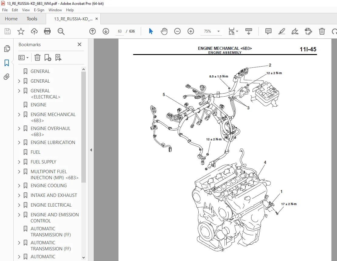
ENGINE ASSEMBLY 62
REMOVAL AND INSTALLATION 62
REMOVAL SERVICE POINTS 64
INSTALLATION SERVICE POINTS 65
ENGINE OVERHAUL <6B3> 67
GENERAL SPECIFICATIONS 68
SERVICE SPECIFICATIONS 68
REWORK DIMENSIONS 70
TORQUE SPECIFICATIONS 70
SEALANTS 72
SPECIAL TOOLS 74
ALTERNATOR 77
REMOVAL AND INSTALLATION 77
REMOVAL SERVICE POINTS 78
INSTALLATION SERVICE POINT 78
AIR INTAKE PLENUM AND THROTTLE BODY ASSEMBLY 80
REMOVAL AND INSTALLATION 80
INSTALLATION SERVICE POINTS 81
TIMING BELT 82
REMOVAL AND INSTALLATION 82
REMOVAL SERVICE POINTS 83
INSTALLATION SERVICE POINTS 84
INSPECTION 87
TIMING BELT 87
AUTO TENSIONER 88
VALVE CLEARANCE ADJUSTMENT 88
INLET MANIFOLD 90
REMOVAL AND INSTALLATION 90
REMOVAL SERVICE POINT 91
INSTALLATION SERVICE POINTS 91
WATER HOSE AND PIPE 93
REMOVAL AND INSTALLATION 93
INSTALLATION SERVICE POINTS 94
EXHAUST MANIFOLD 96
REMOVAL AND INSTALLATION 96
INSTALLATION SERVICE POINTS 96
ROCKER COVER AND CAMSHAFT 98
REMOVAL AND INSTALLATION 98
REMOVAL SERVICE POINTS 99
INSTALLATION SERVICE POINTS 99
INSPECTION 102
CAMSHAFT 102
LASH ADJUSTER 103
CYLINDER HEAD AND VALVES 105
REMOVAL AND INSTALLATION 105
REMOVAL SERVICE POINTS 106
INSTALLATION SERVICE POINTS 106
INSPECTION 109
CYLINDER HEAD 109
VALVE 109
VALVE SPRING 110
VALVE GUIDE 110
VALVE GUIDE REPLACEMENT PROCEDURE 110
VALVE SEAT 110
VALVE SEAT REPLACEMENT PROCEDURE 111
VALVE SEAT RECONDITIONING PROCEDURE 111
OIL PAN AND OIL PUMP 112
REMOVAL AND INSTALLATION 112
REMOVAL SERVICE POINTS 113
INSTALLATION SERVICE POINTS 113
PISTON AND CONNECTING ROD 118
REMOVAL AND INSTALLATION 118
REMOVAL SERVICE POINTS 118
INSTALLATION SERVICE POINTS 119
INSPECTION 123
PISTON RING 123
CRANKSHAFT PIN OIL CLEARANCE <PLASTIGAGE METHOD> 123
CRANKSHAFT AND CYLINDER BLOCK 124
REMOVAL AND INSTALLATION 124
REMOVAL SERVICE POINT 125
INSTALLATION SERVICE POINTS 125
INSPECTION 129
CYLINDER BLOCK 129
CRANKSHAFT OIL CLEARANCE (PLASTIGAGE METHOD) 129
ENGINE LUBRICATION 131
GENERAL INFORMATION 132
SERVICE SPECIFICATION 132
LUBRICANTS 132
SPECIAL TOOLS 132
ON-VEHICLE SERVICE 133
ENGINE OIL CHECK 133
OIL FILTER STUD REPLACEMENT 133
OIL PRESSURE CHECK 133
ENGINE OIL PRESSURE SWITCH 134
REMOVAL AND INSTALLATION 134
REMOVAL SERVICE POINT 134
INSTALLATION SERVICE POINT 134
FUEL 137
FUEL SUPPLY 139
GENERAL INFORMATION 140
MULTIPOINT FUEL INJECTION (MPI) <6B3> 141
GENERAL INFORMATION 142
MULTI-POINT FUEL INJECTION SYSTEM DIAGRAM 145
SERVICE SPECIFICATION(S) 146
SEALANT(S) OR ADHESIVE(S) 146
SPECIAL TOOLS 147
TROUBLESHOOTING 150
DIAGNOSIS TROUBLESHOOTING FLOW 150
DIAGNOSIS FUNCTION 150
ENGINE WARNING LAMP (CHECK ENGINE LAMP) 150
METHOD OF READING AND ERASING DIAGNOSIS CODES 154
INSPECTION WITH M U T -III SERVICE DATA AND ACTUATOR TEST 154
PROVISIONAL DIAGNOSIS CODE CONFIRMED 154
CHECKING FREEZE FRAME DATA 155
FAIL-SAFE AND BACKUP FUNCTION 157
INSPECTION CHART FOR DIAGNOSIS CODE 161
DIAGNOSIS CODE PROCEDURES 165
Code No P001A: Oil Feeder Control Valve System 165
DIAGNOSIS PROCEDURE 165
STEP 1 Check oil feeder control valve itself 165
STEP 2 Voltage measurement at oil feeder control valve connector (power supply line) 165
STEP 3 Check of short to earth, open circuit and damage in OCV line between oil feeder control valve connector and engine-ECU connector 165
STEP 4 Check of damage in power supply line between engine control relay connector and oil feeder control valve connector 165
STEP 5 M U T -III diagnosis code 165
Code No P0031: Right Bank Oxygen Sensor (front) Heater Circuit Low Input 166
DIAGNOSIS PROCEDURE 166
STEP 1 Check right bank oxygen sensor (front) itself 166
STEP 2 Voltage measurement at right bank oxygen sensor (front) connector (power supply line) 166
STEP 3 Check of short to earth, open circuit and damage in OHFL line between right bank oxygen sensor (front) connector and engine-ECU connector 166
STEP 4 Check of damage in power supply line between right bank oxygen sensor (front) connector and engine control relay connector 166
STEP 5 M U T -III diagnosis code 167
Code No P0032: Right Bank Oxygen Sensor (front) Heater Circuit High Input 167
DIAGNOSIS PROCEDURE 167
STEP 1 Check right bank oxygen sensor (front) itself 167
STEP 2 M U T -III diagnosis code 167
Code No P0037: Right Bank Oxygen Sensor (rear) Heater Circuit Low Input 168
DIAGNOSIS PROCEDURE 168
STEP 1 Check right bank oxygen sensor (rear) itself 168
STEP 2 Voltage measurement at right bank oxygen sensor (rear) connector (power supply line) 168
STEP 3 Check of short to earth, open circuit and damage in OHRL line between right bank oxygen sensor (rear) connector and engine-ECU connector 168
STEP 4 Check of harness damage in power supply line between right bank oxygen sensor (rear) connector and engine control relay connector 168
STEP 5 M U T -III diagnosis code 169
Code No P0038: Right Bank Oxygen Sensor (rear) Heater Circuit High Input 169
DIAGNOSIS PROCEDURE 169
STEP 1 Check right bank oxygen sensor (rear) itself 169
STEP 2 M U T -III diagnosis code 169
Code No P0051: Left Bank Oxygen Sensor (front) Heater Circuit Low Input 170
DIAGNOSIS PROCEDURE 170
STEP 1 Check left bank oxygen sensor (front) itself 170
STEP 2 Voltage measurement at left bank oxygen sensor (front) connector (power supply line) 170
STEP 3 Check of short to earth, open circuit and damage in OHFL line between left bank oxygen sensor (front) connector and engine-ECU connector 170
STEP 4 Check of harness damage in power supply line between left bank oxygen sensor (front) connector and engine control relay connector 170
STEP 5 M U T -III diagnosis code 171
Code No P0052: Left Bank Oxygen Sensor (front) Heater Circuit High Input 171
DIAGNOSIS PROCEDURE 171
STEP 1 Check left bank oxygen sensor (front) itself 171
STEP 2 M U T -III diagnosis code 171
Code No P0057: Left Bank Oxygen Sensor (rear) Heater Circuit Low Input 172
DIAGNOSIS PROCEDURE 172
STEP 1 Check left bank oxygen sensor (rear) itself 172
STEP 2 Voltage measurement at left bank oxygen sensor (rear) connector (power supply line) 172
STEP 3 Check of short to earth, open circuit and damage in OHRL line between left bank oxygen sensor (rear) connector and engine-ECU connector 172
STEP 4 Check of harness damage in power supply line between left bank oxygen sensor (rear) connector and engine control relay connector 172
STEP 5 M U T -III diagnosis code 173
Code No P0058: Left Bank Oxygen Sensor (rear) Heater Circuit High Input 173
DIAGNOSIS PROCEDURE 173
STEP 1 Check left bank oxygen sensor (rear) itself 173
STEP 2 M U T -III diagnosis code 173
Code No P0068: Trustful Check Air Flow Sensor 174
DIAGNOSIS PROCEDURE 174
STEP 1 M U T -III diagnosis code 174
STEP 2 M U T -III data list 174
Code No P0102: Air Flow Sensor Circuit Low Input 174
DIAGNOSIS PROCEDURE 175
STEP 1 M U T -III data list 175
STEP 2 Voltage measurement at air flow sensor connector (power supply line) 175
STEP 3 Resistance measurement at air flow sensor connector (AFSE line) 175
STEP 4 Check of open circuit and damage in AFSE line between air flow sensor connector and engine-ECU connector 175
STEP 5 M U T -III data list 175
STEP 6 Check of harness damage in power supply line between engine control relay connector and air flow sensor connector 175
STEP 7 Check of short to earth, open circuit and damage in AFS line between air flow sensor connector and engine-ECU connector 175
STEP 8 M U T -III diagnosis code 175
STEP 9 Replace the air flow sensor 175
Code No P0103: Air Flow Sensor Circuit High Input 176
DIAGNOSIS PROCEDURE 176
STEP 1 M U T -III data list 176
STEP 2 Resistance measurement at air flow sensor connector (AFSE line) 176
STEP 3 Check of open circuit and damage in AFSE line between air flow sensor connector and engine-ECU connector 176
STEP 4 M U T -III data list 176
STEP 5 Check of short to earth in AFS line between air flow sensor connector and engine-ECU connector 176
STEP 6 M U T -III diagnosis code 176
STEP 7 Replace the air flow sensor 177
Code No P0107: Manifold Absolute Pressure Sensor Circuit Low Input 177
DIAGNOSIS PROCEDURE 177
STEP 1 M U T -III data list 177
STEP 2 Voltage measurement at manifold absolute pressure sensor connector (MAP5 line) 177
STEP 3 Check of short to earth, and open circuit in MAP5 line between manifold absolute pressure sensor connector and engine-ECU connector 177
STEP 4 M U T -III data list 178
STEP 5 Resistance measurement at manifold absolute pressure sensor connector (MAPE line) 178
STEP 6 Check of harness damage in MAPE line between manifold absolute pressure sensor connector and engine-ECU connector 178
STEP 7 Check of harness damage in MAP5 line between manifold absolute pressure sensor connector and engine-ECU connector 178
STEP 8 Check of short to earth, open circuit and damage in MAP line between manifold absolute pressure sensor connector and engine-ECU connector 178
STEP 9 M U T -III diagnosis code 178
STEP 10 Replace the manifold absolute pressure sensor 178
Code No P0108: Manifold Absolute Pressure Sensor Circuit High Input 179
DIAGNOSIS PROCEDURE 179
STEP 1 M U T -III data list 179
STEP 2 Resistance measurement at manifold absolute pressure sensor connector (MAPE line) 179
STEP 3 Check of open circuit in MAPE line between manifold absolute pressure sensor connector and engine-ECU connector 179
STEP 4 M U T -III data list 179
STEP 5 M U T -III diagnosis code 180
STEP 6 Replace the manifold absolute pressure sensor 180
Code No P0112: Intake Air Temperature Sensor Circuit Low Input 180
DIAGNOSIS PROCEDURE 180
STEP 1 M U T -III data list 180
STEP 2 Check intake air temperature sensor itself 180
STEP 3 Voltage measurement at air flow sensor connector (ATS line) 180
STEP 4 Check of short circuit to earth in ATS line between air flow sensor connector and engine-ECU connector 181
STEP 5 M U T -III data list 181
STEP 6 Resistance measurement at air flow sensor connector (AFSE line) 181
STEP 7 Check of harness damage in AFSE line between air flow sensor connector and engine-ECU connector 181
STEP 8 Check of harness damage in ATS line between air flow sensor connector and engine-ECU connector 181
Code No P0113: Intake Air Temperature Sensor Circuit High Input 181
DIAGNOSIS PROCEDURE 182
STEP 1 M U T -III data list 182
STEP 2 Check intake air temperature sensor itself 182
STEP 3 Voltage measurement at air flow sensor connector (ATS line) 182
STEP 4 Check of open circuit in ATS line between air flow sensor connector and engine-ECU connector 182
STEP 5 M U T -III data list 182
STEP 6 Resistance measurement at air flow sensor connector (AFSE line) 182
STEP 7 Check of open circuit in AFSE line between air flow sensor connector and engine-ECU connector 182
Code No P0117: Engine Coolant Temperature Sensor Circuit Low Input 183
DIAGNOSIS PROCEDURE 183
STEP 1 M U T -III data list 183
STEP 2 Check engine coolant temperature sensor itself 183
STEP 3 Voltage measurement at engine coolant temperature sensor connector (WTS line) 183
STEP 4 Check of short circuit to earth in WTS line between engine coolant temperature sensor connector and engine-ECU connector 183
STEP 5 M U T -III data list 184
STEP 6 Resistance measurement at engine coolant temperature sensor connector (WTSE line) 184
STEP 7 Check of harness damage in WTSE line between engine coolant temperature sensor connector and engine-ECU connector 184
STEP 8 Check of harness damage in WTS line between engine coolant temperature sensor connector and engine-ECU connector 184
Code No P0118: Engine Coolant Temperature Sensor Circuit High Input 184
DIAGNOSIS PROCEDURE 185
STEP 1 M U T -III data list 185
STEP 2 Check engine coolant temperature sensor itself 185
STEP 3 Voltage measurement at engine coolant temperature sensor connector (WTS line) 185
STEP 4 Check of open circuit in WTS line between engine coolant temperature sensor connector and engine-ECU connector 185
STEP 5 M U T -III data list 185
STEP 6 Resistance measurement at engine coolant temperature sensor connector (WTSE line) 185
STEP 7 Check of open circuit in WTSE line between engine coolant temperature sensor connector and engine-ECU connector 185
Code No P0121: Trustful Check Throttle Position Sensor (main) 186
DIAGNOSIS PROCEDURE 186
STEP 1 M U T -III diagnosis code 186
STEP 2 M U T -III data list 186
STEP 3 Check air intake from intake hose and inlet manifold 186
Code No P0122: Throttle Position Sensor (main) Circuit Low Input 186
DIAGNOSIS PROCEDURE 187
STEP 1 M U T -III data list 187
STEP 2 Voltage measurement at electronic-controlled throttle valve connector (TPS5 line) 187
STEP 3 Check of short to earth and open circuit in TPS5 line between electronic-controlled throttle valve connector and engine-ECU connector 187
STEP 4 M U T -III data list 187
STEP 5 Check of harness damage in TPS5 line between electronic-controlled throttle valve connector and engine-ECU connector 187
STEP 6 Check of short to earth, open circuit and damage in TPSM line between electronic-controlled throttle valve connector and engine-ECU connector 187
STEP 7 Replace the electronic-controlled throttle valve 187
Code No P0123: Throttle Position Sensor (main) Circuit High Input 188
DIAGNOSIS PROCEDURE 188
STEP 1 M U T -III data list 188
STEP 2 Resistance measurement at electronic-controlled throttle valve connector (TPSE line) 188
STEP 3 Check of open circuit and damage in TPSE line between electronic-controlled throttle valve connector and engine-ECU connector 188
STEP 4 M U T -III data list 188
STEP 5 Replace the electronic-controlled throttle valve 188
Code No P0131: Right Bank Oxygen Sensor (front) Circuit Low Voltage 189
DIAGNOSIS PROCEDURE 189
STEP 1 M U T -III data list 189
STEP 2 Voltage measurement at right bank oxygen sensor (front) connector (OFLE line) 189
STEP 3 Check of short to earth and open circuit in OFLE line between right bank oxygen sensor (front) connector and engine-ECU connector 189
STEP 4 M U T -III data list 189
STEP 5 Check of harness damage in OFLE line between right bank oxygen sensor (front) connector and engine-ECU connector 190
STEP 6 Voltage measurement at right bank oxygen sensor (front) connector (O2FL line) 190
STEP 7 Check right bank oxygen sensor (front) itself 190
STEP 8 Check of open circuit and damage in O2FL line between right bank oxygen sensor (front) connector and engine-ECU connector 190
Code No P0132: Right Bank Oxygen Sensor (front) Circuit High Voltage 190
DIAGNOSIS PROCEDURE 191
STEP 1 M U T -III data list 191
STEP 2 Check of short circuit to power supply in O2FL line between right bank oxygen sensor (front) connector and engine-ECU connector 191
STEP 3 Check of short circuit to power supply in OFLE line between right bank oxygen sensor (front) connector and engine-ECU connector 191
STEP 4 M U T -III data list 191
Code No P0133: Right Bank Oxygen Sensor (front) Circuit Slow Response 191
DIAGNOSIS PROCEDURE 192
STEP 1 M U T -III data list 192
STEP 2 Check right bank oxygen sensor (front) itself 192
STEP 3 M U T -III data list 192
Code No P0134: Right Bank Oxygen Sensor (front) Circuit No Activity Detected 192
DIAGNOSIS PROCEDURE 193
STEP 1 M U T -III data list 193
STEP 2 Check for exhaust leaks 193
STEP 3 Check for intake system vacuum leak 193
STEP 4 Check right bank oxygen sensor (front) itself 193
STEP 5 Check No 1, No 3 and No 5 injector itself 193
STEP 6 Check of harness damage in O2FL line between right bank oxygen sensor (front) connector and engine-ECU connector 193
STEP 7 Check of harness damage in INJ1, INJ3 and INJ5 line between injector connectors and engine-ECU connector 193
STEP 8 Fuel pressure measurement 193
Code No P0137: Right Bank Oxygen Sensor (rear) Circuit Low Voltage 194
DIAGNOSIS PROCEDURE 194
STEP 1 M U T -III data list 194
STEP 2 Voltage measurement at right bank oxygen sensor (rear) connector (ORLE line) 194
STEP 3 Check of short to earth and open circuit in ORLE line between right bank oxygen sensor (rear) connector and engine-ECU connector 194
STEP 4 M U T -III data list 194
STEP 5 Check of harness damage in ORLE line between right bank oxygen sensor (rear) connector and engine-ECU connector 195
STEP 6 Voltage measurement at right bank oxygen sensor (rear) connector (O2RL line) 195
STEP 7 Check right bank oxygen sensor (rear) itself 195
STEP 8 Check of open circuit and damage in O2RL line between right bank oxygen sensor (rear) connector and engine-ECU connector 195
Code No P0138: Right Bank Oxygen Sensor (rear) Circuit High Voltage 195
DIAGNOSIS PROCEDURE 196
STEP 1 M U T -III data list 196
STEP 2 Check of short circuit to power supply in O2RL line between right bank oxygen sensor (rear) connector and engine-ECU connector 196
STEP 3 Check of short circuit to power supply in ORLE line between right bank oxygen sensor (rear) connector and engine-ECU connector 196
STEP 4 M U T -III data list 196
Code No P0151: Left Bank Oxygen Sensor (front) Circuit Low Voltage 196
DIAGNOSIS PROCEDURE 197
STEP 1 M U T -III data list 197
STEP 2 Voltage measurement at left bank oxygen sensor (front) connector (OFLE line) 197
STEP 3 Check of short to earth and open circuit in OFLE line between left bank oxygen sensor (front) connector and engine-ECU connector 197
STEP 4 M U T -III data list 197
STEP 5 Check of damage in OFLE line between left bank oxygen sensor (front) connector and engine-ECU connector 197
STEP 6 Voltage measurement at left bank oxygen sensor (front) connector (O2FL line) 197
STEP 7 Check left bank oxygen sensor (front) itself 197
STEP 8 Check of open circuit and damage in O2FL line between left bank oxygen sensor (front) connector and engine-ECU connector 197
Code No P0152: Left Bank Oxygen Sensor (front) Circuit High Voltage 198
DIAGNOSIS PROCEDURE 198
STEP 1 M U T -III data list 198
STEP 2 Check of short circuit to power supply in O2FL line between left bank oxygen sensor (front) connector and engine-ECU connector 198
STEP 3 Check of short circuit to power supply in OFLE line between left bank oxygen sensor (front) connector and engine-ECU connector 198
STEP 4 M U T -III data list 198
Code No P0153: Left Bank Oxygen Sensor (front) Circuit Slow Response 199
DIAGNOSIS PROCEDURE 199
STEP 1 M U T -III data list 199
STEP 2 Check left bank oxygen sensor (front) itself 199
STEP 3 M U T -III data list 199
Code No P0154: Left Bank Oxygen Sensor (Front) Circuit No Activity Detected 200
DIAGNOSIS PROCEDURE 200
STEP 1 M U T -III data list 200
STEP 2 Check for exhaust leaks 200
STEP 3 Check for intake system vacuum leak 200
STEP 4 Check left bank oxygen sensor (front) itself 200
STEP 5 Check No 2, No 4 and No 6 injector itself 200
STEP 6 Check of damage in O2FL line between left bank oxygen sensor (front) connector and engine-ECU connector 200
STEP 7 Check of damage in INJ2, INJ4 and INJ6 line between injector connectors and engine-ECU connector 201
STEP 8 Fuel pressure measurement 201
Code No P0157: Left Bank Oxygen Sensor (rear) Circuit Low Voltage 201
DIAGNOSIS PROCEDURE 201
STEP 1 M U T -III data list 201
STEP 2 Voltage measurement at left bank oxygen sensor (rear) connector (ORLE line) 201
STEP 3 Check of short to earth and open circuit in ORLE line between left bank oxygen sensor (rear) connector and engine-ECU connector 201
STEP 4 M U T -III data list 202
STEP 5 Check of harness damage in ORLE line between left bank oxygen sensor (rear) connector and engine-ECU connector 202
STEP 6 Voltage measurement at left bank oxygen sensor (rear) connector (O2RL line) 202
STEP 7 Check left bank oxygen sensor (rear) itself 202
STEP 8 Check of open circuit and damage in O2RL line between left bank oxygen sensor (rear) connector and engine-ECU connector 202
Code No P0158: Left Bank Oxygen Sensor (rear) Circuit High Voltage 203
DIAGNOSIS PROCEDURE 203
STEP 1 M U T -III data list 203
STEP 2 Check of short circuit to power supply in O2RL line between left bank oxygen sensor (rear) connector and engine-ECU connector 203
STEP 3 Check of short circuit to power supply in ORLE line between left bank oxygen sensor (rear) connector and engine-ECU connector 203
STEP 4 M U T -III data list 203
Code No P0171: Right Bank Abnormal Fuel System (lean) 204
DIAGNOSIS PROCEDURE 204
STEP 1 Check for exhaust leaks 204
STEP 2 Check for intake system vacuum leaks 204
STEP 3 M U T -III data list 204
STEP 4 M U T -III data list 205
STEP 5 Check No 1, No 3 and No 5 injector itself 205
STEP 6 Check of harness damage in INJ1, INJ3 and INJ5 line between injector connectors and engine-ECU connector 205
STEP 7 Fuel pressure measurement 205
STEP 8 Check fuel 205
STEP 9 Replace No 1, No 3 and No 5 injectors 205
Code No P0172: Right Bank Abnormal Fuel System (rich) 205
DIAGNOSIS PROCEDURE 206
STEP 1 M U T -III data list 206
STEP 2 M U T -III data list 206
STEP 3 Check No 1, No 3 and No 5 injector itself 206
STEP 4 Fuel pressure measurement 206
STEP 5 Replace No 1, No 3 and No 5 injectors 206
Code No P0174: Left Bank Abnormal Fuel System (lean) 207
DIAGNOSIS PROCEDURE 207
STEP 1 Check for exhaust leaks 207
STEP 2 Check for intake system vacuum leaks 207
STEP 3 M U T -III data list 207
STEP 4 M U T -III data list 208
STEP 5 Check No 2, No 4 and No 6 injector itself 208
STEP 6 Check of harness damage in INJ2, INJ4 and INJ6 line between injector connectors and engine-ECU connector 208
STEP 7 Fuel pressure measurement 208
STEP 8 Check fuel 208
STEP 9 Replace No 2, No 4 and No 6 injectors 208
Code No P0175: Left Bank Abnormal Fuel System (rich) 208
DIAGNOSIS PROCEDURE 209
STEP 1 M U T -III data list 209
STEP 2 M U T -III data list 209
STEP 3 Check No 2, No 4 and No 6 injector itself 209
STEP 4 Fuel pressure measurement 209
STEP 5 Replace No 2, No 4 and No 6 injectors 209
Code No P0221: Trustful Check Throttle Position Sensor (sub) 210
DIAGNOSIS PROCEDURE 210
STEP 1 M U T -III diagnosis code 210
STEP 2 M U T -III data list 210
STEP 3 Check air intake from intake hose and inlet manifold 210
Code No P0222: Throttle Position Sensor (sub) Circuit Low Input 210
DIAGNOSIS PROCEDURE 211
STEP 1 M U T -III data list 211
STEP 2 Voltage measurement at electronic-controlled throttle valve connector (TPS5 line) 211
STEP 3 Check of short to earth and open circuit in TPS5 line between electronic-controlled throttle valve connector and engine-ECU connector 211
STEP 4 M U T -III data list 211
STEP 5 Check of damage in TPS5 line between electronic-controlled throttle valve connector and engine-ECU connector 211
STEP 6 Check of short to earth, open circuit and damage in TPSS line between electronic-controlled throttle valve connector and engine-ECU connector 211
STEP 7 Replace the electronic-controlled throttle valve 211
Code No P0223: Throttle Position Sensor (sub) Circuit High Input 212
DIAGNOSIS PROCEDURE 212
STEP 1 M U T -III data list 212
STEP 2 Resistance measurement at electronic-controlled throttle valve connector (TPSE line) 212
STEP 3 Check of open circuit and damage in TPSE line between electronic-controlled throttle valve connector and engine-ECU connector 212
STEP 4 M U T -III data list 212
STEP 5 Replace the electronic-controlled throttle valve 212
Code No P0261: No 1 Injector Circuit Low Input 213
DIAGNOSIS PROCEDURE 213
STEP 1 M U T -III actuator test 213
STEP 2 Check No 1 injector itself 213
STEP 3 Voltage measurement at No 1 injector connector (power supply line) 213
STEP 4 Check of harness damage in power supply line between engine control relay connector and No 1 injector connector 213
STEP 5 Check of short to earth, open circuit and damage in INJ1 line between No 1 injector connector and engine-ECU connector 213
STEP 6 Perform signal wave pattern measurement at engine-ECU connector (Using an oscilloscope) 214
Code No P0262: No 1 Injector Circuit High Input 214
DIAGNOSIS PROCEDURE 214
STEP 1 M U T -III actuator test 214
STEP 2 Check No 1 injector itself 214
STEP 3 Check of short circuit to power supply in INJ1 line between No 1 injector connector and engine-ECU connector 215
STEP 4 Perform signal wave pattern measurement at engine-ECU connector (Using an oscilloscope) 215
Code No P0264: No 2 Injector Circuit Low Input 215
DIAGNOSIS PROCEDURE 215
STEP 1 M U T -III actuator test 215
STEP 2 Check No 2 injector itself 215
STEP 3 Voltage measurement at No 2 injector connector (power supply line) 216
STEP 4 Check of harness damage in power supply line between engine control relay connector and No 2 injector connector 216
STEP 5 Check of short to earth, open circuit and damage in INJ2 line between No 2 injector connector and engine-ECU connector 216
STEP 6 Perform signal wave pattern measurement at engine-ECU connector (Using an oscilloscope) 216
Code No P0265: No 2 Injector Circuit High Input 216
DIAGNOSIS PROCEDURE 217
STEP 1 M U T -III actuator test 217
STEP 2 Check No 2 injector itself 217
STEP 3 Check of short circuit to power supply in INJ2 line between No 2 injector connector and engine-ECU connector 217
STEP 4 Perform signal wave pattern measurement at engine-ECU connector (Using an oscilloscope) 217
Code No P0267: No 3 Injector Circuit Low Input 217
DIAGNOSIS PROCEDURE 217
STEP 1 M U T -III actuator test 217
STEP 2 Check No 3 injector itself 218
STEP 3 Voltage measurement at No 3 injector connector (power supply line) 218
STEP 4 Check of harness damage in power supply line between engine control relay connector and No 3 injector connector 218
STEP 5 Check of short to earth, open circuit and damage in INJ3 line between No 3 injector connector and engine-ECU connector 218
STEP 6 Perform signal wave pattern measurement at engine-ECU connector (Using an oscilloscope) 218
Code No P0268: No 3 Injector Circuit High Input 219
DIAGNOSIS PROCEDURE 219
STEP 1 M U T -III actuator test 219
STEP 2 Check No 3 injector itself 219
STEP 3 Check of short circuit to power supply in INJ3 line between No 3 injector connector and engine-ECU connector 219
STEP 4 Perform signal wave pattern measurement at engine-ECU connector (Using an oscilloscope) 219
Code No P0270: No 4 Injector Circuit Low Input 220
DIAGNOSIS PROCEDURE 220
STEP 1 M U T -III actuator test 220
STEP 2 Check No 4 injector itself 220
STEP 3 Voltage measurement at No 4 injector connector (power supply line) 220
STEP 4 Check of harness damage in power supply line between engine control relay connector and No 4 injector connector 220
STEP 5 Check of short to earth, open circuit and damage in INJ4 line between No 4 injector connector and engine-ECU connector 220
STEP 6 Perform signal wave pattern measurement at engine-ECU connector (Using an oscilloscope) 221
Code No P0271: No 4 Injector Circuit High Input 221
DIAGNOSIS PROCEDURE 221
STEP 1 M U T -III actuator test 221
STEP 2 Check No 4 injector itself 221
STEP 3 Check of short circuit to power supply in INJ4 line between No 4 injector connector and engine-ECU connector 222
STEP 4 Perform signal wave pattern measurement at engine-ECU connector (Using an oscilloscope) 222
Code No P0273: No 5 Injector Circuit Low Input 222
DIAGNOSIS PROCEDURE 222
STEP 1 M U T -III actuator test 222
STEP 2 Check No 5 injector itself 222
STEP 3 Voltage measurement at No 5 injector connector (power supply line) 223
STEP 4 Check of harness damage in power supply line between engine control relay connector and No 5 injector connector 223
STEP 5 Check of short to earth, open circuit and damage in INJ5 line between No 5 injector connector and engine-ECU connector 223
STEP 6 Perform signal wave pattern measurement at engine-ECU connector (Using an oscilloscope) 223
Code No P0274: No 5 Injector Circuit High Input 223
DIAGNOSIS PROCEDURE 224
STEP 1 M U T -III actuator test 224
STEP 2 Check No 5 injector itself 224
STEP 3 Check of short circuit to power supply in INJ5 line between No 5 injector connector and engine-ECU connector 224
STEP 4 Perform signal wave pattern measurement at engine-ECU connector (Using an oscilloscope) 224
Code No P0276: No 6 Injector Circuit Low Input 224
DIAGNOSIS PROCEDURE 224
STEP 1 M U T -III actuator test 224
STEP 2 Check No 6 injector itself 225
STEP 3 Voltage measurement at No 6 injector connector (power supply line) 225
STEP 4 Check of harness damage in power supply line between engine control relay connector and No 6 injector connector 225
STEP 5 Check of short to earth, open circuit and damage in INJ6 line between No 6 injector connector and engine-ECU connector 225
STEP 6 Perform signal wave pattern measurement at engine-ECU connector (Using an oscilloscope) 225
Code No P0277: No 6 Injector Circuit High Input 225
DIAGNOSIS PROCEDURE 226
STEP 1 M U T -III actuator test 226
STEP 2 Check No 6 injector itself 226
STEP 3 Check of short circuit to power supply in INJ6 line between No 6 injector connector and engine-ECU connector 226
STEP 4 Perform signal wave pattern measurement at engine-ECU connector (Using an oscilloscope) 226
Code No P0300: Random/Multiple Cylinder Misfire Detected 226
DIAGNOSIS PROCEDURE 227
STEP 1 M U T -III data list 227
STEP 2 M U T -III data list 227
STEP 3 Visual check of ignition spark 227
STEP 4 Check spark plug 227
STEP 5 Check injector itself 227
STEP 6 Check compression pressure 227
STEP 7 Check for intake air from intake hose and inlet manifold 228
STEP 8 Check for skipped timing belt teeth 228
STEP 9 M U T -III diagnosis code 228
Code No P0301: No 1 Cylinder Misfire Detected 228
DIAGNOSIS PROCEDURE 229
STEP 1 Visual check of ignition spark 229
STEP 2 Check spark plug 229
STEP 3 Check No 1 injector itself 229
STEP 4 Check of harness damage in power supply line between engine control relay connector and No 1 injector connector 229
STEP 5 Check of harness damage in INJ1 line between No 1 injector connector and engine-ECU connector 229
STEP 6 Check compression pressure 229
STEP 7 M U T -III diagnosis code 229
Code No P0302: No 2 Cylinder Misfire Detected 230
DIAGNOSIS PROCEDURE 230
STEP 1 Visual check of ignition spark 230
STEP 2 Check spark plug 230
STEP 3 Check No 2 injector itself 230
STEP 4 Check of harness damage in power supply line between engine control relay connector and No 2 injector connector 230
STEP 5 Check of harness damage in INJ2 line between No 2 injector connector and engine-ECU connector 230
STEP 6 Check compression pressure 231
STEP 7 M U T -III diagnosis code 231
Code No P0303: No 3 Cylinder Misfire Detected 231
DIAGNOSIS PROCEDURE 232
STEP 1 Visual check of ignition spark 232
STEP 2 Check spark plug 232
STEP 3 Check No 3 injector itself 232
STEP 4 Check of harness damage in power supply line between engine control relay connector and No 3 injector connector 232
STEP 5 Check of harness damage in INJ3 line between No 3 injector connector and engine-ECU connector 232
STEP 6 Check compression pressure 232
STEP 7 M U T -III diagnosis code 232
Code No P0304: No 4 Cylinder Misfire Detected 232
DIAGNOSIS PROCEDURE 233
STEP 1 Visual check of ignition spark 233
STEP 2 Check spark plug 233
STEP 3 Check No 4 injector itself 233
STEP 4 Check of harness damage in power supply line between engine control relay connector and No 4 injector connector 233
STEP 5 Check of harness damage in INJ4 line between No 4 injector connector and engine-ECU connector 233
STEP 6 Check compression pressure 233
STEP 7 M U T -III diagnosis code 233
Code No P0305: No 5 Cylinder Misfire Detected 234
DIAGNOSIS PROCEDURE 234
STEP 1 Visual check of ignition spark 234
STEP 2 Check spark plug 234
STEP 3 Check No 5 injector itself 234
STEP 4 Check of harness damage in power supply line between engine control relay connector and No 5 injector connector 234
STEP 5 Check of harness damage in INJ5 line between No 5 injector connector and engine-ECU connector 234
STEP 6 Check compression pressure 235
STEP 7 M U T -III diagnosis code 235
Code No P0306: No 6 Cylinder Misfire Detected 235
DIAGNOSIS PROCEDURE 236
STEP 1 Visual check of ignition spark 236
STEP 2 Check spark plug 236
STEP 3 Check No 6 injector itself 236
STEP 4 Check of harness damage in power supply line between engine control relay connector and No 6 injector connector 236
STEP 5 Check of harness damage in INJ6 line between No 6 injector connector and engine-ECU connector 236
STEP 6 Check compression pressure 236
STEP 7 M U T -III diagnosis code 236
Code No P0327: Right Bank Detonation Sensor Circuit Low Input 237
DIAGNOSIS PROCEDURE 237
STEP 1 Resistance measurement at right bank detonation sensor connector (KS2E line) 237
STEP 2 Check of open circuit and damage in KS2E line between right bank detonation sensor connector and engine-ECU connector 237
STEP 3 M U T -III diagnosis code 237
STEP 4 Check of short to earth, open circuit and damage in K/S2 line between right bank detonation sensor connector and engine-ECU connector 237
STEP 5 M U T -III diagnosis code 237
STEP 6 Replace the right bank detonation sensor 237
Code No P0328: Right Bank Detonation Sensor Circuit High Input 238
DIAGNOSIS PROCEDURE 238
STEP 1 Check of short circuit to power supply in K/S line between right bank detonation sensor connector and engine-ECU connector 238
STEP 2 M U T -III diagnosis code 238
Code No P0332: Left Bank Detonation Sensor Circuit Low Input 239
DIAGNOSIS PROCEDURE 239
STEP 1 Resistance measurement at left bank detonation sensor connector (K/SE line) 239
STEP 2 Check of open circuit and damage in K/SE line between left bank detonation sensor connector and engine-ECU connector 239
STEP 3 M U T -III diagnosis code 239
STEP 4 Check of short to earth, open circuit and damage in K/S line between left bank detonation sensor connector and engine-ECU connector 239
STEP 5 M U T -III diagnosis code 239
STEP 6 Replace the left bank detonation sensor 239
Code No P0333: Left Bank Detonation Sensor Circuit High Input 240
DIAGNOSIS PROCEDURE 240
STEP 1 Check of short to power supply in K/S line between left bank detonation sensor connector and engine-ECU connector 240
STEP 2 M U T -III diagnosis code 240
Code No P0335: Crank Angle Sensor System 240
DIAGNOSIS PROCEDURE 241
STEP 1 M U T -III data list 241
STEP 2 Voltage measurement at crank angle sensor connector (SGT line) 241
STEP 3 Check of short to power supply, short to earth and open circuit in SGT line between crank angle sensor connector and engine-ECU connector 241
STEP 4 M U T -III data list 241
STEP 5 Voltage measurement at crank angle sensor connector (5V line) 241
STEP 6 Check of short to earth and open circuit in 5V line between crank angle sensor connector and engine-ECU connector 241
STEP 7 Resistance measurement at crank angle sensor connector (SGTE line) 241
STEP 8 Check of open circuit and damage in SGTE line between crank angle sensor connector and engine-ECU connector 241
STEP 9 Perform output wave pattern measurement at crank angle sensor connector (Using an oscilloscope) 242
STEP 10 Check of harness damage in 5V line between crank angle sensor connector and engine-ECU connector 242
STEP 11 Check of harness damage in SGT line between crank angle sensor connector and engine-ECU connector 242
STEP 12 M U T -III diagnosis code 242
Code No P0340: Camshaft Position Sensor System 242
DIAGNOSIS PROCEDURE 243
STEP 1 Voltage measurement at camshaft position sensor connector (SGC line) 243
STEP 2 Check of short to power supply, short to earth and open circuit in SGC line between camshaft position sensor connector and engine-ECU connector 243
STEP 3 M U T -III diagnosis code 243
STEP 4 Voltage measurement at camshaft position sensor connector (5V line) 243
STEP 5 Check of short circuit to earth and open circuit in 5V line between camshaft position sensor connector and engine-ECU connector 243
STEP 6 Resistance measurement at camshaft position sensor connector (SGCE line) 243
STEP 7 Check of open circuit and damage in SGCE line between camshaft position sensor connector and engine-ECU connector 243
STEP 8 Perform output wave pattern measurement at camshaft position sensor connector (Using an oscilloscope) 243
STEP 9 Check of harness damage in 5V line between camshaft position sensor connector and engine-ECU connector 243
STEP 10 Check of harness damage in SGC line between camshaft position sensor connector and engine-ECU connector 244
STEP 11 Check camshaft sensing cylinder 244
STEP 12 M U T -III diagnosis code 244
Code No P0421: Warm Up Catalyst Malfunction (right bank) 244
DIAGNOSIS PROCEDURE 244
STEP 1 Check for leakage of exhaust emission from exhaust manifold 244
STEP 2 M U T -III data list 244
STEP 3 M U T -III data list 244
STEP 4 Replace the right bank oxygen sensor (rear) 245
STEP 5 Replace the catalytic converter (right bank) 245
Code No P0431: Warm Up Catalyst Malfunction (left bank) 245
DIAGNOSIS PROCEDURE 245
STEP 1 Check for leakage of exhaust emission from exhaust manifold 245
STEP 2 M U T -III data list 245
STEP 3 M U T -III data list 245
STEP 4 Replace the left bank oxygen sensor (rear) 245
STEP 5 Replace the catalytic converter (left bank) 246
Code No P0458: Purge Control Solenoid Valve Circuit Low Input 246
DIAGNOSIS PROCEDURE 246
STEP 1 M U T -III actuator test 246
STEP 2 Check purge control solenoid valve itself 246
STEP 3 Voltage measurement at purge control solenoid valve connector (power supply line) 246
STEP 4 Voltage measurement at engine-ECU connector (PURG terminal) 247
STEP 5 Check of harness damage in PURG line between purge control solenoid valve connector and engine-ECU connector 247
STEP 6 Check of harness damage in power supply line between purge control solenoid valve connector and engine control relay connector 247
STEP 7 M U T -III actuator test 247
Code No P0459: Purge Control Solenoid Valve Circuit High Input 247
DIAGNOSIS PROCEDURE 248
STEP 1 M U T -III actuator test 248
STEP 2 Check of short circuit to power supply in PURG line between purge control solenoid valve connector and engine-ECU connector 248
STEP 3 M U T -III actuator test 248
Code No P0489: Exhaust Gas Recirculation Valve (stepper motor) Circuit Malfunction (earth short) 248
DIAGNOSIS PROCEDURE 248
STEP 1 Check exhaust gas recirculation valve (stepper motor) itself 248
STEP 2 Voltage measurement at exhaust gas recirculation valve connector (No 2 and No 5 power supply line) 249
STEP 3 Voltage measurement at engine-ECU connector (EGRA, EGRB, EGRC, EGRD terminal) 249
STEP 4 Check of harness damage in No 2, No 5 power supply line between engine control relay connector and exhaust gas recirculation valve connector 249
STEP 5 Check of harness damage in EGRA, EGRB, EGRC, EGRD line between exhaust gas recirculation valve connector and engine-ECU connector 249
STEP 6 M U T -III diagnosis code 249
Code No P0490: Exhaust Gas Recirculation Valve (stepper motor) Circuit Malfunction (battery short) 250
DIAGNOSIS PROCEDURE 250
STEP 1 Check of short circuit to power supply in EGRA, EGRB, EGRC, EGRD line between exhaust gas recirculation valve connector and engine-ECU connector 250
STEP 2 M U T -III diagnosis code 250
Code No P0513: Immobilizer Malfunction 250
DIAGNOSIS PROCEDURE 251
STEP 1 M U T -III diagnosis code 251
STEP 2 M U T -III diagnosis code 251
STEP 3 M U T -III diagnosis code 251
Code No P0602: Variant Coding System 251
DIAGNOSIS PROCEDURE 251
STEP 1 M U T -III diagnosis code 251
Code No P0604: RAM Error 252
DIAGNOSIS PROCEDURE 252
STEP 1 M U T -III diagnosis code 252
Code No P0606: Engine-ECU Main Processor Malfunction 252
DIAGNOSIS PROCEDURE 252
STEP 1 Check battery 252
STEP 2 Voltage measurement at engine-ECU connector (IGN terminal) 252
STEP 3 Check of damage in IGN line between ETACS-ECU connector and engine-ECU connector 253
STEP 4 Check engine control relay itself 253
STEP 5 Check of short circuit to earth in C/R line between engine control relay connector and engine-ECU connector 253
STEP 6 M U T -III diagnosis code 253
Code No P060B: A/D Converter 253
DIAGNOSIS PROCEDURE 253
STEP 1 M U T -III diagnosis code 253
Code No P060D: Trustful Check Accelerator Pedal Position Sensor 254
DIAGNOSIS PROCEDURE 254
STEP 1 M U T -III diagnosis code 254
STEP 2 M U T -III data list 254
Code No P061A: Torque Monitoring 255
DIAGNOSIS PROCEDURE 255
STEP 1 M U T -III diagnosis code 255
STEP 2 M U T -III data list 255
STEP 3 Check air intake from intake hose and inlet manifold 255
STEP 4 Check throttle valve control servo itself 255
STEP 5 Check of harness damage in ETV+ line between electronic controlled throttle valve connector and engine-ECU connector 255
STEP 6 Check of harness damage in ETV- line between electronic controlled throttle valve connector and engine-ECU connector 255
STEP 7 M U T -III diagnosis code 255
Code No P061C: Trustful Check Engine Speed 256
DIAGNOSIS PROCEDURE 256
STEP 1 M U T -III diagnosis code 256
Code No P061F: Fail-safe Control System 256
DIAGNOSIS PROCEDURE 256
STEP 1 M U T -III diagnosis code 256
STEP 2 M U T -III diagnosis code 256
Code No P0622: Alternator FR Terminal System 257
DIAGNOSIS PROCEDURE 257
STEP 1 Voltage measurement at alternator connector (ALTF line) 257
STEP 2 Check of open circuit in ALTF line between alternator connector and engine-ECU connector 257
STEP 3 M U T -III diagnosis code 257
STEP 4 Voltage measurement at engine-ECU connector (ALTF terminal) 257
STEP 5 Check of harness damage in ALTF line between alternator connector and engine-ECU connector 257
Code No P062F: EEPROM Malfunction 258
DIAGNOSIS PROCEDURE 258
STEP 1 M U T -III diagnosis code 258
Code No P0630: Chassis Number not Programmed 258
DIAGNOSIS PROCEDURE 258
STEP 1 Entered chassis number confirmed 258
Code No P0638: Throttle Valve Control Servo Circuit Range/Performance Problem 259
DIAGNOSIS PROCEDURE 259
STEP 1 Check throttle body 259
STEP 2 Check throttle valve control servo itself 259
STEP 3 Check of harness damage in ETV+ line between electronic controlled throttle valve connector and engine-ECU connector 259
STEP 4 Check of harness damage in ETV- line between electronic controlled throttle valve connector and engine-ECU connector 259
STEP 5 M U T -III diagnosis code 260
Code No P0642: Throttle Position Sensor Power Supply 260
DIAGNOSIS PROCEDURE 260
STEP 1 Voltage measurement at electronic-controlled throttle valve connector (TPS5 line) 260
STEP 2 Check of short circuit to earth and open circuit in TPS5 line between electronic-controlled throttle valve connector and engine-ECU connector 260
STEP 3 M U T -III diagnosis code 260
Code No P0657: Throttle Valve Control Servo Relay Circuit Malfunction 261
DIAGNOSIS PROCEDURE 261
STEP 1 Check throttle valve control servo relay itself 261
STEP 2 Voltage measurement at throttle valve control servo relay connector (battery side power supply line) 261
STEP 3 Voltage measurement at throttle valve control servo relay connector (engine control relay side power supply line) 261
STEP 4 Voltage measurement at engine-ECU connector (C/RL terminal) 262
STEP 5 Voltage measurement at engine-ECU connector (RSB terminal) 262
STEP 6 Check of harness damage in power supply line between battery and throttle valve control servo relay connector 262
STEP 7 Check of harness damage in power supply line between engine control relay connector and throttle valve control servo relay connector 262
STEP 8 Check of harness damage in C/RL line between throttle valve control servo relay connector and engine-ECU connector 262
STEP 9 Check of harness damage in RSB line between throttle valve control servo relay connector and engine-ECU connector 262
STEP 10 M U T -III diagnosis code 262
Code No P1231: Trustful Check Active Stability Control (ASC) 263
DIAGNOSIS PROCEDURE 263
STEP 1 M U T -III diagnosis code 263
STEP 2 M U T -III diagnosis code 263
Code No P1238: Air Flow Sensor Trustful for Torque Monitoring 263
DIAGNOSIS PROCEDURE 264
STEP 1 M U T -III diagnosis code 264
STEP 2 M U T -III data list 264
Code No P1240: Trustful Check Ignition Angle 264
DIAGNOSIS PROCEDURE 264
STEP 1 M U T -III diagnosis code 264
STEP 2 M U T -III diagnosis code 264
Code No P1242: Fail-safe Control Monitoring 265
DIAGNOSIS PROCEDURE 265
STEP 1 M U T -III diagnosis code 265
STEP 2 M U T -III diagnosis code 265
Code No P1243: Inquiry/Response Error 265
DIAGNOSIS PROCEDURE 265
STEP 1 M U T -III diagnosis code 265
Code No P1247: Trustful Check A/T 266
DIAGNOSIS PROCEDURE 266
STEP 1 M U T -III diagnosis code 266
STEP 2 M U T -III diagnosis code 266
Code No P1248: Trustful Check 4WD-ECU 266
DIAGNOSIS PROCEDURE 266
STEP 1 M U T -III diagnosis code 266
STEP 2 M U T -III diagnosis code 266
Code No P1590: A/T-ECU to Engine-ECU Communication Error in Torque Reduction Request 267
DIAGNOSIS PROCEDURE 267
STEP 1 M U T -III diagnosis code 267
Code No P1603: Battery Backup Circuit Malfunction 267
DIAGNOSIS PROCEDURE 267
STEP 1 Check the battery condition 267
STEP 2 M U T -III diagnosis code 267
STEP 3 Voltage measurement at engine-ECU connector (BACK terminal) 267
STEP 4 Check of harness damage in BACK line between the battery and engine-ECU connector 267
STEP 5 M U T -III diagnosis code 268
Code No P2100: Throttle Valve Control Servo Circuit (open) 268
DIAGNOSIS PROCEDURE 268
STEP 1 Check throttle valve control servo itself 268
STEP 2 Check of open circuit and damage in RSG and RSH line between engine-ECU connector and body earth 268
STEP 3 Check of open circuit and damage in ETV+ line between electronic-controlled throttle valve connector and engine-ECU connector 268
STEP 4 Check of open circuit and damage in ETV- line between electronic-controlled throttle valve connector and engine-ECU connector 268
STEP 5 M U T-III diagnosis code 269
Code No P2101: Throttle Valve Control Servo Magneto Malfunction 269
DIAGNOSIS PROCEDURE 269
STEP 1 Check throttle valve control servo itself 269
STEP 2 Check of short to earth and damage in ETV+ line between electronic-controlled throttle valve connector and engine-ECU connector 269
STEP 3 Check of short to earth and damage in ETV- line between electronic-controlled throttle valve connector and engine-ECU connector 269
STEP 4 M U T -III diagnosis code 269
Code No P2122: Accelerator Pedal Position Sensor (main) Circuit Low Input 270
DIAGNOSIS PROCEDURE 270
STEP 1 M U T -III data list 270
STEP 2 Voltage measurement at accelerator pedal position sensor connector (APS5 line) 270
STEP 3 Check of open circuit, and short to earth in APS5 line between accelerator pedal position sensor connector and engine-ECU connector 270
STEP 4 M U T -III data list 270
STEP 5 Check of damage in APS5 line between accelerator pedal position sensor connector and engine-ECU connector 271
STEP 6 Check of open circuit, short to earth, and damage in APSM line between accelerator pedal position sensor connector and engine-ECU connector 271
STEP 7 Replace the accelerator pedal assembly 271
Code No P2123: Accelerator Pedal Position Sensor (main) Circuit High Input 271
DIAGNOSIS PROCEDURE 271
STEP 1 M U T -III data list 271
STEP 2 Resistance measurement at accelerator pedal position sensor connector (APSE line) 271
STEP 3 Check of open circuit, and damage in APSE line between accelerator pedal position sensor connector and engine-ECU connector 272
STEP 4 M U T -III data list 272
STEP 5 Replace the accelerator pedal assembly 272
Code No P2127: Accelerator Pedal Position Sensor (sub) Circuit Low Input 272
DIAGNOSIS PROCEDURE 272
STEP 1 M U T -III data list 272
STEP 2 Voltage measurement at accelerator pedal position sensor connector (5VV line) 273
STEP 3 Check of open circuit, and short to earth in 5VV line between accelerator pedal position sensor connector and engine-ECU connector 273
STEP 4 M U T -III data list 273
STEP 5 Check of harness damage in 5VV line between accelerator pedal position sensor connector and engine-ECU connector 273
STEP 6 Check of open circuit, short to earth, and damage in APSS line between accelerator pedal position sensor connector and engine-ECU connector 273
STEP 7 Replace the accelerator pedal assembly 273
Code No P2128: Accelerator Pedal Position Sensor (sub) Circuit High Input 274
DIAGNOSIS PROCEDURE 274
STEP 1 M U T -III data list 274
STEP 2 Resistance measurement at accelerator pedal position sensor connector (EV line) 274
STEP 3 Check of open circuit, and damage in EV line between accelerator pedal position sensor connector and engine-ECU connector 274
STEP 4 M U T -III data list 274
STEP 5 Replace the accelerator pedal assembly 275
Code No P2135: Throttle Position Sensor (main and sub) Range/Performance Problem 275
DIAGNOSIS PROCEDURE 275
STEP 1 Check of harness damage in TPS5 line between electronic-controlled throttle valve connector and engine-ECU connector 275
STEP 2 Check of harness damage in TPSM line between electronic-controlled throttle valve connector and engine-ECU connector 275
STEP 3 Check of harness damage in TPSS line between electronic-controlled throttle valve connector and engine-ECU connector 275
STEP 4 Check of harness damage in TPSE line between electronic-controlled throttle valve connector and engine-ECU connector 275
STEP 5 Replace throttle body assembly 276
Code No P2138: Accelerator Pedal Position Sensor (main and sub) Range/Performance Problem 276
DIAGNOSIS PROCEDURE 276
STEP 1 Check of harness damage in APS5 line between accelerator pedal position sensor connector and engine-ECU connector 276
STEP 2 Check of harness damage in APSM line between accelerator pedal position sensor connector and engine-ECU connector 276
STEP 3 Check of harness damage in APSE line between accelerator pedal position sensor connector and engine-ECU connector 276
STEP 4 Check of harness damage in 5VV line between accelerator pedal position sensor connector and engine-ECU connector 277
STEP 5 Check of harness damage in APSS line between accelerator pedal position sensor connector and engine-ECU connector 277
STEP 6 Check of harness damage in EV line between accelerator pedal position sensor connector and engine-ECU connector 277
STEP 7 Replace the accelerator pedal assembly 277
Code No P2228: Barometric Pressure Sensor Circuit Low Input 277
DIAGNOSIS PROCEDURE 277
STEP 1 M U T -III diagnosis code 277
Code No P2229: Barometric Pressure Sensor Circuit High Input 278
DIAGNOSIS PROCEDURE 278
STEP 1 M U T -III diagnosis code 278
Code No P2252: Oxygen Sensor Offset Circuit Low Voltage 278
DIAGNOSIS PROCEDURE 278
STEP 1 M U T -III diagnosis code 278
Code No P2253: Oxygen Sensor Offset Circuit High Voltage 279
DIAGNOSIS PROCEDURE 279
STEP 1 M U T -III diagnosis code 279
Code No P2530: Ignition Switch-IG1 Circuit 279
DIAGNOSIS PROCEDURE 279
STEP 1 M U T -III CAN bus diagnosis 279
STEP 2 M U T -III diagnosis code 279
STEP 3 Check of short circuit to earth in IGN line between engine-ECU connector and ETACS-ECU connector 280
STEP 4 M U T -III diagnosis code 280
STEP 5 Replace the ETACS-ECU 280
Code No U0101: A/T-ECU Time-out 280
DIAGNOSIS PROCEDURE 281
STEP 1 M U T -III CAN bus diagnosis 281
STEP 2 M U T -III diagnosis code 281
STEP 3 M U T -III diagnosis code 281
STEP 4 M U T -III diagnosis code 281
STEP 5 M U T -III diagnosis code 281
STEP 6 M U T -III diagnosis code 281
Code No U0114: 4WD-ECU Time-out 282
DIAGNOSIS PROCEDURE 282
STEP 1 M U T -III CAN bus diagnosis 282
STEP 2 M U T -III diagnosis code 282
STEP 3 M U T -III diagnosis code 282
STEP 4 M U T -III diagnosis code 283
STEP 5 M U T -III diagnosis code 283
STEP 6 M U T -III diagnosis code 283
Code No U0121: ASC-ECU Time-out 283
DIAGNOSIS PROCEDURE 284
STEP 1 M U T -III CAN bus diagnosis 284
STEP 2 M U T -III diagnosis code 284
STEP 3 M U T -III diagnosis code 284
STEP 4 M U T -III diagnosis code 284
STEP 5 M U T -III diagnosis code 284
STEP 6 M U T -III diagnosis code 284
Code No U0131: EPS-ECU Time-out 285
DIAGNOSIS PROCEDURE 285
STEP 1 M U T -III CAN bus diagnosis 285
STEP 2 M U T -III diagnosis code 285
STEP 3 M U T -III diagnosis code 285
STEP 4 M U T -III diagnosis code 286
STEP 5 M U T -III diagnosis code 286
STEP 6 M U T -III diagnosis code 286
Code No U0141: ETACS-ECU Time-out 286
DIAGNOSIS PROCEDURE 287
STEP 1 M U T -III CAN bus diagnosis 287
STEP 2 M U T -III diagnosis code 287
STEP 3 M U T -III diagnosis code 287
STEP 4 M U T -III diagnosis code 287
STEP 5 M U T -III diagnosis code 287
STEP 6 M U T -III diagnosis code 287
Code No U0167: KOS-ECU Communication Error 288
DIAGNOSIS PROCEDURE 288
STEP 1 M U T -III CAN bus diagnosis 288
STEP 2 M U T -III diagnosis code 288
STEP 3 M U T -III diagnosis code 288
STEP 4 M U T -III diagnosis code 289
Code No U0415: ASC-ECU CAN Data Abnormality 289
DIAGNOSIS PROCEDURE 289
STEP 1 M U T -III CAN bus diagnosis 289
STEP 2 M U T -III diagnosis code 290
STEP 3 M U T -III diagnosis code 290
STEP 4 M U T -III diagnosis code 290
STEP 5 M U T -III diagnosis code 290
STEP 6 M U T -III diagnosis code 290
INSPECTION CHART FOR TROUBLE SYMPTOMS 291
SYMPTOM PROCEDURES 294
Inspection Procedure 1: Communication with Engine-ECU is Not Possible 294
DIAGNOSIS PROCEDURE 295
STEP 1 Check the Vehicle Communication Interface (V C I ) operations 295
STEP 2 Check battery voltage 295
STEP 3 Voltage measurement at diagnosis connector (power supply line) 295
STEP 4 Check of short to earth, and open circuit in MUT line between ETACS-ECU connector and diagnosis connector 295
STEP 5 Check of short to earth, and open circuit in +B1 line between battery and ETACS-ECU connector 295
STEP 6 Resistance measurement at diagnosis connector (body earth line) 295
STEP 7 Continuity check on ETACS-ECU connectors 295
STEP 8 Check of harness damage in +B1 line between battery and ETACS-ECU connector 295
STEP 9 Check of harness damage in MUT line between ETACS-ECU connector and diagnosis connector 295
STEP 10 M U T -III CAN bus diagnosis 295
Inspection Procedure 2: The Engine Warning Lamp Does Not Illuminate Right after the Ignition Switch is Turned the ON Position 296
DIAGNOSIS PROCEDURE 296
STEP 1 M U T -III diagnosis code 296
STEP 2 Check the trouble symptom 296
Inspection Procedure 3: The Engine Warning Lamp Remains Illuminating and Never Goes Out 296
DIAGNOSIS PROCEDURE 296
STEP 1 M U T -III diagnosis code 296
STEP 2 Check the trouble symptom 296
Inspection Procedure 4: Starting Impossible (starter not operative) 297
DIAGNOSIS PROCEDURE 297
STEP 1 Check battery 297
STEP 2 M U T -III data list 297
STEP 3 Voltage measurement at engine-ECU connector (ST2 terminal) 297
STEP 4 Voltage measurement at ETACS-ECU connector (ST terminal) 297
STEP 5 Check of short to earth, and open circuit in ST line between OSS-ECU connector and ETACS-ECU connector 297
STEP 6 Continuity check on ETACS-ECU connectors 297
STEP 7 Check of harness damage in ST line between OSS-ECU connector and ETACS-ECU connector 298
STEP 8 Continuity check on ETACS-ECU connectors 298
STEP 9 Check of harness damage in ST2 line between ETACS-ECU connector and engine-ECU connector 298
STEP 10 M U T -III data list 298
STEP 11 Check starter relay itself 298
STEP 12 Resistance measurement at starter relay connector (body earth line) 298
STEP 13 Voltage measurement at starter relay connector (STRL line) 298
STEP 14 Check inhibitor switch 298
STEP 15 Check of short to earth, and open circuit in STRL line between inhibitor switch connector and starter relay connector 298
STEP 16 Check of short to earth, and open circuit in STRL line between engine-ECU connector and inhibitor switch connector 298
STEP 17 Check of short circuit to earth in NTSW line between engine-ECU connector and starter relay connector 299
STEP 18 M U T -III data list 299
STEP 19 Voltage measurement at starter relay connector (power supply line) 299
STEP 20 Voltage measurement at starter connector (power supply line) 299
STEP 21 Check of short to earth, and open circuit in power supply line between starter relay connector and starter connector 299
STEP 22 Check inhibitor switch 299
STEP 23 Check of harness damage in STRL line between inhibitor switch connector and starter relay connector 299
STEP 24 Check of harness damage in power supply line between battery and starter relay connector 299
STEP 25 Check of harness damage in power supply line between starter relay connector and starter connector 299
STEP 26 Voltage measurement at starter terminal (power supply line) 300
STEP 27 Check of harness damage in power supply line between battery and starter terminal 300
Inspection Procedure 5: Starting Impossible (Starter Operative but No Initial Combustion) 300
DIAGNOSIS PROCEDURE 300
STEP 1 Check battery voltage 300
STEP 2 M U T -III diagnosis code 300
STEP 3 M U T -III actuator test 300
STEP 4 Check timing belt for breakage 300
STEP 5 Check throttle body (throttle valve portion) contamination 300
STEP 6 M U T -III data list 300
STEP 7 Visual check of ignition spark 301
STEP 8 Check of harness damage in power supply line between engine control relay connector and No 1, No 2, No 3, No 4, No 5 and No 6 injector connector 301
STEP 9 Check injector for operating sound 301
STEP 10 Fuel pressure measurement 301
STEP 11 Replace the engine-ECU 301
Inspection Procedure 6: Starting Impossible (Initial Combustion But No Complete Combustion), Improper Starting (Long Time to Start) 302
DIAGNOSIS PROCEDURE 302
STEP 1 Check battery 302
STEP 2 M U T -III diagnosis code 302
STEP 3 M U T -III data list 302
STEP 4 Check throttle body (throttle valve portion) contamination 302
STEP 5 M U T -III actuator test 302
STEP 6 Check air intake from intake hose and inlet manifold 302
STEP 7 Check injector for operating sound 303
STEP 8 Check timing mark on the timing belt 303
STEP 9 Visual check of ignition spark 303
STEP 10 Check injector for spray condition 303
STEP 11 Fuel pressure measurement 303
STEP 12 Check compression pressure 303
STEP 13 Replace the engine-ECU 303
Inspection Procedure 7: Unstable Idling (Rough Idling, Hunting), Improper Idling Speed (Too High or too Low), Engine Stalls during Idling (Die Out) 304
DIAGNOSIS PROCEDURE 304
STEP 1 M U T -III diagnosis code 304
STEP 2 M U T -III data list 304
STEP 3 M U T -III data list 304
STEP 4 Check air intake from intake hose and inlet manifold 304
STEP 5 Check timing mark on the timing belt 304
STEP 6 Check throttle body (throttle valve portion) contamination 304
STEP 7 M U T -III data list 304
STEP 8 Voltage measurement at engine-ECU connector (ALTG line) 305
STEP 9 Check of short to power supply, short to earth, open circuit and damage in ALTG line between engine-ECU connector and alternator connector 305
STEP 10 Check the trouble symptom 305
STEP 11 Visual check of ignition spark 305
STEP 12 Check purge control solenoid valve itself 305
STEP 13 Check injector for spray condition 305
STEP 14 Check compression pressure 305
STEP 15 Replace the engine-ECU 305
Inspection Procedure 8: The Engine Stalls when Starting the Car (Pass Out), The Engine Stalls when Decelerating 306
DIAGNOSIS PROCEDURE 306
STEP 1 M U T -III diagnosis code 306
STEP 2 M U T -III data list 306
STEP 3 Check air intake from intake hose and inlet manifold 306
STEP 4 Check throttle body (throttle valve portion) contamination 306
STEP 5 Visual check of ignition spark 306
Inspection Procedure 9: Engine Does Not Revolve Up 307
DIAGNOSIS PROCEDURE 307
STEP 1 M U T -III diagnosis code 307
STEP 2 M U T -III data list 307
STEP 3 Check timing mark on the timing belt 307
STEP 4 Visual check of ignition spark 307
STEP 5 Fuel pressure measurement 307
Inspection Procedure 10: Hesitation, Sag, Poor Acceleration, Stumble, Surge 308
DIAGNOSIS PROCEDURE 308
STEP 1 M U T -III diagnosis code 308
STEP 2 Check injector for operating sound 308
STEP 3 M U T -III data list 308
STEP 4 Check purge control solenoid valve itself 309
STEP 5 M U T -III data list 309
STEP 6 Visual check of ignition spark 309
STEP 7 Check throttle body (throttle valve portion) contamination 309
STEP 8 Check compression pressure 309
STEP 9 Fuel pressure measurement 309
STEP 10 Check air intake from intake hose and inlet manifold 309
STEP 11 Check exhaust leak from exhaust from exhaust manifold 309
Inspection Procedure 11: The Feeling of Impact or Vibration when Accelerating 310
DIAGNOSIS PROCEDURE 310
STEP 1 M U T -III diagnosis code 310
STEP 2 M U T -III data list 310
STEP 3 Check throttle body (throttle valve portion) contamination 310
STEP 4 Visual check of ignition spark 310
Inspection Procedure 12: The Feeling of Impact or Vibration when Decelerating 311
DIAGNOSIS PROCEDURE 311
STEP 1 M U T -III diagnosis code 311
STEP 2 M U T -III data list 311
STEP 3 Check throttle body (throttle valve portion) contamination 311
Inspection Procedure 13: Knocking 311
DIAGNOSIS PROCEDURE 311
STEP 1 M U T -III diagnosis code 311
STEP 2 Visual check of ignition spark 311
Inspection Procedure 14: Ignition Timing Deviation 312
DIAGNOSIS PROCEDURE 312
STEP 1 M U T -III diagnosis code 312
STEP 2 Perform output wave pattern measurement at crank angle sensor and camshaft position sensor (Using an oscilloscope) 312
STEP 3 Check the trouble symptom 312
STEP 4 Check crank angle sensor and camshaft position sensor for correct mounting condition 312
STEP 5 Check timing mark on the timing belt 312
STEP 6 Check crank shaft sensing ring 312
STEP 7 Check camshaft position sensing cylinder 312
STEP 8 Replace the crank angle sensor 312
STEP 9 Replace the camshaft position sensor 312
Inspection Procedure 15: Run On (Dieseling) 313
DIAGNOSIS PROCEDURE 313
STEP 1 Check injector for its spray condition 313
Inspection Procedure 16: Odour, White Smoke, Black Smoke and High-Concentration CO/HC during Idling 313
DIAGNOSIS PROCEDURE 313
STEP 1 M U T -III diagnosis code 313
STEP 2 Check injector for operating sound 313
STEP 3 M U T -III data list 314
STEP 4 Check ignition timing 314
STEP 5 Check air intake from intake hose and inlet manifold 314
STEP 6 Check exhaust leak from exhaust manifold 314
STEP 7 Check throttle body (throttle valve portion) contamination 314
STEP 8 M U T -III data list 314
STEP 9 Check purge control solenoid valve itself 314
STEP 10 Fuel pressure measurement 314
STEP 11 Check positive crankcase ventilation valve itself 314
STEP 12 Visual check of ignition spark 315
STEP 13 Check compression pressure 315
STEP 14 Check injector for spray condition 315
STEP 15 Replace the catalytic converter 315
Inspection Procedure 17: Battery Run Down 315
DIAGNOSIS PROCEDURE 315
STEP 1 Check battery 315
STEP 2 M U T -III diagnosis code 315
STEP 3 Voltage measurement at alternator connector (ALTL line) 315
STEP 4 Check of short to earth, and open circuit in ALTL line between engine-ECU connector and alternator connector 315
STEP 5 Check the trouble symptom 316
STEP 6 Check of harness damage in ALTL line between engine-ECU connector and alternator connector 316
STEP 7 Voltage measurement at alternator connector (ALTG line) 316
STEP 8 Check of short circuit to earth in ALTG line between alternator connector and engine-ECU connector 316
STEP 9 Voltage measurement at engine-ECU connector (ALTG terminal) 316
Inspection Procedure 18: Overheating 317
DIAGNOSIS PROCEDURE 317
STEP 1 M U T -III diagnosis code 317
STEP 2 Check engine coolant 317
STEP 3 M U T -III actuator test 317
STEP 4 M U T -III data list 317
STEP 5 Check thermostat 317
STEP 6 Check water pump 317
Inspection Procedure 19: Engine-ECU Power Supply, Engine Control Relay, Ignition Switch-IG1 System 318
DIAGNOSIS PROCEDURE 318
STEP 1 Check battery 318
STEP 2 Check engine control relay itself 318
STEP 3 Voltage measurement at engine control relay connector (power supply line) 318
STEP 4 Voltage measurement at engine-ECU connector (C/R terminal) 318
STEP 5 Voltage measurement at engine-ECU connector (BAT1 terminal) 318
STEP 6 Check of short to earth, and open circuit in BAT1 line between engine control relay connector and engine-ECU connector 319
STEP 7 Check of harness damage in power supply line between the battery and engine control relay connector 319
STEP 8 Check of damage in BAT1 line between engine-ECU connector and engine control relay connector 319
STEP 9 Check of harness damage in power supply line between battery and engine control relay connector 319
STEP 10 Voltage measurement at engine-ECU connector (IGN terminal) 319
STEP 11 Voltage measurement at ETACS-ECU connector (IG1 terminal) 319
STEP 12 Check of short to earth, and open circuit in IG1 line between OSS-ECU connector and ETACS-ECU connector 319
STEP 13 Continuity check on ETACS-ECU connectors 319
STEP 14 Check of harness damage in IGN line between ETACS-ECU connector and engine-ECU connector 319
STEP 15 Continuity check on ETACS-ECU connectors 320
STEP 16 Check of harness damage in IG1 line between OSS-ECU connector and ETACS-ECU connector 320
STEP 17 Check of open circuit and damage in GNDB, GNDE line between engine-ECU connector and body earth 320
Inspection Procedure 20: Fuel Pump System 320
DIAGNOSIS PROCEDURE 320
STEP 1 Check fuel pump relay 320
STEP 2 Voltage measurement at engine-ECU connector (FP/R terminal) 320
STEP 3 Voltage measurement at ETACS-ECU connector (F/PB terminal) 321
STEP 4 Check fuel pump operations 321
STEP 5 Resistance measurement at fuel pump connector (body earth line) 321
STEP 6 Voltage measurement at fuel pump connector (F/P line) 321
STEP 7 Check of harness damage in FP/R line between engine-ECU connector and ETACS-ECU connector 321
STEP 8 Check of harness damage in F/PB line between engine control relay connector and ETACS-ECU connector 321
STEP 9 Check of harness damage in F/P line between ETACS-ECU connector and fuel pump connector 321
STEP 10 M U T -III actuator test 321
Inspection Procedure 21: A/C Compressor Relay System 322
DIAGNOSIS PROCEDURE 322
STEP 1 Check A/C compressor relay itself 322
STEP 2 Voltage measurement at A/C compressor relay connector (power supply line) 322
STEP 3 Check of harness damage in power supply line between battery and A/C compressor relay connector 322
STEP 4 Voltage measurement at engine-ECU connector (AC/R terminal) 322
STEP 5 Check of harness damage in AC/R line between A/C compressor relay connector and engine-ECU connector 322
STEP 6 Check of short to earth, open circuit and damage in power supply line between A/C compressor relay connector and A/C compressor connector 323
STEP 7 Check A/C compressor clutch operating conditions 323
Inspection Procedure 22: Ignition Circuit System 323
DIAGNOSIS PROCEDURE 323
STEP 1 Visual check of ignition spark 323
STEP 2 Check spark plug 323
STEP 3 Check ignition coil itself 323
STEP 4 Voltage measurement at No 1, No 2, No 3, No 4, No 5 and No 6 ignition coil connector (power supply line) 324
STEP 5 Resistance measurement at No 1, No 2, No 3, No 4, No 5 and No 6 ignition coil connector (body earth line) 324
STEP 6 Check of short to earth, open circuit and damage in CIL1, CIL2, CIL3, CIL4, CIL5, CIL6 line between No 1, No 2, No 3, No 4, No 5 and No 6 ignition coil connector and engine-ECU connector 324
STEP 7 Check of harness damage in CIL1, CIL2, CIL3, CIL4, CIL5, CIL6 line between engine control relay connector and No 1, No 2, No 3, No 4, No 5 and No 6 ignition coil connector 324
STEP 8 Check the trouble symptom 324
Inspection Procedure 23: Engine Oil Pressure Switch System 325
DIAGNOSIS PROCEDURE 325
STEP 1 Voltage measurement at oil pressure switch connector (OPSW line) 325
STEP 2 Check of short to earth, and open circuit in OPSW line between oil pressure switch connector and engine-ECU connector 325
STEP 3 M U T -III data list 325
STEP 4 Voltage measurement at engine-ECU connector (OPSW terminal) 325
STEP 5 Check of harness damage in OPSW line between oil pressure switch connector and engine-ECU connector 325
DATA LIST REFERENCE TABLE 326
ACTUATOR TEST REFERENCE TABLE 337
CHECK AT THE ECU TERMINALS 337
TERMINAL VOLTAGE CHECK CHART 338
CHECK CHART FOR RESISTANCE AND CONTINUITY BETWEEN TERMINALS 344
INSPECTION PROCEDURE USING AN OSCILLOSCOPE 345
Camshaft position sensor and Crank angle sensor 345
Injector 347
Ignition coil (power transistor control signal) 349
EXHAUST GAS RECIRCULATION VALVE (STEPPER MOTOR) 351
ON-VEHICLE SERVICE 352
THROTTLE BODY (THROTTLE VALVE AREA) CLEANING 352
HOW TO REDUCE PRESSURIZED FUEL LINES 353
FUEL TANK PUMP OPERATION CHECK 353
FUEL PRESSURE TEST 353
COMPONENT LOCATION 355
ENGINE CONTROL RELAY CONTINUITY CHECK 357
FUEL PUMP RELAY CONTINUITY CHECK 357
THROTTLE VALVE CONTROL SERVO RELAY CONTINUITY CHECK 358
INTAKE AIR TEMPERATURE SENSOR CHECK 358
ENGINE COOLANT TEMPERATURE SENSOR CHECK 359
OXYGEN SENSOR CHECK 359
Left bank oxygen sensor (front) 359
Right bank oxygen sensor (front) 360
Left bank oxygen sensor (rear) 361
Right bank oxygen sensor (rear) 362
INJECTOR CHECK 363
CHECK THE OPERATION SOUND 363
MEASUREMENT OF RESISTANCE BETWEEN TERMINALS 364
CHECK THE INJECTION CONDITION 364
OIL FEEDER CONTROL VALVE CHECK 365
OPERATION CHECK 365
THROTTLE VALVE CONTROL SERVO CHECK 365
OPERATION CHECK 365
CHECK THE COIL RESISTANCE 365
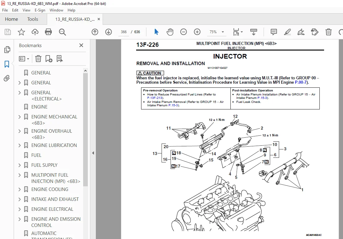
INJECTOR 366
REMOVAL AND INSTALLATION 366
REMOVAL SERVICE POINTS 367
INSTALLATION SERVICE POINTS 367
THROTTLE BODY ASSEMBLY 370
REMOVAL AND INSTALLATION 370
INSTALLATION SERVICE POINTS 371
ENGINE-ECU 372
REMOVAL AND INSTALLATION 372
INSTALLATION SERVICE POINTS 372
ENGINE COOLING 373
GENERAL INFORMATION 374
SERVICE SPECIFICATIONS 374
LUBRICANT 374
TROUBLESHOOTING 375
INSPECTION CHART FOR TROUBLE SYMPTOMS 375
SYMPTOM PROCEDURES 375
Inspection Procedure 1: Radiator Fan and Condenser Fan do not Operate 375
DIAGNOSIS PROCEDURE 375
STEP 1 Check the CAN bus system diagnosis 375
STEP 2 Check the MPI system actuator test 375
STEP 3 Check the MPI system diagnosis code 376
STEP 4 Check the A/T system diagnosis code 376
STEP 5 Check the A/C system diagnosis code 376
STEP 6 Check the ETACS system diagnosis code 376
STEP 7 Check the radiator fan relay, the condenser fan relay, and the fan control relay 376
STEP 8 Check the radiator fan motor and the condenser fan motor 376
STEP 9 Check of short to power supply, short to earth, open circuit and harness damage in power supply line between fusible link (SBF4) and radiator fan relay connector 376
STEP 10 Check of short to power supply, short to earth, open circuit and harness damage in power supply line between fusible link (SBF3) and condenser fan relay connector 376
STEP 11 Check of short to power supply, short to earth, open circuit and harness damage in power supply line between fusible link (SBF3) and fan control relay connector 376
STEP 12 Check of short to power supply, short to earth, open circuit and harness damage in power supply line between radiator fan relay connector and radiator fan motor connector 376
STEP 13 Check of short to power supply, short to earth, open circuit and harness damage in power supply line between radiator fan motor connector and fan control relay connector 377
STEP 14 Check of short to power supply, short to earth, open circuit and harness damage in power supply line between condenser fan relay connector and condenser fan motor connector 377
STEP 15 Check of short to power supply, short to earth, open circuit and harness damage in power supply and control line between fan control relay connector and condenser fan relay connector 377
STEP 16 Check of short to power supply, short to earth, open circuit and harness damage in body earth line between fan control relay and body earth 377
STEP 17 Check of short to power supply, short to earth, open circuit and harness damage in body earth line between condenser fan motor connector and body earth 377
STEP 18 Check of short to power supply, short to earth, open circuit and harness damage in F/LO line between radiator fan relay connector and ETACS-ECU connector 377
STEP 19 Check of short to power supply, short to earth, open circuit and harness damage in F/HI line between condenser fan relay connector and ETACS-ECU connector 377
STEP 20 Check the fusible link SBF3 and SBF4 377
STEP 21 Check the ETACS system diagnosis code 377
STEP 22 Check the MPI system actuator test 377
STEP 23 Check the symptoms 378
STEP 24 Check the symptoms 378
ON-VEHICLE SERVICE 378
ENGINE COOLANT CHANGE 378
COOLING FAN RELAY CONTINUITY CHECK 378
THERMOSTAT 379
REMOVAL AND INSTALLATION 379
REMOVAL SERVICE POINT 380
INSTALLATION SERVICE POINTS 380
INSPECTION 380
THERMOSTAT CHECK 380
WATER PUMP 381
REMOVAL AND INSTALLATION 381
WATER HOSE AND WATER PIPE 382
REMOVAL AND INSTALLATION 382
REMOVAL SERVICE POINTS 383
INSTALLATION SERVICE POINTS 383
RADIATOR 385
REMOVAL AND INSTALLATION 385
REMOVAL SERVICE POINT 386
INSTALLATION SERVICE POINT 386
INTAKE AND EXHAUST 387
GENERAL INFORMATION 388
SERVICE SPECIFICATIONS 388
AIR INTAKE PLENUM 389
REMOVAL AND INSTALLATION 389
INSTALLATION SERVICE POINT 390
INLET MANIFOLD 391
REMOVAL AND INSTALLATION 391
REMOVAL SERVICE POINTS 392
INSTALLATION SERVICE POINTS 392
EXHAUST MANIFOLD 394
REMOVAL AND INSTALLATION 394
REMOVAL SERVICE POINTS 396
INSTALLATION SERVICE POINTS 396
INSPECTION 396
AIR CLEANER 397
REMOVAL AND INSTALLATION 397
INSTALLATION SERVICE POINTS 397
EXHAUST PIPE AND MAIN MUFFLER 399
REMOVAL AND INSTALLATION 399
REMOVAL SERVICE POINTS 399
INSTALLATION SERVICE POINT 400
ENGINE ELECTRICAL 401
CHARGING SYSTEM 402
GENERAL INFORMATION 402
SPECIAL TOOL 402
ALTERNATOR ASSEMBLY 403
REMOVAL AND INSTALLATION 403
REMOVAL SERVICE POINTS 404
INSTALLATION SERVICE POINT 404
DISASSEMBLY AND REASSEMBLY 405
DISASSEMBLY SERVICE POINTS 406
REASSEMBLY SERVICE POINTS 406
INSPECTION 407
STARTING SYSTEM 409
GENERAL INFORMATION 409
STARTER MOTOR SPECIFICATIONS 409
SERVICE SPECIFICATIONS 409
ON-VEHICLE SERVICE 409
STARTER RELAY CONTINUITY CHECK 409
STARTER MOTOR ASSEMBLY 410
REMOVAL AND INSTALLATION 410
REMOVAL SERVICE POINT 410
STARTER MOTOR ASSEMBLY INSPECTION 411
DISASSEMBLY AND REASSEMBLY 413
DISASSEMBLY SERVICE POINTS 414
STARTER MOTOR PARTS CLEANING 414
REASSEMBLY SERVICE POINTS 414
INSPECTION 414
IGNITION SYSTEM 417
GENERAL INFORMATION 417
SERVICE SPECIFICATIONS 418
ON-VEHICLE SERVICE 418
IGNITION COIL CHECK 418
SPARK PLUG CHECK AND CLEANING 418
IGNITION COIL 419
REMOVAL AND INSTALLATION 419
CAMSHAFT POSITION SENSOR 420
REMOVAL AND INSTALLATION 420
REMOVAL SERVICE POINT 420
INSTALLATION SERVICE POINT 421
CRANK ANGLE SENSOR 421
REMOVAL AND INSTALLATION 421
DETONATION SENSOR 422
REMOVAL AND INSTALLATION 422
ENGINE AND EMISSION CONTROL 423
ENGINE CONTROL 424
GENERAL INFORMATION 424
CRUISE CONTROL 424
GENERAL INFORMATION 424
EMISSION CONTROL <MPI> 424
GENERAL INFORMATION 424
SERVICE SPECIFICATION(S) 424
VACUUM HOSE 425
VACUUM HOSE PIPING DIAGRAM 425
VACUUM CIRCUIT DIAGRAM 426
VACUUM HOSE CHECK 426
VACUUM HOSE INSTALLATION 426
CRANKCASE EMISSION CONTROL SYSTEM 427
GENERAL INFORMATION (CRANKCASE EMISSION CONTROL SYSTEM) 427
SYSTEM DIAGRAM 427
COMPONENT LOCATION (CRANKCASE EMISSION CONTROL SYSTEM) 427
EVAPORATIVE EMISSION CONTROL SYSTEM 428
GENERAL INFORMATION (EVAPORATIVE EMISSION CONTROL SYSTEM) 428
SYSTEM DIAGRAM 428
COMPONENT LOCATION (EVAPORATIVE EMISSION CONTROL SYSTEM) 428
PURGE CONTROL SYSTEM CHECK 428
REMOVAL AND INSTALLATION 429
EXHAUST GAS RECIRCULATION (EGR) VALVE 429
GENERAL INFORMATION (EXHAUST GAS RECIRCULATION SYSTEM) 429
OPERATION 429
SYSTEM DIAGRAM 429
COMPONENT LOCATION (EXHAUST GAS RECIRCULATION SYSTEM) 430
EXHAUST GAS RECIRCULATION VALVE (STEPPER MOTOR) CHECK 430
CHECKING THE OPERATION SOUND 430
CHECKING THE COIL RESISTANCE 430
OPERATION CHECK 430
CLEANING THE EXHAUST GAS RECIRCULATION VALVE 431
REMOVAL AND INSTALLATION 432
INSTALLATION SERVICE POINT 432
CATALYTIC CONVERTER 432
REMOVAL AND INSTALLATION 432
AUTOMATIC TRANSMISSION (FF) 433
AUTOMATIC TRANSMISSION (FF) 435
GENERAL INFORMATION 436
SPECIAL TOOLS 436
TROUBLESHOOTING 437
SHIFT PATTERN 437
UPSHIFT PATTERN 437
DOWNSHIFT PATTERN 437
DAMPER CLUTCH CONTROL 438
In 6th range 438
In 5th range 438
In 4th range 439
In 3rd range 439
CHECK CHART FOR DIAGNOSIS CODES 440
DIAGNOSIS CODE PROCEDURES 441
Code No P0962: Line Pressure Linear Solenoid Valve System (Short circuit) Code No P0963: Line Pressure Linear Solenoid Valve System (Open circuit) 441
DIAGNOSIS PROCEDURE 441
STEP 1 Check the A/T-ECU terminal voltage 441
STEP 2 Check for continuity in PLLS line between the A/T-ECU connector and A/T control solenoid valve assembly connector 441
STEP 3 Check the line pressure linear solenoid 441
STEP 4 Check for continuity in signal line between the A/T control solenoid valve assembly connector and the line pressure linear solenoid valve connector 441
STEP 5 Check the A/T-ECU and A/T control solenoid valve assembly connector pin terminals and the connection status 441
STEP 6 Check the A/T-ECU and A/T control solenoid valve assembly connector pin terminals and the connection status 441
STEP 7 Erase the diagnosis code, and drive the vehicle for a while 441
Code No P0973: Low Clutch Linear Solenoid Valve System (Short circuit) Code No P0974: Low Clutch Linear Solenoid Valve System (Open circuit) 442
DIAGNOSIS PROCEDURE 442
STEP 1 Check the A/T-ECU terminal voltage 442
STEP 2 Check for continuity in LOLS line between the A/T-ECU connector and A/T control solenoid valve assembly connector 442
STEP 3 Check the low clutch linear solenoid 442
STEP 4 Check for continuity in signal line between the A/T control solenoid valve assembly connector and the low clutch linear solenoid valve connector 442
STEP 5 Check the A/T-ECU and A/T control solenoid valve assembly connector pin terminals and the connection status 442
STEP 6 Check the A/T-ECU and A/T control solenoid valve assembly connector pin terminals and the connection status 442
STEP 7 Erase the diagnosis code, and drive the vehicle for a while 442
Code No P0976: 2-6 Brake Linear Solenoid Valve System (Short circuit) Code No P0977: 2-6 Brake Linear Solenoid Valve System (Open circuit) 443
DIAGNOSIS PROCEDURE 443
STEP 1 Check the A/T-ECU terminal voltage 443
STEP 2 Check for continuity in 26LS line between the A/T-ECU connector and A/T control solenoid valve assembly connector 443
STEP 3 Check the 2-6 brake linear solenoid 443
STEP 4 Check for continuity in signal line between the A/T control solenoid valve assembly connector and the 2-6 brake linear solenoid valve connector 443
STEP 5 Check the A/T-ECU and A/T control solenoid valve assembly connector pin terminals and the connection status 443
STEP 6 Check the A/T-ECU and A/T control solenoid valve assembly connector pin terminals and the connection status 443
STEP 7 Erase the diagnosis code, and drive the vehicle for a while 443
Code No P0979: 3-5 Reverse Clutch Linear Solenoid Valve System (Short circuit) Code No P0980: 3-5 Reverse Clutch Linear Solenoid Valve System (Open circuit) 444
DIAGNOSIS PROCEDURE 444
STEP 1 Check the A/T-ECU terminal voltage 444
STEP 2 Check for continuity in 35LS line between the A/T-ECU connector and A/T control solenoid valve assembly connector 444
STEP 3 Check the 3-5 reverse clutch linear solenoid 444
STEP 4 Check for continuity in signal line between the A/T control solenoid valve assembly connector and the 3-5 reverse clutch linear solenoid valve connector 444
STEP 5 Check the A/T-ECU and A/T control solenoid valve assembly connector pin terminals and the connection status 444
STEP 6 Check the A/T-ECU and A/T control solenoid valve assembly connector pin terminals and the connection status 444
STEP 7 Erase the diagnosis code, and drive the vehicle for a while 444
Code No P0982: High Clutch Linear Solenoid Valve System (Short circuit) Code No P0983: High Clutch Linear Solenoid Valve System (Open circuit) 445
DIAGNOSIS PROCEDURE 445
STEP 1 Check the A/T-ECU terminal voltage 445
STEP 2 Check for continuity in HCLS line between the A/T-ECU connector and A/T control solenoid valve assembly connector 445
STEP 3 Check the high clutch linear solenoid 445
STEP 4 Check for continuity in signal line between the A/T control solenoid valve assembly connector and the high clutch linear solenoid valve connector 445
STEP 5 Check the A/T-ECU and A/T control solenoid valve assembly connector pin terminals and the connection status 445
STEP 6 Check the A/T-ECU and A/T control solenoid valve assembly connector pin terminals and the connection status 445
STEP 7 Erase the diagnosis code, and drive the vehicle for a while 445
Code No P0998: Low Clutch Shift Solenoid Valve System (Short circuit) Code No P0999: Low Clutch Shift Solenoid Valve System (Open circuit) 446
DIAGNOSIS PROCEDURE 446
STEP 1 Check the A/T-ECU terminal voltage 446
STEP 2 Check for continuity in LCSS line between the A/T-ECU connector and the A/T control solenoid valve assembly 446
STEP 3 Check the low clutch shift solenoid 446
STEP 4 Check for continuity in signal line between the A/T control solenoid valve assembly connector and the low clutch shift solenoid valve connector 446
STEP 5 Check the A/T-ECU and A/T control solenoid valve assembly connector pin terminals and the connection status 446
STEP 6 Check the A/T-ECU and A/T control solenoid valve assembly connector pin terminals and the connection status 446
STEP 7 Erase the diagnosis code, and drive the vehicle for a while 446
Code No P099B: Low-Reverse Brake Shift Solenoid Valve System (Short circuit) Code No P099C: Low-Reverse Brake Shift Solenoid Valve System (Open circuit) 447
DIAGNOSIS PROCEDURE 447
STEP 1 Check the A/T-ECU terminal voltage 447
STEP 2 Check for continuity in LRSS line between the A/T-ECU connector and the A/T control solenoid valve assembly 447
STEP 3 Check the low-reverse brake shift solenoid 447
STEP 4 Check for continuity in signal line between the A/T control solenoid valve assembly connector and the low-reverse brake shift solenoid valve connector 447
STEP 5 Check the A/T-ECU and A/T control solenoid valve assembly connector pin terminals and the connection status 447
STEP 6 Check the A/T-ECU and A/T control solenoid valve assembly connector pin terminals and the connection status 447
STEP 7 Erase the diagnosis code, and drive the vehicle for a while 447
Code No P2763: Lock-up and Low-reverse Brake Linear Solenoid Valve System (Open circuit) Code No P2764: Lock-up and Low-reverse Brake Linear Solenoid Valve System (Short circuit) 448
DIAGNOSIS PROCEDURE 448
STEP 1 Check the A/T-ECU terminal voltage 448
STEP 2 Check for continuity in LULS line between the A/T-ECU connector and A/T control solenoid valve assembly connector 448
STEP 3 Check the lock-up and low-reverse brake linear solenoid 448
STEP 4 Check for continuity in signal line between the A/T control solenoid valve assembly connector and the lock-up and low-reverse brake linear solenoid valve connector 448
STEP 5 Check the A/T-ECU and A/T control solenoid valve assembly connector pin terminals and the connection status 448
STEP 6 Check the A/T-ECU and A/T control solenoid valve assembly connector pin terminals and the connection status 448
STEP 7 Erase the diagnosis code, and drive the vehicle for a while 448
DATA LIST REFERENCE TABLE 449
ON-VEHICLE SERVICE 449
ESSENTIAL SERVICE 449
A/T FLUID CHECK 449
A/T FLUID CHANGE 449
TRANSMISSION ASSEMBLY 450
REMOVAL AND INSTALLATION 450
REMOVAL SERVICE POINTS 451
INSTALLATION SERVICE POINTS 453
TRANSFER ASSEMBLY 454
REMOVAL AND INSTALLATION 454
REMOVAL SERVICE POINT 454
A/T FLUID COOLER LINE 455
REMOVAL AND INSTALLATION 455
AUTOMATIC TRANSMISSION OVERHAUL 457
GENERAL INFORMATION 458
OUTLINE OF CHANGE 458
GENERAL SPECIFICATIONS 458
TORQUE SPECIFICATIONS 459
TRANSMISSION 460
DISASSEMBLY AND REASSEMBLY 460
FRONT AXLE 469
GENERAL INFORMATION 470
DRIVESHAFT ASSEMBLY 470
REMOVAL AND INSTALLATION 470
DISASSEMBLY AND REASSEMBLY 472
EBJ BOOT REPLACEMENT 472
POWER PLANT MOUNT 473
GENERAL INFORMATION 474
ENGINE MOUNTING 474
REMOVAL AND INSTALLATION 474
CROSSMEMBER 475
REMOVAL AND INSTALLATION 475
SERVICE BRAKES 477
GENERAL INFORMATION 478
MASTER CYLINDER ASSEMBLY AND BRAKE BOOSTER ASSEMBLY 478
REMOVAL AND INSTALLATION 478
<VACUUM HOSE AND VACUUM PIPE> 478
INSTALLATION SERVICE POINTS 478
EXTERIOR 479
GENERAL INFORMATION 480
OUTLINE OF CHANGES 480
MARK 480
REMOVAL AND INSTALLATION 480
INSTALLATION SERVICE POINT 481
CHASSIS ELECTRICAL 483
GENERAL INFORMATION 484
OUTLINE OF CHANGE 484
BATTERY 484
ON-VEHICLE SERVICE 484
CHARGING 484
BATTERY TEST 484
TEST STEPS 484
STEP 1 Battery no-load voltage check 484
STEP 2 Battery charging 484
STEP 3 Load test check 484
HEATER, AIR CONDITIONER AND VENTILATION 487
GENERAL INFORMATION 488
OUTLINE OF CHANGE 488
ON-VEHICLE SERVICE 488
RELAY CHECK 488
A/C COMPRESSOR RELAY CONTINUITY CHECK 488
IDLE-UP INSPECTION 488
HEATER HOSE 489
REMOVAL AND INSTALLATION 489
COMPRESSOR ASSEMBLY 490
REMOVAL AND INSTALLATION 490
REMOVAL SERVICE POINTS 490
INSTALLATION SERVICE POINT 490
DISASSEMBLY AND REASSEMBLY 491
DISASSEMBLY SERVICE POINTS 492
REASSEMBLY SERVICE POINTS 492
REFRIGERANT LINE 494
REMOVAL AND INSTALLATION 494
REMOVAL SERVICE POINT 495
INSTALLATION SERVICE POINT 495
COMPONENT LOCATIONS 497
RELAY 498
SENSOR 499
SOLENOID AND SOLENOID VALVE 502
EARTH CABLE 503
EARTH 504
CONFIGURATION DIAGRAMS 505
OVERALL CONFIGURATION DIAGRAM <6B3> 506
ENGINE COMPARTMENT <6B3> 507
ENGINE AND TRANSMISSION <6B3> 509
CIRCUIT DIAGRAMS 511
CENTRALIZED JUNCTION 513
FUSIBLE LINK AND FUSE 513
CENTRALIZED RELAY 520
POWER DISTRIBUTION SYSTEM <4B1, 4J1, 6B3> 521
STARTING SYSTEM <6B3, 4B1, 4J1-CVT (VEHICLES WITHOUT AS&G SYSTEM)> 525
IGNITION SYSTEM <6B3> 526
CHARGING SYSTEM <4B1, 6B3 (LHD)> 528
ENGINE CONTROL SYSTEM <6B3> 530
COOLING SYSTEM <6B3> 534
A/T <6B3> 536
HEADLAMP <LHD> 539
TAIL LAMP, POSITION LAMP, LICENCE PLATE LAMP AND LAMP REMINDER BUZZER <LHD> 542
HEADLAMP MANUAL LEVELLING SYSTEM 546
HEADLAMP AUTOMATIC LEVELLING SYSTEM <LHD> 547
FRONT FOG LAMP 549
REAR FOG LAMP 551
ROOM LAMP, LUGGAGE COMPARTMENT LAMP AND IGNITION KEY CYLINDER ILLUMINATION LAMP 553
VANITY MIRROR LAMP 556
GLOVE BOX LAMP 557
TURN-SIGNAL LAMP AND HAZARD WARNING LAMP 558
STOP LAMP 560
BACK-UP LAMP <CVT, A/T> 561
HORN 562
METER AND GAUGE <LHD> 563
FUEL WARNING LAMP, OIL PRESSURE WARNING LAMP AND BRAKE WARNING LAMP <4B1, 4J1, 6B3 (LHD)> 565
POWER WINDOWS <LHD> 567
CENTRAL DOOR LOCKING SYSTEM <VEHICLES WITH KOS (LHD)> 569
ELECTRIC TAILGATE <LHD> 573
AIR CONDITIONER <4B1, 4J1, 6B3 (LHD)> 576
WINDSHIELD WIPER AND WASHER <LHD> 579
REAR WIPER AND WASHER 581
HEADLAMP WASHER 583
REAR WINDOW DEFOGGER 584
WIPER DEICER 585
HEATED DOOR MIRROR <LHD> 587
ELECTRIC RETRACTABLE REMOTE CONTROLLED MIRROR <LHD> 589
AUDIO SYSTEM <LHD> 592
MMCS <LHD> 596
HANDS-FREE INTERFACE SYSTEM 601
HANDS-FREE INTERFACE SYSTEM <VEHICLES WITHOUT MMCS (LHD)> 601
HANDS-FREE INTERFACE SYSTEM <VEHICLES WITH MMCS (LHD)> 604
ACCESSORY SOCKET AND CIGARETTE LIGHTER 607
ONE-TOUCH START SYSTEM (OSS) <4B1, 4J1, 6B3 (LHD)> 608
CRUISE CONTROL SYSTEM <4B1, 4J1, 6B3 (LHD)> 612
ACTIVE STABILITY CONTROL (ASC) AND HILL START ASSIST (HSA) <LHD> 614
ELECTRONIC CONTROLLED 4WD <LHD> 617
SUNROOF 619
SRS <LHD> 621
ELECTRIC POWER STEERING SYSTEM <LHD> 623
HEATED SEAT 625
POWER SEAT 627
REAR VIEW CAMERA <VEHICLES WITH DISPLAY AUDIO> 628
DOOR AJAR WARNING BUZZER <LHD> 629
PARKING BRAKE REMINDER BUZZER <LHD> 631
CAN <LHD> 633
SPARE CONNECTOR (FOR TRAILER LAMPS) 635
Customer Support: [email protected]
S.V 08/24