Description
Monogram Systems 15800 Vacuum Toilet Component Maintenance Manual with Illustrated Parts List
This is the complete Monogram Systems 15800 Vacuum Toilet Component Maintenance Manual with Illustrated Parts List, chapter 38-33-12, covering the toilet assembly Part Numbers 15800-012-1, 15800-012-2, 15800-019-1 and 15800-019-2 (cross-referenced to S 417T104-35/-36/-37/-38). The equipment covered is used on Boeing 747-400, 767 and 777 series aircraft vacuum waste systems, in both left-hand and right-hand pedestal configurations. If you are supporting cabin interior systems on these airframes, this Component Maintenance Manual gives you the manufacturer’s own disassembly, cleaning, inspection, repair, assembly, testing and parts-ordering data for the unit.
- Manual type: Component Maintenance Manual with Illustrated Parts List (ATA 38-33-12)
- Brand/model: Monogram Systems 15800 Vacuum Toilet Assembly
- Covered part numbers: 15800-012-1, 15800-012-2, 15800-019-1, 15800-019-2
- Aircraft application: Boeing 747-400, 767, 777
- Language: English
- Page count: 168 pages
- File format: PDF
- Document number: 38-33-12
- Revision: Revision 8, dated Apr 19/13
Chapters Covered
- Record of Revisions and Record of Temporary Revisions
- Service Bulletin List (15800-38-06 Rinse Valve Upgrade, 15800-38-51 Toilet Water Use Reduction)
- List of Effective Pages, Table of Contents, List of Figures, List of Tables
- Introduction — General, Layout of Manual, Revision Service, Shop Verification
- Description and Operation — General, Description, Operation, Leading Particulars
- Testing and Troubleshooting
- Test Equipment and Test Setup
- Test Procedures (Function Test, Current Draw Test, Fault Indicator Signal Test, Vacuum Blower Timing Test, Maintenance Switch Test, Flush Valve Leakage Test, Rinse Valve Leakage Test, Manual Valve Shut-Off Test, Water Consumption Test, Rinse Valve Drain Test, System Assembly Leakage Test, Rinse Valve Drying Procedure, Electrical Connector Test)
- Orbital Flush Valve Assembly Test Procedure (Functional Test, Electrical Test, Flush Valve Jamming, Flush Valve Leakage Test)
- Troubleshooting Table (flush no-start, insufficient rinse water, no drain, audible noise after cycle, bonding resistance faults)
- Disassembly — Toilet Assembly, Flush Control Unit, Orbital Slide Flush Valve Assembly, Rinse Valve Assembly
- Cleaning — cleaning materials and step-by-step cleaning procedure for bowl, flush valve, slide valve, anti-siphon valve, flush ring and rinse valve
- Check — visual inspection criteria and Inspection and Check table by part
- Repair — repair equipment and materials, blockage-clearing repair using Kinetic Water Ram
- Assembly — full reassembly of toilet assembly, flush control unit, orbital slide flush valve, motor-gear-switch assembly with limit switch adjustment, and rinse valve assembly, plus Storage Instructions
- Fits and Clearances — drain line interface dimensions and Recommended Torque Values table
- Special Tools, Fixtures, and Equipment — Kinetic Water Ram, test equipment list, and optional Vacuum Toilet Test Stand (VTTS)
- Illustrated Parts List — Vendor’s Code, Numerical Parts Index, and Detailed Parts List with Illustrations
Complete PDF Bookmark Tree
Complete Bookmarks
The complete bookmarks in the “Monogram Systems 15800 Vacuum Toilet Component Maintenance Manual with Illustrated Parts List (ATA 38-33-12)” are as follows:
TITLE PAGEp. 1
+VACUUM TOILET ASSEMBLYp. 1
RECORD OF REVISIONSp. 5
RECORD OF TEMPORARY REVISIONSp. 7
SERVICE BULLETIN LISTp. 9
LIST OF EFFECTIVE PAGESp. 11
TABLE OF CONTENTSp. 15
LIST OF FIGURESp. 17
LIST OF TABLESp. 19
+INTRODUCTIONp. 21
1. Generalp. 21
2. Layout of Manualp. 21
3. Revision Servicep. 21
4. Shop Verificationp. 21
+DESCRIPTION AND OPERATIONp. 23
+1. Generalp. 23
A. The vacuum toilet is actuated by depressing a 28 VDC electrical switch button in the aircraft lavatory. The switch signals the flush control unit (FCU) to initiate, monitor and sequence the flush cycle. At ground level or at altitudes below 16,000…p. 23
B. Each toilet assembly is self monitoring and outputs a signal if the flush valve is obstructed. It also has a maintenance button to aid the ground crew in clearing an obstruction.p. 23
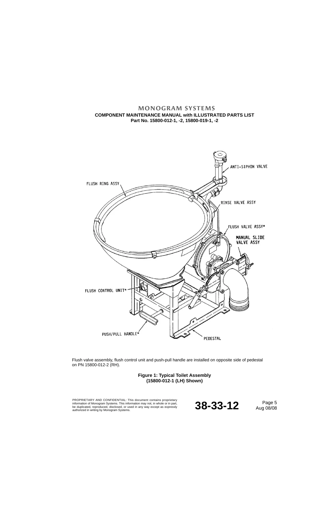
C. Each toilet assembly consists of major functional components easily removed and dismantled for service and repair or replacement. Components of the toilet assembly are the bowl and support pedestal, flush ring assembly, rinse valve assembly, antis…p. 23
+2. Descriptionp. 23
A. The toilet bowl is fabricated of stainless steel with a nonstick coating applied to the inside surface. The bowl mounts on a support pedestal constructed of stainless steel. The top of the bowl is large and has steep sides to allow waste to form a…p. 23
B. The flush ring assy, fabricated of stainless steel tubing and fitted with spray nozzles, is mounted on the upper rim of the bowl. The inlet of the ring connects to the antisiphon valve.p. 23
C. The antisiphon valve is designed to prevent pollution of the aircraft potable water supply by breaking contact of the fluid and providing an air gap which prevents reverse flow from the bowl. Rinse water is supplied to the antisiphon valve by the …p. 24
D. The rinse water valve is a solenoid controlled, self contained unit. The valve incorporates an integral water inlet fitting for the aircraft interface and a strainer.p. 24
E. The orbital slide flush valve assembly connects to the toilet bowl through an elbow. This valve is a motor-actuated, self-contained unit. The gate of the valve is a stainless steel circular plate with an eccentric hole matching, in diameter, the o…p. 24
F. The flush control unit is a modular electronic assembly mounted on the toilet support pedestal. Mounted on an electronic board inside the metal housing of the unit, a microcomputer chip monitors and controls operation of the toilet by timing and s…p. 24
G. The manual waste shut-off valve, on the downstream side of the flush valve, provides a back-up emergency method to shut off the flush line in the event of a flush valve failure. An outlet connects the outlet of the valve to the aircraft interface….p. 24
+3. Operationp. 25
A. Cabin/ambient differential pressure provides the vacuum to transport the waste material from the bowl to the holding tank in the aircraft at altitudes above 16,000 feet. At lower altitudes and ground operation, a vacuum blower provides the require…p. 25
B. Each toilet assembly is capable of detecting if the flush valve is jammed and cannot close. The jammed condition is detected by sensing an overload on the flush valve motor, or sensing that the limit switch has not been triggered. If the valve rem…p. 25
4. Leading Particularsp. 26
+TESTING AND TROUBLESHOOTINGp. 29
+1. Testingp. 29
A. Test Equipmentp. 29
B. Test Setupp. 30
C. Test Proceduresp. 31
D. End of Test Proceduresp. 35
+2. Flush Valve Assembly Test Procedurep. 40
A. Test Setupp. 40
B. Visual Inspectionp. 40
C. Functional Testp. 40
D. Electrical Testp. 40
+3. Troubleshootingp. 43
A. Troubleshoot the toilet assembly in accordance with Table 2.p. 43
+DISASSEMBLYp. 51
+1. Generalp. 51
A. Disassembly instructions given herein presume that complete overhaul of the toilet assembly is to be accomplished. Disassembly instructions cover disassembly only as far as practicable; however, these instructions enable disassembly to provide ade…p. 51
B. Prior to initiating disassembly operations, personnel shall carefully read all instructions and study illustrations applicable to the equipment undergoing overhaul. The toilet assembly shall be in a clean condition, free of contamination and resid…p. 51
C. The disassembly procedures for removal of major components and most detail parts are identical for all toilet assemblies included in this manual unless otherwise specified. Disassembly sequence is indicated by the index numbers shown in the illust…p. 51
D. Each of the following paragraphs describes disassembly of a toilet assembly or a component assembly.p. 51
E. Refer to Figure 301 whenever it becomes necessary to convert Toilet Assys PN 15800-012-1 to 15800-012-2 and 15800-019-1 to 15800-019-2.p. 51
+2. Parts Replacementp. 53
A. At each overhaul, O-rings, gaskets and attaching hardware shall be replaced, unless otherwise specified.p. 53
+3. Procedurep. 53
A. Disassemble Toilet Assembly (refer to IPL Figure 1).p. 53
B. Disassemble Toilet Assembly (refer to IPL Figure 1A).p. 56
C. Disassemble Flush Control Unit (refer to IPL Figure 2).p. 59
D. Disassemble Orbital Slide Flush Valve Assembly (refer to IPL Figure 3).p. 60
E. Disassemble Rinse Valve Assembly (refer to IPL Figure 4).p. 63
+CLEANINGp. 65
1. Generalp. 65
2. List of Materialsp. 65
+3. Cleaning Procedurep. 66
A. Remove the orbital slide flush valve, rinse valve, slide valve, flush ring, anti-siphon valve, and flush control unit from the toilet assembly (refer to DISASSEMBLY).p. 66
B. Support the bowl/pedestal over a suitable waste receptacle or drain. Clean the exterior and internal surfaces of the bowl and bowl elbow using a stiff bristled brush and a solution of hot soapy water and strong disinfectant.p. 66
C. Clean the orbital slide flush valve as follows:p. 66
D. Clean the slide valve as follows:p. 67
E. Clean the anti-siphon valve and flush ring as follows:p. 67
F. Clean the rinse valve as follows:p. 67
G. Ensure water inlet screen (207, IPL Figure 1 and 1A) is clean. Replace as necessary.p. 68
H. Using lint-free cloth, moistened with isopropyl alcohol (Table 401), wipe electrical parts clean.p. 68
I. Dry clean parts by wiping with dry, lint-free cloth or by blowing dry with low pressure compressed air.p. 68
J. Install the orbital slide flush valve, rinse valve, slide valve, flush ring, anti-siphon valve, and flush control unit on the toilet assembly (refer to ASSEMBLY).p. 68
+CHECKp. 69
+REPAIRp. 73
+1. Generalp. 73
A. Except for permissible repairs outlined in this section, repair of the toilet assembly is not considered practical. Parts which do not meet inspection or functional requirements shall be replaced.p. 73
B. Refer to the section on CLEANING before performing repair procedures.p. 73
C. All nuts, washers, gaskets, and O-rings removed during disassembly shall be replaced regardless of condition.p. 73
D. A damaged or torn rinse valve assembly screen shall be replaced.p. 73
E. All damaged or otherwise illegible part number identification shall be replaced.p. 73
F. Test after Repairp. 73
+2. Equipment and Materialsp. 73
A. Standard shop equipment and tools, along with tools and materials listed in Table 601 can be used to repair this unit.p. 73
B. Required Materialsp. 74
+3. Component and Sub-Assembly Repairsp. 76
A. Toilet Bowlp. 76
B. Flush Control Unitp. 78
C. Printed Circuit Boardp. 79
+4. Toilet Blockage Removalp. 80
A. Manual Removalp. 80
B. Using the Kinetic Water Ram Toolp. 80
+ASSEMBLYp. 83
+1. Generalp. 83
A. Assembly instructions given herein presume the toilet assembly has been disassembled to the extent covered in DISASSEMBLY. All part number identification removed during cleaning or otherwise illegible, has been replaced during repair. All new part…p. 83
B. If a unit has been subjected to a partial overhaul only, disregard those instructions that are not applicable. Refer to Table 701 for assembly materials. The assembly instructions detailed in the following paragraphs apply equally to those assembl…p. 83
C. Perform the appropriate TESTING procedures after assembly to verify proper operation.p. 83
D. Each of the following paragraphs describes assembly of a toilet assembly or a component assembly. The corresponding exploded view illustration figure is listed in the paragraph heading.p. 83
E. Refer to Figure 701 whenever it becomes necessary to convert Toilet Assys PN 15800-012-1 to 15800-012-2 and 15800-019-1 to 15800-019-2.p. 83
2. List of Tools and Materialsp. 85
+3. Proceduresp. 87
A. Assemble toilet assembly (refer to IPL Figure 1).p. 87
B. Assemble toilet assembly (refer to IPL Figure 1A).p. 90
C. Assemble Flush Control Unit (refer to IPL Figure 2).p. 93
D. Orbital Slide Flush Valve Assembly (refer to IPL Figure 3)p. 94
E. Rinse Valve Assemblyp. 102
+4. Storage Instructionsp. 104
A. When the toilet assembly is to be stored after overhaul, all openings shall be sealed and, if possible, placed into the original shipping container. If the shipping container is not available, a wooden framework may be built around the toilet asse…p. 104
B. When a component of the toilet is to be stored after overhaul, it should be placed in the original shipping carton. If the original carton is unavailable, wrap the component with barrier material and place it in a suitable container. The part numb…p. 104
+FITS AND CLEARANCESp. 105
+1. Generalp. 105
A. Refer to Figure 801 to determine proper orientation of bowl elbow for -1 (LH) and -2 (RH) configurations.15800-012-1 & -019-1 (LH) and 15800-012-2 & -019-2 (RH).p. 105
B. In case the toilet assembly was completely reassembled, refer to Figure 802 for toilet drain elbow and aircraft drain line interface dimensions.p. 106
C. Torque Tablep. 108
+SPECIAL TOOLS, FIXTURES, AND EQUIPMENTp. 109
+1. Special Toolsp. 109
A. Kinetic Water Ram PN 14400-995 may be used to remove toilet blockage caused by toilet tissues, paper napkins, paper towels etc. Refer to REPAIR for more information on this optional tool.p. 109
2. Fixturesp. 109
3. Special Equipmentp. 109
+4. Optional Test Equipmentp. 110
A. Vacuum Toilet Test Standp. 110
+ILLUSTRATED PARTS LISTp. 111
1. Purposep. 111
+2. Scope of Informationp. 111
A. Assembly Relationshipp. 111
B. How to Identify a Partp. 111
C. Effectivityp. 111
D. Abbreviationsp. 112
E. Symbolsp. 113
3. Vendor's Codep. 113
4. Numerical Parts Indexp. 116
+5. Detailed Parts List with Illustrationsp. 129
IPL Figure 1: Toilet Assemblyp. 130
IPL Figure 1A: Toilet Assemblyp. 138
IPL Figure 2: Flush Control Unitp. 146
IPL Figure 3: Orbital™ Slide Flush Valve Assemblyp. 151
IPL Figure 4: Rinse Valve Assemblyp. 156
IPL Figure 5: Motor Assemblyp. 160
IPL Figure 6: Printed Wiring Board Assemblyp. 162
IPL Figure 7: Filter Board Assemblyp. 166
Taken together, these sections walk a technician through the entire life cycle of the 15800 vacuum toilet: understanding how the flush cycle, rinse valve, orbital slide flush valve and flush control unit work together, testing the unit against factory-specified pressures, currents and timings, tearing it down to component level, cleaning and inspecting every part against the manufacturer’s criteria, repairing and reassembling it with the correct torque values and adjustment clearances, and ordering the exact replacement parts by number.
Why This Monogram 15800 Vacuum Toilet Manual Matters for Your Shop
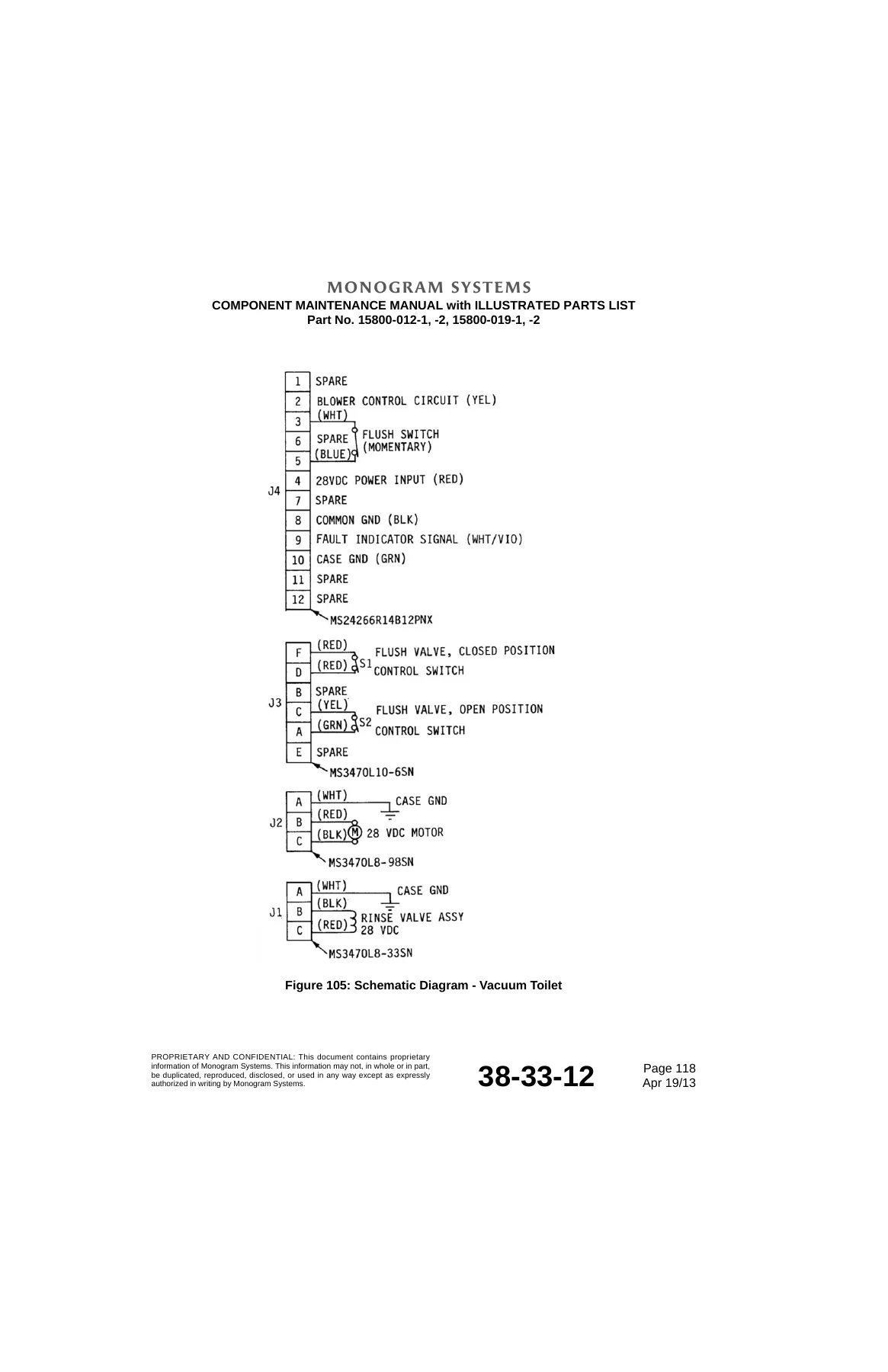
The Monogram Systems 15800 Vacuum Toilet Component Maintenance Manual is built around the specific electrical, pneumatic and hydraulic values this unit was designed to run at — 28 VDC actuation, an 8.6 psid vacuum reference, a 34 psi water inlet, a 1.2-second rinse cycle and a 4.0-second flush valve open time. Working from generic troubleshooting or a different toilet’s documentation risks misdiagnosing a jammed flush valve, an out-of-spec rinse valve, or a limit switch that needs the 0.031 to 0.081 inch clearance called out in the assembly procedure. This manual gives you the manufacturer’s own test setups (Figures 101 through 107), the full Troubleshooting Table for symptoms like “toilet flushes but does not drain” or “audible noise after completion of flush cycle does not stop,” the Recommended Torque Values table in both lbf-in and N-m, and the Illustrated Parts List needed to identify and requisition every bolt, seal, gear and valve component by part number.
Because this is a delivered PDF, there’s no shipping wait and no missing pages: download the Monogram Systems 15800 Vacuum Toilet Component Maintenance Manual with Illustrated Parts List immediately after purchase, open it on a laptop, tablet or shop PC, and print any page you need at the bench.

Reviews
There are no reviews yet.