
Mooney M20K Service and Maintenance Manual MAN134 Rev B – 1997-2014 PDF
Original price was: $39.95.$24.95Current price is: $24.95.
Mooney M20K Service and Maintenance Manual, P/N MAN134 Revision B (original issue September 1997, Revision B May 2014). 550-page PDF covering airworthiness limitations, time limits, scheduled inspections, airframe standard practices, flight controls, fuel, landing gear, electrical power, propellers and powerplant for M20K 231, 252, TSE and Encore serials 25-0001 and ON.
Description
Mooney M20K Service and Maintenance Manual – MAN134 Rev B
This is the complete Mooney M20K Service and Maintenance Manual, published by Mooney International Corporation under part number MAN134. The original issue dates to September 1997, with Revision A in March 2000 and Revision B in May 2014. It is the manual a shop reaches for when an M20K needs inspection, rigging, torque values, scheduled servicing, or a system-level repair decision – not a generic light-aircraft guide, but a document written around one airframe and its serial-number break points.
The Mooney M20K Service and Maintenance Manual covers the four-place high-performance turbocharged single from serial 25-0001 and ON, including the 231, 252, TSE and Encore variants. Because Mooney changed systems and equipment across the production run, the manual flags where a procedure applies only to a limited serial range – so the correct instructions follow the aircraft you actually own, not an averaged-out version of the fleet.
File Details
- Manual type: Service and Maintenance Manual
- Brand / manufacturer: Mooney International Corporation (Mooney Aircraft Corporation)
- Model: M20K
- Part number: MAN134
- Revision: Revision B (original issue September 1997; Revision A March 2000; Revision B May 2014)
- Serial number effectivity: 25-0001 and ON
- Language: English
- Page count: 550 pages
- File format: PDF
Chapters Covered
- Chapter 4 – Airworthiness Limitations (FAA-approved section, component replacement)
- Chapter 5 – Time Limits / Maintenance Checks: time limit components, scheduled maintenance checks, inspection check points, torque tables, aircraft file inspection, engine functional check, 25-hour, 50-hour and 100-hour (or annual) inspections, access cover ID, lubrication and service guide, viscosity requirements
- Chapter 6 – Dimensions and Areas: aircraft specifications, aircraft dimensions, aircraft stations
- Chapter 7 – Lifting and Shoring: jacking
- Chapter 8 – Leveling and Weighing: leveling, weight and balance, Charlie Weight installation
- Chapter 9 – Towing and Taxiing: ground handling, towing, warmup and taxiing, emergency procedures
- Chapter 10 – Parking and Mooring: parking, flyable storage, prolonged storage, return to service, mooring
- Chapter 11 – Placards and Markings
- Chapter 12 – Servicing: servicing intervals, fuel tanks, fuel drains, engine oil, oxygen system, induction air filter, battery, tires and wheels, brake reservoir, hydraulic brake bleeding, cleaning
- Chapter 20 – Standard Practices – Airframe: skin specifications, corrosion detection and prevention, painting
- Chapter 21 – Environmental Systems: cabin ventilation, heating
- Chapter 24 – Electrical Power: DC generation, alternator charging system maintenance, voltage regulator maintenance, battery maintenance, warning circuits, powerplant circuits, low battery starting, lighting circuits, landing gear circuits, fuel system circuits, miscellaneous circuits, troubleshooting charts, electrical load distribution
- Chapter 27 – Flight Controls: aileron system, rudder and steering system, elevator system, variable downspring system, stabilizer trim system, trim troubleshooting, wing flap system, aileron/rudder interconnect, control surface static balancing, trailing edge, stall warning maintenance and troubleshooting, speed brake systems (Series 100 and Series 2000)
- Chapter 28 – Fuel: storage, fuel tank field repair, fuel tank leak repair, soapless bubble fluid formula, fuel additives, distribution, boost pump removal and installation, gascolator screen cleaning, fuel injection system, engine priming, selector valve, dump, drains, vents, indicating, quantity transmitter adjustment, gauge adjustment, flared fittings
- Chapter 30 – Ice Protection: pitot description and operation, propellers, propeller de-ice service guide, troubleshooting chart, ammeter test, de-icer timer check, heat test, continuity test, brush to slip ring resistance test, brush assembly resistance check, brush replacement and alignment, slip ring alignment, servicing and cleaning
- Chapter 32 – Landing Gear: main landing gear and doors, nose gear and doors, extension and retraction, main and nose gear system rigging, emergency gear extension system rigging, landing gear actuator and clutch, manual emergency gear extension, troubleshooting, wheels and brakes, brake system break-in, steering, position and warning, shock disc inspection, recommended hard landing inspection
- Chapter 34 – Navigation: pitot and static air pressure system, directional gyro compass
- Chapter 35 – Oxygen
- Chapter 37 – Vacuum: distribution, indicating
- Chapter 39 – Electrical Panels and Components: instrument and control panels, electrical and electronics equipment racks
- Chapter 51 – Structures: structural repair general
- Chapter 52 – Doors: cabin door, baggage compartment door
- Chapter 53 – Fuselage: main frame, auxiliary structure, plates/skin, attach fittings, fillets/fairings
- Chapter 55 – Stabilizers: horizontal stabilizer, elevator, vertical stabilizer, rudder
- Chapter 56 – Windows: windshield and cabin windows, plexiglas drilling
- Chapter 57 – Wings: plates/skins, attach fittings, flight surfaces
- Chapter 60 – Standard Practices – Propeller
- Chapter 61 – Propellers: propeller assembly, controlling
- Chapter 71 – Powerplant: cowling
- Chapter 72 – Engine – Reciprocating
- Chapter 73 – Engine Fuel System: distribution, controlling, indicating
- Chapter 74 – Ignition: power control, emergency shutdown
- Chapter 76 – Engine Controls: rigging
- Chapter 77 – Engine Indicating: power, temperature
- Chapter 78 – Exhaust: installation, servicing, replacement components
- Chapter 79 – Oil: storage, distribution, indicating
- Chapter 80 – Starting: cranking
- Chapter 81 – Turbines: power recovery turbocharger
- Chapter 91 – Schematics: electrical system hardware charts (14V and 28V), schematics, special equipment
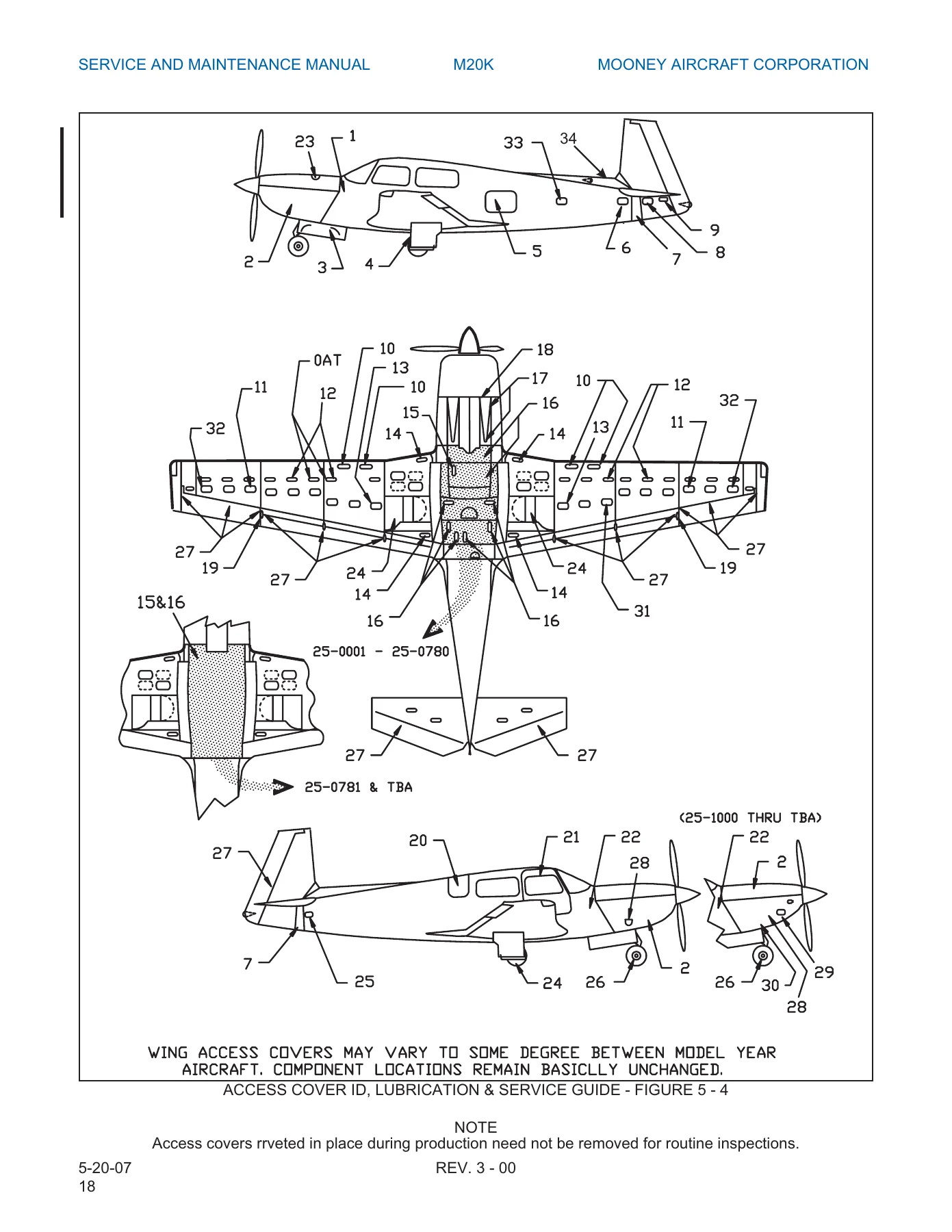
What makes this manual useful is not the chapter list – it is the detail inside it. Chapter 5 alone carries the full inspection logic: the one-time 25-hour check, the repetitive 50-hour, and the 100-hour or annual inspection, each broken into engine, propeller, cabin, landing gear, wings, fuselage and empennage. The same chapter includes the flare nut torque table, metric bolt torque tables, AN/MS standard bolt torque tables with the friction drag torque method, and the access cover identification, lubrication and service guide keyed to a lubrication symbol legend. That combination – inspection sequence plus fastener and lubricant data in one place – is what turns a manual into a working document rather than a reference book.
Systems and Procedures
The airframe content is practical and specific. Chapter 20 gives wing, fuselage and empennage skin panel thickness and material callouts, then walks through the four forms of aluminum corrosion – chemical, local-cell (including intergranular and exfoliation), concentration cell, and galvanic – with the removal and zinc chromate treatment procedure for each. The painting section covers urethane enamel repair, wipe solvents, wash primer, and the requirement to strip and rebalance any control surface before flight after repainting.
Flight controls are treated as a rigging exercise, not just a parts list. Aileron rigging is split by serial number (25-0001 through 25-0785 and 25-0786 and ON, with the later aircraft using 3/16 inch rig pins at the jackshaft and bellcranks). Rudder rigging covers nose wheel centering, steering linkage adjustment, rudder stop travel at 23 degrees right and left, and the .020 inch clearance check between the steering stop and gear truss on 25-0824 and ON. Elevator, stabilizer trim, flap, and the aileron/rudder interconnect are each handled with their own travel values and adjustment points.
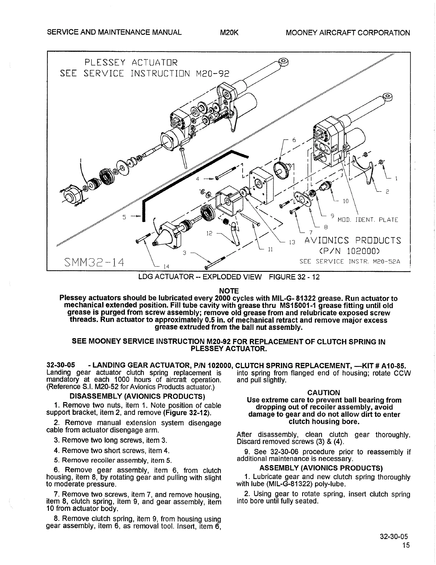
Landing gear gets unusually thorough coverage. The manual splits main gear rigging by serial range, explains the actuator barrel nut and mechanical down stop and up stop clearances, the nose gear bungee deflection window of .030 to .070 inches, and the main gear overcenter preload measurement using the rigging tool and a 10-inch torque wrench with shim stock – with a target of 250 to 280 inch pounds and a 325 inch pound ceiling after electrical extension. Emergency gear extension system rigging and the Avionics Products actuator clutch spring replacement round out the chapter.
Fuel system work is equally detailed: integral tank field repair with approved sealants, mixing and application lives, fillet sealing, leak classification by wetted area (stain, seep, heavy seep, running leak), internal and external leak detection, and temporary versus permanent fastener leak repair. Fuel quantity transmitter adjustment is given separately for 25-0001 through 25-0446 and 25-0447 and ON, with unusable fuel quantities and gauge tolerance.
Electrical content goes well beyond a schematic folder. The alternator charging system servicing precautions, voltage regulator bench and on-aircraft adjustment, battery removal and cleaning, annunciator troubleshooting down to individual component and assembly references, current sensor adjustment for 25-2000 and later, and the low boost pump adjustment procedures split by serial range are all included.
IMAGES PREVIEW
Who This Manual Is For
This Mooney M20K service and maintenance manual suits the A&P mechanic performing annual or 100-hour inspections, the owner-assisted maintenance provider working under supervision, and the M20K owner who wants to understand what the shop is doing and why. It also supports the shop that has just taken on an M20K and needs the serial-number-specific rigging and torque data rather than a generic Mooney reference.
The manual assumes a reader who already understands aircraft maintenance practice. It provides Mooney-specific values, sequences, and clearances, and it points to vendor publications where appropriate – TCM overhaul and operators manuals for the TSIO-360 series, McCauley and Hartzell propeller documents, Bendix and Slick magneto service data, RAJAY/Rotomaster and Garrett Airesearch turbocharger manuals, and B.F. Goodrich propeller de-ice reports.
Why It Matters
An M20K is a turbocharged, retractable-gear, high-performance single with a laminar-flow wing and a pivoting-empennage trim system. The rigging values are tight, the gear preload window is narrow, and the control surface balance limits are non-negotiable. Working from the wrong serial range or an approximated torque figure is how small jobs become expensive ones. This manual gives the exact figures Mooney published for each serial block, so the work is done to the aircraft’s actual configuration.
It also gives you the paperwork side: airworthiness limitations, component replacement and overhaul times, life-limited items, and the inspection intervals that keep the aircraft compliant.
Instant PDF Delivery
You get the complete 550-page Mooney M20K Service and Maintenance Manual as a PDF, delivered immediately after checkout. There is no shipping, no waiting for a printed binder, and no risk of a lost page. Open it on a laptop in the hangar, a tablet on the wing, or a phone at the parts counter. Print the inspection checklist, the torque table, or the rigging page you are working from and take it to the aircraft – and reprint it whenever it gets greasy.
Reviews
There are no reviews yet.