
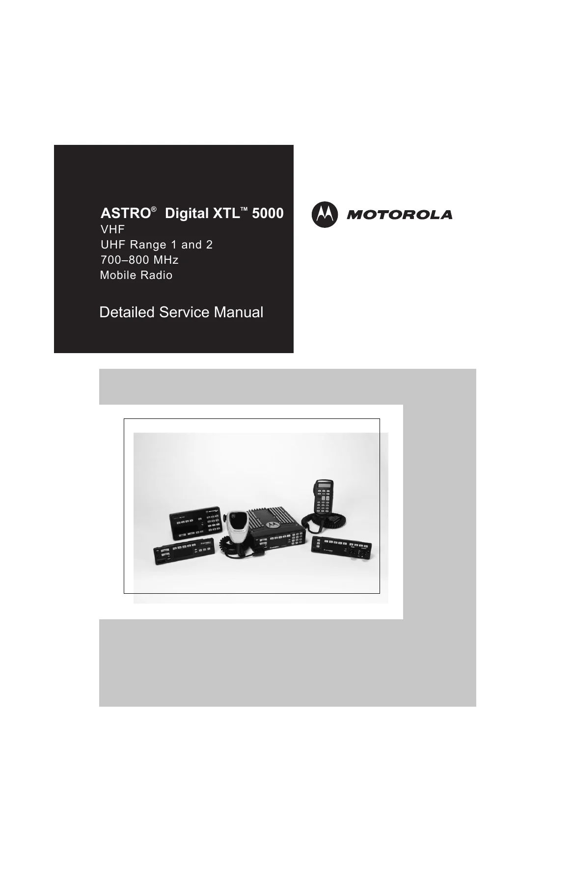
Motorola ASTRO Digital XTL 5000 VHF UHF 700-800 MHz Mobile Radio Detailed Service Manual 6881096C74-B
Original price was: $59.95.$34.95Current price is: $34.95.
Complete 528-page Motorola ASTRO Digital XTL 5000 mobile radio detailed service manual (6881096C74-B) covering VHF, UHF Range 1, UHF Range 2 and 700-800 MHz models with W3, W4, W5, W7 or W9 control heads. Component-level schematics, troubleshooting charts, waveforms and parts lists. Instant PDF download.
Description
Motorola ASTRO Digital XTL 5000 Mobile Radio — Detailed Service Manual (6881096C74-B)
When a Motorola XTL 5000 mobile radio comes across the bench with a fault that a board swap won’t cure, this is the manual you open. Published by Motorola in May 2005 under publication number 6881096C74-B, this 528-page detailed service manual takes the technician from block-level understanding down to individual component diagnosis across the full XTL 5000 mobile radio family — VHF (136–174 MHz), UHF Range 1 (380–470 MHz), UHF Range 2 (450–520 MHz), and 700–800 MHz. It covers radios fitted with the W3, W4, W5, W7, or W9 control head.
This is not the basic service manual. Where the basic manual helps you identify a suspect board, this detailed edition gives you the schematics, the bias tables, the switching logic, the injection levels, and the failure signatures needed to repair at component level — the same depth of information Motorola service depots work from.
File Details
- Manual type: Detailed Service Manual (component-level)
- Brand: Motorola
- Model: ASTRO Digital XTL 5000 Mobile Radio
- Bands covered: VHF 136–174 MHz · UHF Range 1 380–470 MHz · UHF Range 2 450–520 MHz · 700–800 MHz
- Control heads: W3, W4, W5, W7, W9
- Language: English
- Page count: 528
- File format: PDF
- Document number: 6881096C74-B
- Edition: 6881096C74-B — added VHF High Power and UHF R1 High Power models
- Publication date: May 25, 2005
Chapters Covered
- Chapter 2 — Product Overview
- Chapter 3 — Theory of Operation
- Chapter 4 — Troubleshooting Procedures
- Chapter 5 — Troubleshooting Charts
- Chapter 6 — Troubleshooting Waveforms
- Chapter 7 — Schematics, Component Location Diagrams, and Parts Lists
- Chapter 8 — Interconnect Boards Schematics, Component Location Diagrams, and Parts Lists
- Chapter 9 — Flex Cable Pin-Out Lists
- Appendix A — Secure Modules
- Appendix B — Replacement Parts Ordering
- Glossary and Index
What Chapter 2 Covers — Product Overview
The overview chapter breaks the radio into its functional blocks and explains how they relate: control-head assembly, radio power distribution, receiver front-end and back-end, transmitter, frequency generation unit, and controller. The Vehicle Interface Port (VIP) section is covered in full — dash-mount, remote-mount, W3 hand-held, and remote-plus-DEK configurations — with male and female pin-out diagrams, relay connection guidance, and the DEK interface signals (DATA IN, DATA OUT, STROBE, CLOCK). Ignition-sense circuitry and the power-supply scheme are also described here.
What Chapter 3 Covers — Theory of Operation
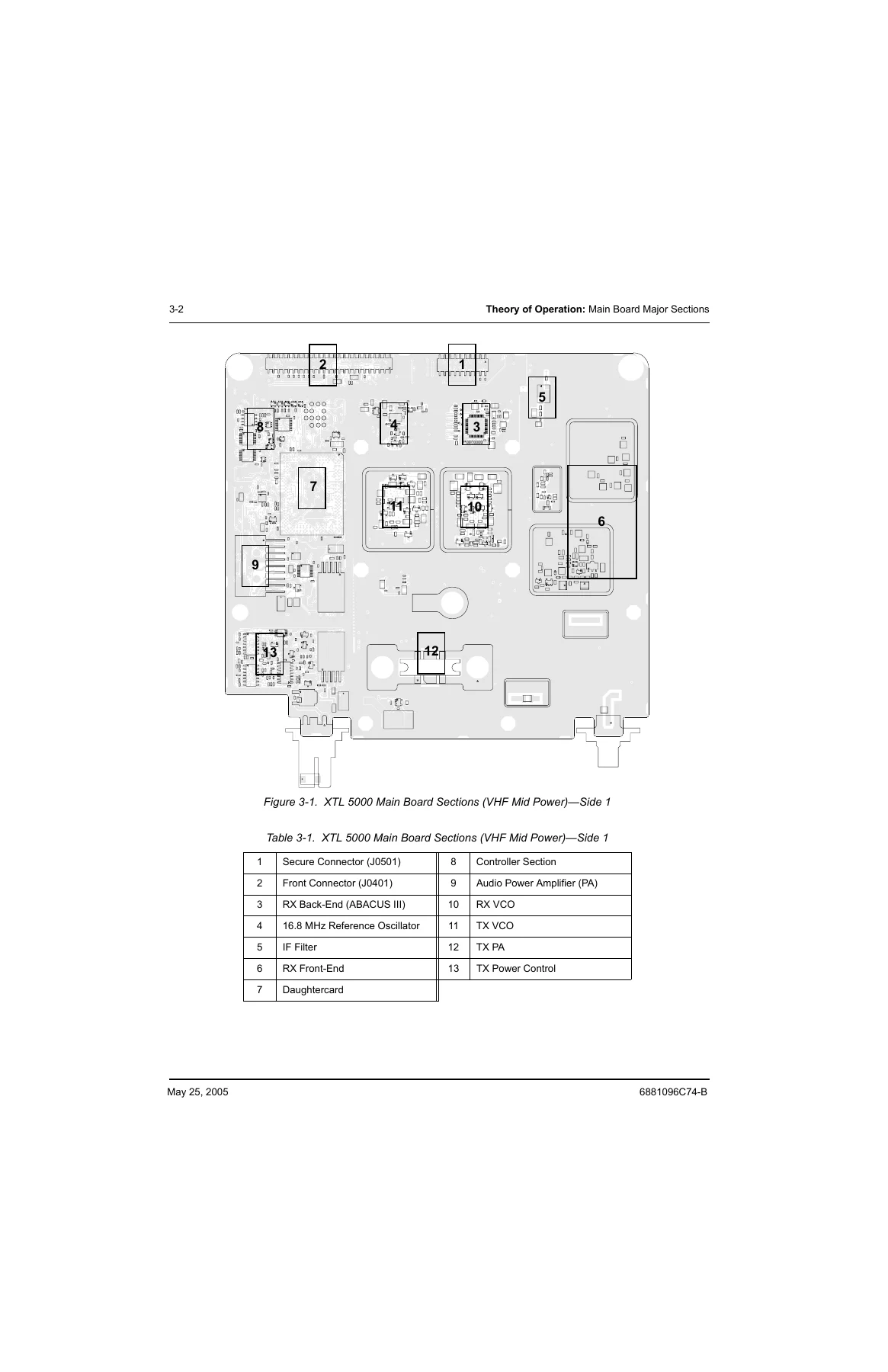
Chapter 3 is the heart of the manual. It provides a circuit-by-circuit description of the main board for every frequency band. In the receiver front-end you get the 15 dB step attenuator, PIN diode switching, preselector filters, low-noise amplifiers, image filters, and the double-balanced mixer. The receiver back-end section covers the crystal IF filters, the IF amplifier, and the ABACUS III (AD9874) digitizing subsystem with its second local oscillator and sampling clock oscillator. The transmitter section details the RF power amplifier gain stages for every power class — 50 W and 100 W VHF, 40 W and 100 W UHF Range 1, 45 W UHF Range 2, and 35 W 700–800 MHz — along with the output network, harmonic filter, power detector, and the full power-control loop with its protection mechanisms. The frequency generation unit chapter describes the reference oscillator, the LV Frac-N synthesizer, the voltage multiplier, the superfilter, modulation, charge-pump bias, loop filter, lock detect, injection strings, and the VCOs for each band. The controller section covers the daughtercard, DC power distribution, encryption voltages, reset circuits, power-up and power-down sequencing, system clocks, the RS-232/USB bus, the SB9600 external bus, the SPI bus, and both receive and transmit audio paths.
What Chapter 4 Covers — Troubleshooting Procedures
Chapter 4 converts theory into procedure. It opens with handling precautions for CMOS and ESD-sensitive devices, then covers voltage measurement and signal tracing. Power-up self-check error codes and operational error codes are tabulated with corrective actions. The main board troubleshooting sections are band-specific: VHF (136–174 MHz), UHF Range 1 (380–470 MHz), UHF Range 2 (450–520 MHz), and 700–800 MHz. Each band section addresses the FAIL 001 (synthesizer out-of-lock) condition, VCO hybrid assembly notes, out-of-lock diagnosis, FGU troubleshooting aids, no or low output power, no or low modulation, and back-end faults. Standard bias tables list the expected voltages on power lines, clock and control lines, audio lines, and VIP lines, with specific probe locations and signal states.
What Chapters 5 and 6 Cover — Troubleshooting Charts and Waveforms
Chapter 5 is a flowchart library. Dozens of charts guide you step by step through poor RX sensitivity, no RX audio, RX IF and back-end SINAD failures, low or no RX/TX injection, VCO unlock, RFPA output faults, power-control faults (no VGBIAS, no K9.1V, no or low RFPA_CNTRL), and TX audio loss — all organized by frequency band. Chapter 6 provides reference waveforms for the signals you will probe: power-on reset timing, power-down reset, the 16.8 MHz and 32 kHz clocks, the SPI bus, SB9600 waveforms, RS-232 and USB traffic, the serial audio port, the secure interface, and the RX/TX audio paths with a 1 kHz test tone. Tables give typical peak-to-peak and DC bias values at each test point.
What Chapters 7, 8, and 9 Cover — Schematics, Boards, and Flex Cables
Chapter 7 is the complete schematic package for the VHF (HUD4022A/HUD4025B), UHF Range 1 (HUE4039A/HUE4043A), UHF Range 2 (HUE4040A), and 700–800 MHz (HUF4017A) main boards. Each board gets a full set of schematics — controller, audio, power control, FGU, VCOs, receiver front-end and back-end, IF, RF power amplifier, output network, accessory connector, control-head connector, and secure interface — plus side-1 and side-2 board layouts and a complete parts list with Motorola part numbers. Chapter 8 covers the interconnect boards: the standard W4/W5/W7/W9 remote board, the motorcycle board, the W3 hand-held board, and the high-power remote board, with schematics, component-location diagrams, and parts lists. It also includes the secure interface board layouts and the motorcycle signal-routing diagram. Chapter 9 lists the flex cable pin-out assignments for mid-power dash, mid-power rear accessory, mid-power remote, and high-power remote configurations.
Secure Modules and Parts Ordering
Appendix A covers the Universal Crypto Module (UCM) kits and secure interface boards used with secure-equipped XTL 5000 radios. It explains the encryption IC and key-variable loading, the SSI bus communication between the host processor and the secure module, and the troubleshooting paths for Error 09/10, Error 09/90, Error S03, and keyload failure. Appendix B provides the complete replacement-parts ordering procedure, including Motorola Online, mail, telephone, and fax ordering channels, parts identification, and product customer service contacts.
Why This Manual Is the Right Reference for XTL 5000 Repair
Component-level faults on a professional mobile radio rarely resolve with a board swap. The XTL 5000 is a synthesized, microcontroller-based transceiver with a DSP, multiple VCOs, a digital back-end IC, and a power-control loop with temperature and current protection. Isolating a fault to a single stage means knowing the expected bias voltages, the switching logic states, the injection levels, the loop filter behaviour, and the failure signatures for each section. This manual gives you all of that, band by band, with the schematics and parts lists to support a real repair — not just a guess. The troubleshooting charts are built around the actual test points on the board, and the standard bias tables tell you what a healthy radio should read before you start probing.
IMAGES PREVIEW
Instant PDF Download
The complete Motorola ASTRO Digital XTL 5000 detailed service manual (publication 6881096C74-B) is delivered as a single PDF, ready to download immediately after payment. No shipping, no waiting for a physical book, no media to lose. Read it on a laptop, tablet, or phone at the bench, or print the schematics and troubleshooting charts you need and keep them next to the radio. Whether the job is a FAIL 001, a dead receiver, a power amplifier that will not make rated output, or a controller that will not boot, the information is in your hands as soon as payment clears.
Reviews
There are no reviews yet.