Trusted Business
Verified & Licensed
Virus Free Files
100% Safe Downloads
Secure Payment
SSL Protected
Instant Delivery
Available Immediately
MTU ADEC & SAM connection interface Series 2000 unit-pump system Series 4000 System documentation Manual E532304-00E PDF DOWNLOAD
$28.95
MTU ADEC & SAM connection interface Series 2000 unit-pump system Series 4000 System documentation Manual E532304-00E PDF DOWNLOAD
ADEC and SAM connection interface
Series 2000 unit-pump system, Series 4000
Application: Genset (SAM “advanced”)
Instant PDF Download
Available immediately
Save to Your Device
Download & keep forever
Antivirus Scanned
100% virus-free
Trusted Worldwide
175,000+ customers
Description
MTU ADEC & SAM connection interface Series 2000 unit-pump system Series 4000 System documentation Manual E532304-00E PDF DOWNLOAD
FILE DETAILS:
MTU ADEC & SAM connection interface Series 2000 unit-pump system Series 4000 System documentation Manual E532304-00E PDF DOWNLOAD
Language : English
Pages : 202
Downloadable : Yes
File Type : PDF
IMAGES PREVIEW OF THE MANUAL:
Questions? Email us: [email protected]
https://vimeo.com/858875996?share=copy
TABLE OF CONTENTS:
MTU ADEC & SAM connection interface Series 2000 unit-pump system Series 4000 System documentation Manual E532304-00E PDF DOWNLOAD
ADEC and SAM connection interface
Series 2000 unit-pump system, Series 4000
Application: Genset (SAM “advanced”)
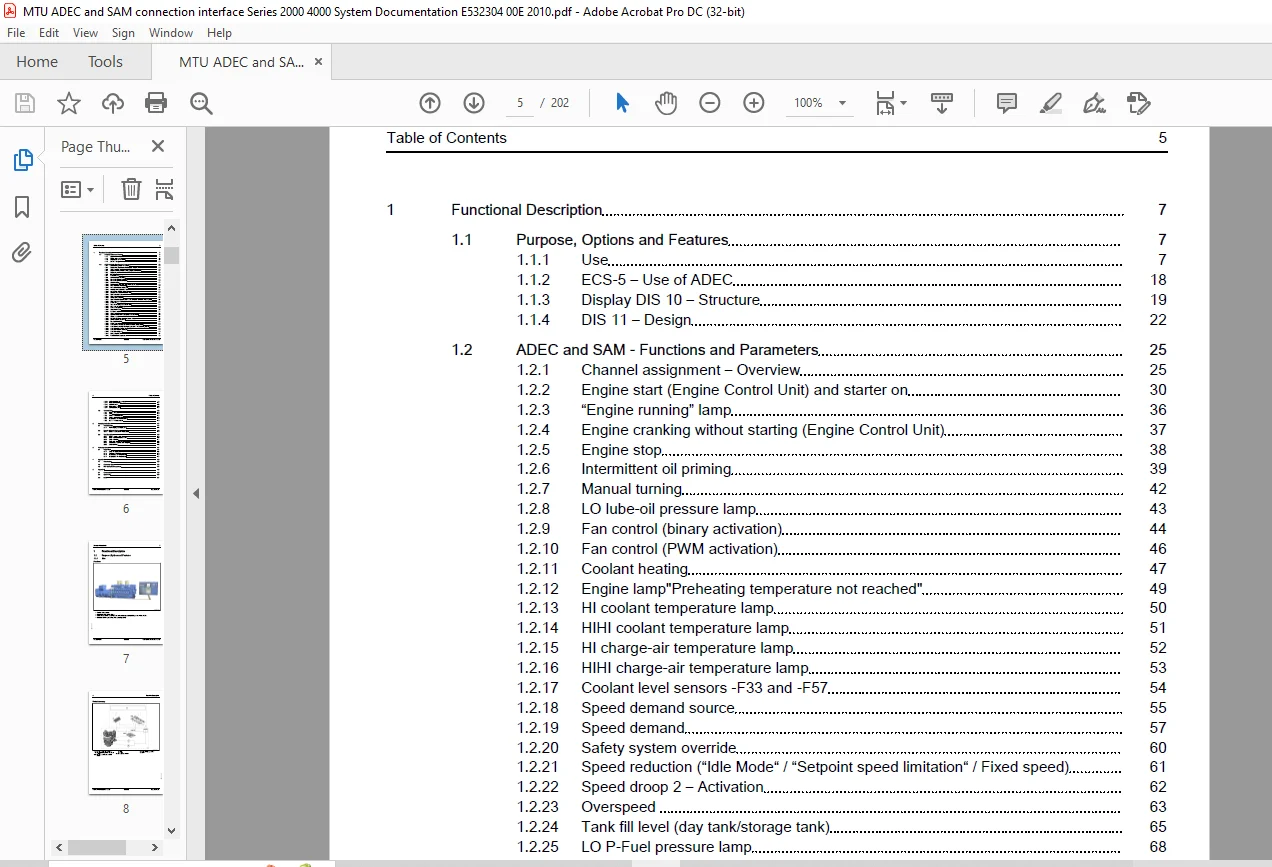
Cover Page......................................................................................  1
Commissioning Note..............................................................................  3
Table of Contents...............................................................................  5
	1 Functional Description....................................................................  7
		1.1 Purpose, Options and Features.......................................................  7
			1.1.1 Use...........................................................................  7
			1.1.2 ECS-5 – Use of ADEC........................................................... 18
			1.1.3 Display DIS 10 – Structure.................................................... 19
			1.1.4 DIS 11 – Design............................................................... 22
		1.2 ADEC and SAM - Functions and Parameters............................................. 25
			1.2.1 Channel assignment – Overview................................................. 25
			1.2.2 Engine start (Engine Control Unit) and starter on............................. 30
			1.2.3 “Engine running” lamp......................................................... 36
			1.2.4 Engine cranking without starting (Engine Control Unit)........................ 37
			1.2.5 Engine stop................................................................... 38
			1.2.6 Intermittent oil priming...................................................... 39
			1.2.7 Manual turning................................................................ 42
			1.2.8 LO lube-oil pressure lamp..................................................... 43
			1.2.9 Fan control (binary activation)............................................... 44
			1.2.10 Fan control (PWM activation)................................................. 46
			1.2.11 Coolant heating.............................................................. 47
			1.2.12 Engine lamp"Preheating temperature not reached".............................. 49
			1.2.13 HI coolant temperature lamp.................................................. 50
			1.2.14 HIHI coolant temperature lamp................................................ 51
			1.2.15 HI charge-air temperature lamp............................................... 52
			1.2.16 HIHI charge-air temperature lamp............................................. 53
			1.2.17 Coolant level sensors -F33 and -F57.......................................... 54
			1.2.18 Speed demand source.......................................................... 55
			1.2.19 Speed demand................................................................. 57
			1.2.20 Safety system override....................................................... 60
			1.2.21 Speed reduction (“Idle Mode“ / “Setpoint speed limitation“ / Fixed speed).... 61
			1.2.22 Speed droop 2 – Activation................................................... 62
			1.2.23 Overspeed.................................................................... 63
			1.2.24 Tank fill level (day tank/storage tank)...................................... 65
			1.2.25 LO P-Fuel pressure lamp...................................................... 68
			1.2.26 Water in fuel prefilter...................................................... 69
			1.2.27 Yellow alarm lamp............................................................ 70
			1.2.28 Red alarm lamp............................................................... 71
			1.2.29 Alarm reset.................................................................. 72
			1.2.30 Cylinder cutout deactivated (Engine Control Unit)............................ 73
			1.2.31 Analog outputs............................................................... 74
			1.2.32 Exhaust gas temperature A-side and B-side.................................... 79
			1.2.33  Switch 50/60Hz (reserved)................................................... 81
			1.2.34 Parameter switching.......................................................... 82
			1.2.35 Rating 1 and 2............................................................... 83
			1.2.36 Generator monitoring: DE and NDE bearing temperatures........................ 84
			1.2.37 Generator monitoring: Winding temperatures 1 to 3 and BT_OUT15............... 86
			1.2.38 Generator ready for load acceptance.......................................... 88
			1.2.39 Generator exciter boosting on................................................ 89
			1.2.40 Generator voltage on......................................................... 90
			1.2.41 Binary output test........................................................... 91
			1.2.42 Room/ambient temperature..................................................... 93
			1.2.43 SAM parameters (overview).................................................... 94
			1.2.44 Field Data Handling..........................................................107
			1.2.45 CAN interfaces...............................................................115
			1.2.46 MTU display pages............................................................118
			1.2.47 Self-diagnosis (ITS).........................................................127
		1.3 Technical Data......................................................................128
			1.3.1 Engine governor...............................................................128
			1.3.2 SAM...........................................................................130
			1.3.3 CCB 2 – Technical data........................................................134
			1.3.4 Analog display instruments....................................................135
			1.3.5 Display DIS 10 – Technical data...............................................136
			1.3.6 DIS 11 – Technical data.......................................................138
	2 Operating Instructions....................................................................141
		2.1 Troubleshooting.....................................................................141
			2.1.1 Fault displays on display SAM.................................................141
		2.2 View via Windows Web Page...........................................................166
			2.2.1 Engine Control Unit – Web feature.............................................166
		2.3 Task Description....................................................................169
			2.3.1 Engine cabling – Check........................................................169
			2.3.2 ECU – Self-test implementation................................................170
			2.3.3 SAM – Self-test...............................................................171
			2.3.4 CAN node configuration........................................................172
			2.3.5 Parameters – Setting with dialog unit.........................................173
			2.3.6 SAM minidialog................................................................175
	3 Workshop Manual...........................................................................181
		3.1 Repair Work.........................................................................181
			3.1.1 SAM – Replacement.............................................................181
			3.1.2 SAM fuse – Replacement........................................................183
			3.1.3 Display DIS 10 – Replacement..................................................184
			3.1.4 Display DIS 11 – Replacement..................................................187
	4 Appendix A................................................................................189
		4.1 Abbreviations.......................................................................189
		4.2 Conversion tables...................................................................192
		4.3 MTU Contact/Service partners........................................................197
	5 Appendix B................................................................................199
		5.1 Consumables.........................................................................199
		5.2 Spare Parts.........................................................................200
		5.3 Index...............................................................................201
PLEASE NOTE:
- This is the same manual used by the dealers to diagnose and troubleshoot your vehicle
- You will be directed to the download page as soon as the purchase is completed. The whole payment and downloading process will take anywhere between 2-5 minutes
- Need any other service / repair / parts manual, please feel free to contact [email protected] . We still have 50,000 manuals unlisted
G.P