Trusted Business
Verified & Licensed
Virus Free Files
100% Safe Downloads
Secure Payment
SSL Protected
Instant Delivery
Available Immediately
MTU Diesel Engine 12 V 2000 P12 16 V 2000 P12 Operating Instructions Manual MS150025-02E PDF DOWNLOAD
$26.95
MTU Diesel Engine 12 V 2000 P12 16 V 2000 P12 Operating Instructions Manual MS150025-02E PDF DOWNLOAD
Instant PDF Download
Available immediately
Save to Your Device
Download & keep forever
Antivirus Scanned
100% virus-free
Trusted Worldwide
175,000+ customers
Description
MTU Diesel Engine 12 V 2000 P12 16 V 2000 P12 Operating Instructions Manual MS150025-02E PDF DOWNLOAD
FILE DETAILS:
MTU Diesel Engine 12 V 2000 P12 16 V 2000 P12 Operating Instructions Manual MS150025-02E PDF DOWNLOAD
Language :English
Pages :
Downloadable : Yes
File Type : PDF
IMAGES PREVIEW OF THE MANUAL:
TABLE OF CONTENTS:
MTU Diesel Engine 12 V 2000 P12 16 V 2000 P12 Operating Instructions Manual MS150025-02E PDF DOWNLOAD
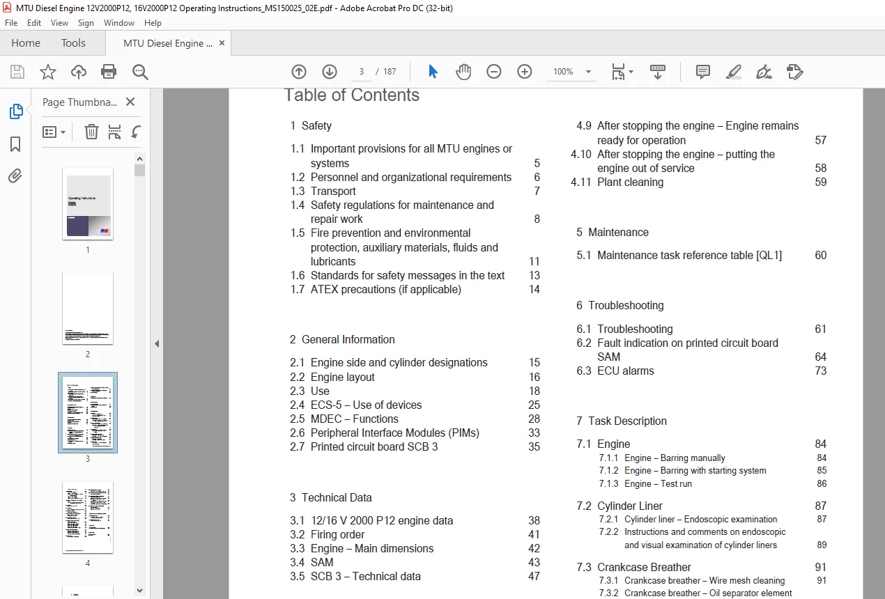
Operating Instructions.......................................................................................  1
	Table of Contents........................................................................................  3
	1 Safety.................................................................................................  5
		1.1 Important provisions for all MTU engines or systems..............................................  5
		1.2 Personnel and organizational requirements........................................................  6
		1.3 Transport........................................................................................  7
		1.4 Safety regulations for maintenance and repair work...............................................  8
		1.5 Fire prevention and environmental protection, auxiliary materials, fluids and lubricants......... 11
		1.6 Standards for safety messages in the text........................................................ 13
		1.7 ATEX precautions (if applicable)................................................................. 14
	2 General Information.................................................................................... 15
		2.1 Engine side and cylinder designations............................................................ 15
		2.2 Engine layout.................................................................................... 16
		2.3 Use.............................................................................................. 18
		2.4 ECS-5 – Use of devices........................................................................... 25
		2.5 MDEC – Functions................................................................................. 28
		2.6 Peripheral Interface Modules (PIMs).............................................................. 33
		2.7 Printed circuit board SCB 3...................................................................... 35
	3 Technical Data......................................................................................... 38
		3.1 12/16 V 2000 P12 engine data..................................................................... 38
		3.2 Firing order..................................................................................... 41
		3.3 Engine – Main dimensions......................................................................... 42
		3.4 SAM.............................................................................................. 43
		3.5 SCB 3 – Technical data........................................................................... 47
	4 Operation.............................................................................................. 48
		4.1 LOP – Controls................................................................................... 48
		4.2 Putting the engine into operation after extended out-of-service-periods (>3 months).............. 50
		4.3 Putting the engine into operation after scheduled out-of-service-period.......................... 51
		4.4 Start engine in manual mode (testing mode)....................................................... 52
		4.5 Safety system – Override......................................................................... 53
		4.6 Operational checks............................................................................... 54
		4.7 Stop engine in manual mode (testing mode)........................................................ 55
		4.8 Emergency stop................................................................................... 56
		4.9 After stopping the engine – Engine remains ready for operation................................... 57
		4.10 After stopping the engine – putting the engine out of service................................... 58
		4.11 Plant cleaning.................................................................................. 59
	5 Maintenance............................................................................................ 60
		5.1 Maintenance task reference table [QL1]........................................................... 60
	6 Troubleshooting........................................................................................ 61
		6.1 Troubleshooting.................................................................................. 61
		6.2 Fault indication on printed circuit board SAM.................................................... 64
		6.3 ECU alarms....................................................................................... 73
	7 Task Description....................................................................................... 84
		7.1 Engine........................................................................................... 84
			7.1.1 Engine – Barring manually.................................................................. 84
			7.1.2 Engine – Barring with starting system...................................................... 85
			7.1.3 Engine – Test run.......................................................................... 86
		7.2 Cylinder Liner................................................................................... 87
			7.2.1 Cylinder liner – Endoscopic examination.................................................... 87
			7.2.2 Instructions and comments on endoscopic and visual examination of cylinder liners.......... 89
		7.3 Crankcase Breather............................................................................... 91
			7.3.1 Crankcase breather – Wire mesh cleaning.................................................... 91
			7.3.2 Crankcase breather – Oil separator element replacement, diaphragm check and replacement.... 93
		7.4 Valve Drive...................................................................................... 95
			7.4.1 Valve clearance – Check and adjustment..................................................... 95
			7.4.2 Cylinder head cover – Removal and installation............................................. 97
		7.5 Injection Pump / HP Pump......................................................................... 98
			7.5.1 Injection pump – Replacement............................................................... 98
			7.5.2 Injection pump – Removal and installation.................................................. 99
		7.6 Injection Valve / Injector.......................................................................102
			7.6.1 Injector – Replacement.....................................................................102
			7.6.2 Injector – Removal and installation........................................................103
		7.7 Fuel System......................................................................................106
			7.7.1 Fuel pressure relief valve – Replacement...................................................106
			7.7.2 Fuel – Draining............................................................................108
			7.7.3 Fuel system – Venting......................................................................109
		7.8 Fuel Filter......................................................................................110
			7.8.1 Fuel filter – Replacement..................................................................110
			7.8.2 Fuel prefilter cleaning....................................................................112
			7.8.3 Fuel prefilter – Differential pressure gauge check and adjustment..........................113
			7.8.4 Fuel prefilter – Draining..................................................................114
			7.8.5 Fuel prefilter – Flushing..................................................................115
			7.8.6 Fuel prefilter – Filter element replacement................................................117
		7.9 Charge-Air Cooling General, Left-Hand Side.......................................................119
			7.9.1 Intercooler – Checking condensate drains for coolant discharge  and obstructions...........119
		7.10 Air Filter......................................................................................120
			7.10.1 Air filter – Replacement..................................................................120
		7.11 Air Intake......................................................................................121
			7.11.1 Service indicator – Signal ring position check............................................121
		7.12 Starting Equipment..............................................................................122
			7.12.1 Starter – Condition check.................................................................122
		7.13 Lube Oil System, Lube Oil Circuit...............................................................123
			7.13.1 Engine oil – Level check..................................................................123
			7.13.2 Engine oil – Change.......................................................................124
		7.14 Oil Filtration / Cooling........................................................................125
			7.14.1 Engine oil filter – Replacement...........................................................125
		7.15 Coolant Circuit, General, High-Temperature Circuit..............................................127
			7.15.1 Drain and venting points..................................................................127
			7.15.2 Engine coolant – Level check..............................................................131
			7.15.3 Engine coolant – Change...................................................................132
			7.15.4 Engine coolant – Draining.................................................................133
			7.15.5 Engine coolant – Filling..................................................................134
			7.15.6 Coolant pump – Relief bore check..........................................................136
		7.16 Low-Temperature Circuit.........................................................................137
			7.16.1 Charge-air coolant – Filling..............................................................137
			7.16.2 Charge-air coolant – Draining.............................................................139
			7.16.3 Charge-air coolant – Change...............................................................140
			7.16.4 Charge-air coolant – Level check..........................................................141
		7.17 Belt Drive......................................................................................142
			7.17.1 Drive belt – Condition check..............................................................142
		7.18 Engine Mounting / Support.......................................................................143
			7.18.1 Engine mounts – Resilient elements check..................................................143
		7.19 Wiring (General) for Engine/Gearbox/Unit........................................................144
			7.19.1 Engine wiring – Check.....................................................................144
		7.20 Accessories for (Electronic) Engine Governor / Control System...................................145
			7.20.1 Engine governor and connectors – Cleaning.................................................145
			7.20.2 Engine monitoring unit and connectors – Cleaning..........................................146
			7.20.3 Checking engine control unit plug connections.............................................147
			7.20.4 Engine monitoring unit – Plug connection check............................................148
			7.20.5 Engine control unit – Removal and installation............................................149
		7.21 Emergency Instrumentation (Local Operating Panel)...............................................151
			7.21.1 LOP – Visual inspection...................................................................151
			7.21.2 LOP – Test procedures.....................................................................154
	8 Engine Governor Assignment and Circuitry...............................................................156
		8.1 Engine Governor..................................................................................156
			8.1.1 Engine governor channel circuitry..........................................................156
			8.1.2 MDEC governor assignment...................................................................165
		8.2 Connector Assignment.............................................................................167
			8.2.1 Connector pin assignment...................................................................167
	9 Appendix A.............................................................................................176
		9.1 Abbreviations....................................................................................176
		9.2 MTU contact persons/service partners.............................................................179
	10 Appendix B............................................................................................180
		10.1 Special Tools...................................................................................180
		10.2 Index...........................................................................................186
Contact us: [email protected]
https://vimeo.com/858566529?share=copy
DESCRIPTION:
MTU Diesel Engine 12 V 2000 P12 16 V 2000 P12 Operating Instructions Manual MS150025-02E PDF DOWNLOAD
1 Safety
1.1 Important provisions for all MTU engines or systems
Nameplate:
- Engine identification is provided by the engine serial number on the nameplate.
- The nameplate is located on the engine.
General information:
- This engine or plant may present a risk of injury or damage in the following cases:
- Incorrect use
- Operation, maintenance, and repair by unqualified personnel
- Modifications or conversions
- Noncompliance with the safety instructions
Correct use:
- The engine or plant is intended solely for use in accordance with contractual agreements and the purpose envisaged for it on delivery.
- This means that the equipment must be operated:
- Within the permissible operating parameters in accordance with the (→ engine data)
- With fluids and lubricants approved by MTU in accordance with the (→ MTU Fluids and Lubricants Specifications)
- With spare parts approved by MTU in accordance with the associated (→ Spare Parts Catalog)
- In the original as-delivered configuration or in a configuration approved by MTU in writing (engine and engine control/parameters)
- In compliance with all safety instructions and in adherence to all warning notices in these Operating Instructions
- In compliance with the maintenance and repair instructions contained in these Operating Instructions, in particular with regard to the specified tightening torques
- Appointing only qualified personnel to carry out work related to initial startup, operation, maintenance, and repair
- Contracting only workshops authorized by MTU to carry out repair and overhaul
- Any other use is considered improper use and increases the risk of personnel injury or material damage in engine/plant operation. MTU will accept no liability for such damage.
Modifications or conversions:
- Unauthorized modifications to the engine or plant represent a safety risk.
- MTU will accept no liability or warranty claims for any damage caused by unauthorized modifications or conversions.
Spare parts:
- Only genuine MTU spare parts must be used to replace components or assemblies.
- MTU will accept no liability or warranty claims for any damage caused by the use of other spare parts
PLEASE NOTE:
- This is the same manual used by the dealers to diagnose and troubleshoot your vehicle
- You will be directed to the download page as soon as the purchase is completed. The whole payment and downloading process will take anywhere between 2-5 minutes
- Need any other service / repair / parts manual, please feel free to contact [email protected] . We still have 50,000 manuals unlisted
S.S