Trusted Business
Verified & Licensed
Virus Free Files
100% Safe Downloads
Secure Payment
SSL Protected
Instant Delivery
Available Immediately
MTU Diesel Engine 12 V 4000 R41 16 V 4000 R41 Workshop Manual M020124-02E PDF DOWNLOAD
$35.95
MTU Diesel Engine 12 V 4000 R41 16 V 4000 R41 Workshop Manual M0920124-02E PDF DOWNLOAD
Instant PDF Download
Available immediately
Save to Your Device
Download & keep forever
Antivirus Scanned
100% virus-free
Trusted Worldwide
175,000+ customers
Description
MTU Diesel Engine 12 V 4000 R41 16 V 4000 R41 Workshop Manual M020124-02E PDF DOWNLOAD
FILE DETAILS:
MTU Diesel Engine 12 V 4000 R41 16 V 4000 R41 Workshop Manual M020124-02E PDF DOWNLOAD
Language :English
Pages :1846
Downloadable : Yes
File Type : PDF
IMAGES PREVIEW OF THE MANUAL:
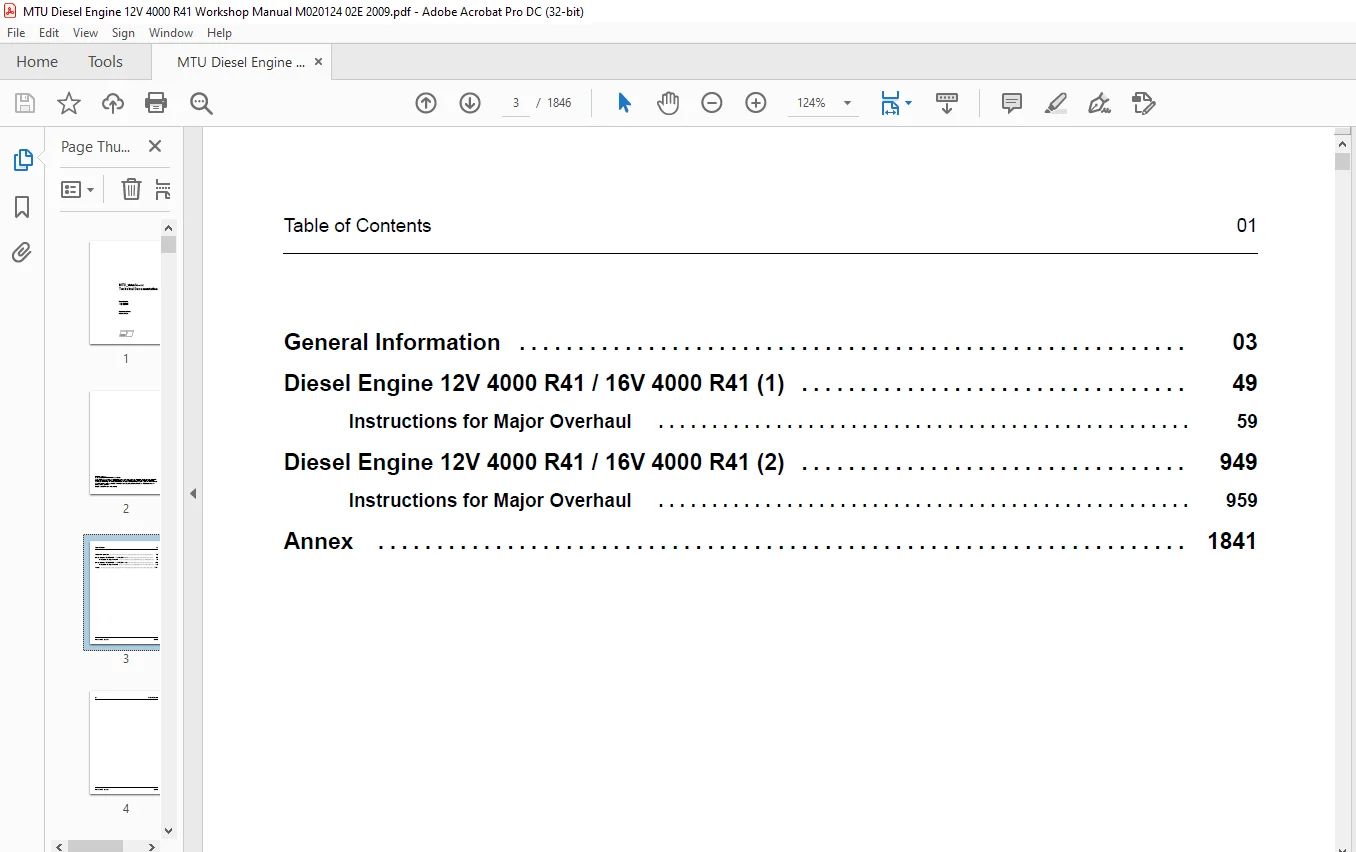
TABLE OF CONTENTS:
MTU Diesel Engine 12 V 4000 R41 16 V 4000 R41 Workshop Manual M020124-02E PDF DOWNLOAD
Title................................................................................... 1 Table of Contents - Overview............................................................ 3 General Information - Table of Contents................................................. 5 1 Important Notes................................................................... 7 1.1 Prerequisites for maintenance work and general assembly inst................ 7 Prerequisites for maintenance work.......................................... 7 General assembly instructions............................................... 7 1.2 Reman assemblies............................................................ 9 Reman assemblies............................................................ 9 2 General Conditions................................................................ 11 2.1 General Instructions........................................................ 11 General..................................................................... 11 Correct use................................................................. 11 Modifications or conversions................................................ 11 Spare parts................................................................. 11 Reworking components........................................................ 11 2.2 Personnel and organizational requirements .................................. 12 Personnel requirements...................................................... 12 Organizational measures..................................................... 12 Working clothes and protective equipment.................................... 12 2.3 Safety precautions when working on the engine............................... 13 Safety precautions when putting the equipment into operation................ 13 Safety requirements for operators........................................... 13 Engine operation............................................................ 13 Maintenance and repair...................................................... 13 Welding work................................................................ 14 Hydraulic installation and removal.......................................... 14 Working on electrical/electronic assemblies................................. 15 Working with laser equipment................................................ 15 Operation of electrical equipment........................................... 15 2.4 Auxiliary materials, fire prevention and environmental prote................ 16 Fire prevention............................................................. 16 Noise....................................................................... 16 Environmental protection.................................................... 16 Auxiliary materials......................................................... 16 Lead........................................................................ 16 Acids and alkaline solutions................................................ 16 Painting.................................................................... 16 Liquid nitrogen............................................................. 16 Compressed air.............................................................. 17 Used oil.................................................................... 17 2.5 Standards for warning notices in the publication............................ 18 2.6 General information regarding the Tolerances and Wear Limits................ 19 2.7 Engine side and cylinder designations....................................... 20 2.8 Tightening specifications for screws, nuts and bolts........................ 21 Crankcase................................................................... 21 Crank drive................................................................. 22 Cylinder head............................................................... 23 Valve gear.................................................................. 24 Fuel system – high pressure................................................. 24 Exhaust turbocharger........................................................ 25 Exhaust pipework............................................................ 25 Charge air cooling.......................................................... 25 Starting equipment.......................................................... 25 Lube-oil system............................................................. 26 Battery-charging generator.................................................. 26 Mounting / support.......................................................... 26 PTO systems, driving end and free end (coupling)............................ 27 Monitoring, control and regulation devices.................................. 28 Tightening specification for setscrew and stud connections as pe............ 28 Tightening torques for stress bolt connections as per works stan............ 30 Tightening torques for plugs as per works standard MTN 5183-1 .............. 31 Tightening torques for plugs as per DIN 7604C (with long screwed............ 34 Tightening torques for banjo screws as per works standard MTN 51............ 34 Tightening torques for banjo screws made of steel........................... 35 Tightening torques for banjo screws made of copperaluminum allo............ 36 Tightening torques for male connector as per works standard MTN ............ 36 Tightening torques for union nut on screwed plug ISO 6149-3................. 37 2.9 Settings.................................................................... 38 Firing order for Series 4000 engines ....................................... 38 Direction of rotation, viewed towards driving end........................... 38 Valve clearance, engine cold (20 °C)........................................ 38 Valve timing with valve clearance adjusted.................................. 39 Cam and valve lift for camshaft adjustment.................................. 39 2.10 Conversion tables.......................................................... 40 Length...................................................................... 40 Area........................................................................ 40 Volume...................................................................... 41 Speed....................................................................... 41 Mass........................................................................ 42 Force....................................................................... 42 Density..................................................................... 42 Torque...................................................................... 43 Pressure.................................................................... 43 Mass moment, 2nd grade...................................................... 43 Energy...................................................................... 44 Power....................................................................... 44 Temperature................................................................. 45 Fuel consumption............................................................ 45 2.11 Repairing threaded bores with threaded inserts (Heli-Coil)................. 46 2.12 Abbreviations.............................................................. 48 Diesel Engine 12V 4000 R41 / 16V 4000 R41 (1) - Table of Contents....................... 51 Instructions for Major Overhaul..................................................... 61 3 Maintenance Schedule 12V 4000 R41 / 16V 4000 R41.............................. 63 3.1 Maintenance............................................................. 63 3.1.1 Preface........................................................... 63 MTU maintenance concept............................................. 63 Notes on maintenance................................................ 63 Out-of-service periods.............................................. 63 Application group................................................... 63 Load profile........................................................ 64 3.1.2 Maintenance schedule matrix....................................... 65 0 - 21,000 Operating hours.......................................... 65 22,000 - 30,000 Operating hours..................................... 66 3.1.3 Maintenance tasks................................................. 67 4 Task Schedules................................................................ 69 4.1 Engine – Checking condition before a major overhaul..................... 69 4.2 Engine – Removal........................................................ 71 4.3 Engine – Disassembly.................................................... 72 4.4 Engine – Assembly....................................................... 75 4.5 Engine – Installation................................................... 77 4.6 Engine – Run-in procedure............................................... 78 Running in engine after replacing parts................................. 78 Adjust engine operational data.......................................... 78 4.7 Initial engine operation................................................ 81 4.8 Tightening specifications for screws, nuts and bolts.................... 82 Crankcase............................................................... 82 Crank drive............................................................. 83 Cylinder head........................................................... 84 Valve gear.............................................................. 85 Fuel system – high pressure............................................. 85 Exhaust turbocharger.................................................... 86 Exhaust pipework........................................................ 86 Charge air cooling...................................................... 86 Starting equipment...................................................... 86 Lube-oil system......................................................... 87 Battery-charging generator.............................................. 87 Mounting / support...................................................... 87 PTO systems, driving end and free end (coupling)........................ 88 Monitoring, control and regulation devices.............................. 89 Tightening specification for setscrew and stud connections as pe........ 89 Tightening torques for stress bolt connections as per works stan........ 91 Tightening torques for plugs as per works standard MTN 5183-1 .......... 92 Tightening torques for plugs as per DIN 7604C (with long screwed........ 95 Tightening torques for banjo screws as per works standard MTN 51........ 95 Tightening torques for banjo screws made of steel....................... 96 Tightening torques for banjo screws made of copperaluminum allo........ 97 Tightening torques for male connector as per works standard MTN ........ 97 Tightening torques for union nut on screwed plug ISO 6149-3............. 98 5 Task Descriptions............................................................. 99 5.1 Crankcase and Externally Mounted Components............................. 99 5.1.1 Engine layout..................................................... 99 Illustration applies analogously to 8/12/16 V 4000 G, C and R....... 99 5.1.2 Crankcase and attachments – Overview.............................. 100 Overview of crankcase and attachments............................... 100 5.1.3 Crankcase – Overview ............................................. 101 Crankcase with cover................................................ 101 Crankcase........................................................... 102 Oil filler neck with oil dipstick................................... 103 5.1.4 Crankcase – Disassembly........................................... 104 5.1.5 Crankcase – Cleaning.............................................. 107 5.1.6 Crankcase – Checking upper and lower cylinder liner fit........... 109 5.1.7 Crankcase – Check................................................. 112 5.1.8 Crankcase – Tolerances............................................ 118 Crankcase bore for crankshaft....................................... 118 Crankcase bore for camshaft......................................... 119 Top deck and cylinder liner mating face............................. 120 Crankcase bore for cylinder liner................................... 121 Main bearing cap.................................................... 122 Main bearing bore................................................... 123 Crankcase crankshaft bore coaxiality................................ 124 Crankcase camshaft bore coaxiality.................................. 125 5.1.9 Crankcase – Assembly.............................................. 126 5.1.10 Cylinder liner – Overview........................................ 134 Overview of cylinder liner with scraper ring........................ 134 Cylinder liner with scraper ring in crankcase....................... 135 5.1.11 Cylinder liner – Removal......................................... 136 5.1.12 Cylinder liner – Cleaning........................................ 138 5.1.13 Cylinder liner – Check........................................... 139 5.1.14 Cylinder liner – Tolerances...................................... 141 Cylinder liner...................................................... 143 Reconditioning instructions:........................................ 143 5.1.15 Cylinder liner – Installation.................................... 144 5.1.16 Oil pan – Overview............................................... 147 View from free end.................................................. 148 5.1.17 Oil pan – Removal................................................ 149 5.1.18 Oil pan – Cleaning............................................... 150 5.1.19 Oil pan – Check.................................................. 151 5.1.20 Oil pan – Installation........................................... 152 5.1.21 Tightening sequence for oil pan made of nodular cast iron........ 155 Threaded connections for oil pan made of nodular cast iron (GGG).... 155 5.1.22 Engine lifting equipment - Overview.............................. 156 Overview............................................................ 156 Engine lifting equipment............................................ 157 5.1.23 Engine lifting equipment – Removal............................... 158 5.1.24 Engine lifting equipment – Cleaning.............................. 159 5.1.25 Engine lifting equipment – Check................................. 160 5.1.26 Engine lifting equipment – Installation.......................... 161 5.1.27 End housing, driving end – Overview.............................. 162 End housing with attachments........................................ 162 Configuration of guide bush for end housing installation and rem.... 163 5.1.28 End housing, driving end – Removal............................... 164 5.1.29 End housing, driving end – Disassembly........................... 165 5.1.30 End housing, driving end – Cleaning.............................. 166 5.1.31 End housing, driving end – Check................................. 167 5.1.32 End housing KS – Tolerances...................................... 168 5.1.33 End housing, driving end – Assembly.............................. 169 5.1.34 End housing, driving end – Installation.......................... 171 5.1.35 Crankcase ventilation – Overview................................. 173 Crankcase ventilation, driving end, 16V............................. 173 Crankcase ventilation, driving end, 12V............................. 174 Crankcase ventilation, free end, 12V, 16V........................... 175 5.1.36 Crankcase ventilation – Removal.................................. 176 5.1.37 Crankcase ventilation – Cleaning................................. 177 5.1.38 Crankcase ventilation – Check.................................... 178 5.1.39 Oil separator – Disassembly...................................... 179 5.1.40 Oil separator – Check............................................ 181 5.1.41 Oil separator – Assembly......................................... 182 5.1.42 Crankcase ventilation – Installation............................. 185 5.2 Gear Train.............................................................. 186 5.2.1 Gearcase, free end – Overview..................................... 186 Arrangement of alignment tool for equipment carrier and equipmen.... 187 5.2.2 Gearcase, free end – Removal...................................... 188 5.2.3 Gearcase, free end – Disassembly.................................. 190 5.2.4 Equipment carrier free end – Cleaning............................. 191 5.2.5 Gearcase, free end – Check........................................ 192 5.2.6 Gearcase, free end – Tolerances................................... 193 5.2.7 Gearcase, free end – Assembly..................................... 194 5.2.8 Gearcase, free end – Installation................................. 197 5.2.9 Gear train, free end – Overview................................... 201 5.2.10 Gear train, free end – Removal................................... 203 5.2.11 Gear train, free end – Cleaning.................................. 204 5.2.12 Gear train, free end – Check..................................... 205 5.2.13 Gear train, free end – Tolerances................................ 207 5.2.14 Gear train, free end – Installation.............................. 209 5.2.15 Bearing bushing of idler gear – Removal and installatio.......... 212 5.3 Crank Drive............................................................. 214 5.3.1 Running gear – Overview .......................................... 214 Running gear........................................................ 214 5.3.2 Crankshaft – Overview............................................. 215 Crankshaft detail................................................... 215 Crankshaft.......................................................... 216 Crankshaft with bearings............................................ 217 5.3.3 Crankshaft – Removal.............................................. 218 5.3.4 Crankshaft – Disassembly.......................................... 222 5.3.5 Crankshaft - Cleaning............................................. 223 5.3.6 Crankshaft – Check................................................ 224 5.3.7 Crankshaft – Tolerances........................................... 228 Crankshaft bearing.................................................. 228 Conrod bearings..................................................... 230 Crankshaft bearing, alignment bearing – expanding dimension......... 231 Crankshaft bearing – expanding dimension............................ 232 Crankshaft axial play............................................... 233 Crankshaft bearing shells........................................... 234 Crankshaft gear, free end........................................... 235 Main bearing journal concentricity.................................. 236 5.3.8 Crankshaft - Assembly............................................. 238 5.3.9 Crankshaft – Balancing............................................ 240 5.3.10 Crankshaft bearing shells - Check................................ 242 Crankshaft bearing shells - Check................................... 242 Main bearing shells (grooved bearing), upper half................... 242 Assessment.......................................................... 242 Main bearing shell (sputtered bearing), lower half.................. 243 Assessment.......................................................... 243 Damage to bearing................................................... 243 5.3.11 Crankshaft bearing bore – Check.................................. 244 5.3.12 Crankshaft – Installation........................................ 247 5.3.13 PTO flange, driving end, flywheel – Overview..................... 255 Layout for installation/removal jig for flywheel.................... 256 5.3.14 PTO flange, driving end, flywheel – Removal...................... 257 5.3.15 Radial-lip shaft seal, driving end – Removal..................... 261 5.3.16 Flywheel on PTO flange, driving end – Cleaning................... 262 5.3.17 Flywheel on PTO flange, driving end – Check...................... 263 5.3.18 Radial-lip shaft seal, driving end – Installation................ 264 5.3.19 PTO flange, driving end, flywheel – Installation................. 265 5.3.20 Crankshaft PTO, Free end – Overview.............................. 269 Arrangement of the drive flange installation/removal tool .......... 270 5.3.21 Vibration damper on PTO, free end – Removal...................... 271 5.3.22 Vibration damper on PTO, free end – Disassembly.................. 274 Vibration damper – Disassembly...................................... 274 5.3.23 Vibration damper on PTO, free end – Cleaning..................... 275 5.3.24 Vibration damper on PTO, free end – Check........................ 276 5.3.25 Vibration damper on PTO, free end – Tolerances................... 277 5.3.26 Vibration damper on PTO, free end – Installation................. 278 5.3.27 Piston and conrod – Overview..................................... 282 Piston and conrod................................................... 282 Piston details ..................................................... 283 5.3.28 Piston and conrod – Removal...................................... 284 5.3.29 Piston and conrod – Disassembly.................................. 287 5.3.30 Piston – Cleaning................................................ 289 5.3.31 Piston – Check................................................... 290 5.3.32 Piston – Tolerances.............................................. 293 Piston bearing...................................................... 293 Piston rings........................................................ 294 Piston clearance in cylinder liner.................................. 296 Piston crown mounting............................................... 298 5.3.33 Conrod – Disassembly............................................. 299 5.3.34 Conrod – Cleaning................................................ 300 5.3.35 Conrod – Check................................................... 301 5.3.36 Conrod – Tolerances.............................................. 308 Conrod bearings..................................................... 308 Conrod screw length................................................. 309 Conrod bore parallelism............................................. 310 Small conrod bore................................................... 311 5.3.37 Conrod – Assembly................................................ 312 5.3.38 Piston – Assembly................................................ 314 5.3.39 Piston and conrod – Installation................................. 317 5.4 Cylinder Head........................................................... 324 5.4.1 Cylinder head and attachments – Overview.......................... 324 Cylinder head and attachments – Overview............................ 324 5.4.2 Valve-seat turning machine for cylinder head...................... 327 Working principle of valve-seat turning machine..................... 327 Installing the solid pilot.......................................... 328 Mounting the supporting spider...................................... 328 Inserting the pilot into the valve guide............................ 328 Locking the pilot................................................... 328 Setting up valve turning machine.................................... 329 Mounting the cutter................................................. 329 Placing the valve-turning machine on the pilot...................... 329 Aligning the cutting edge with the valve-seat center................ 329 Connecting the machine to power supply.............................. 329 Valve seat turning.................................................. 330 Positioning the cutter at the inner valve-seat edge................. 330 Setting cutting depth............................................... 330 Lubricating the valve seat.......................................... 330 Valve seat turning.................................................. 330 Repeating the cutting pass.......................................... 330 Replacing the adapter head.......................................... 331 Removing the adapter head........................................... 331 Mounting the adapter head........................................... 331 5.4.3 Cylinder head – Removal........................................... 332 5.4.4 Cylinder head – Disassembly....................................... 335 5.4.5 Cylinder head – Cleaning.......................................... 337 5.4.6 Cylinder head – Check............................................. 338 5.4.7 Cylinder head – Tolerances........................................ 341 Cylinder head tolerances for heads with valve seat inserts and e.... 341 Inlet and exhaust valve guides...................................... 341 Valve clearance..................................................... 342 Inlet and exhaust valve seat ring................................... 343 Inlet and exhaust valve-seat insert................................. 344 Inlet valve elliptical chamfer...................................... 345 Exhaust valve....................................................... 346 Inlet valve......................................................... 347 Valve springs, outer................................................ 348 Valve springs, inner................................................ 349 Cylinder head – mating surface – protective sleeve.................. 351 Cylinder head screws................................................ 352 5.4.8 Cylinder head – Repair............................................ 353 5.4.9 Cylinder head – Plug repair....................................... 359 5.4.10 Cylinder head – Assembly......................................... 361 5.4.11 Cylinder head – Installation..................................... 366 5.5 Valve Gear.............................................................. 370 5.5.1 Valve gear – Overview............................................. 370 Valve gear – Overview............................................... 370 5.5.2 Camshaft overview................................................. 371 Overview of camshaft................................................ 371 5.5.3 Camshaft – Removal................................................ 372 5.5.4 Camshaft – Cleaning............................................... 374 5.5.5 Camshaft running surfaces and swing followers – Visual i.......... 375 5.5.6 Camshaft – Check.................................................. 376 5.5.7 Camshaft – Tolerances............................................. 379 Concentricity of bearings........................................... 379 Axial clearance..................................................... 380 5.5.8 Camshaft – Installation........................................... 381 5.5.9 Camshaft drive – Overview......................................... 388 Camshaft drive – Overview........................................... 388 5.5.10 Camshaft drive – Removal......................................... 389 5.5.11 Camshaft drive – Cleaning........................................ 391 5.5.12 Camshaft drive – Check........................................... 392 5.5.13 Camshaft drive – Installation.................................... 393 5.5.14 Camshaft thrust bearing – Overview............................... 394 Overview of camshaft thrust bearing................................. 394 5.5.15 Camshaft thrust bearing – Cleaning............................... 395 5.5.16 Camshaft thrust bearing – Replacement............................ 396 5.5.17 Camshaft thrust bearing – Check.................................. 397 5.5.18 Valve drive – Overview........................................... 398 Rocker arm, swing follower assembly................................. 398 Rocker shaft support................................................ 399 Swing follower...................................................... 400 Valve bridge........................................................ 401 5.5.19 Valve drive – Removal............................................ 402 5.5.20 Valve drive - Disassembly........................................ 403 5.5.21 Valve drive – Cleaning........................................... 406 5.5.22 Valve drive – Check.............................................. 407 5.5.23 Valve drive – Tolerances......................................... 410 Rocker shaft support, inlet and exhaust............................. 410 Swing follower support, inlet and exhaust........................... 411 5.5.24 Valve drive – Assembly........................................... 412 5.5.25 Valve drive – Installation....................................... 416 5.5.26 Cylinder head cover – Overview................................... 420 5.5.27 Cylinder head cover – Removal.................................... 421 5.5.28 Cylinder head cover – Cleaning................................... 422 5.5.29 Cylinder head cover – Check...................................... 423 5.5.30 Cylinder head cover – Installation............................... 424 5.6 High Pressure Fuel System............................................... 425 5.6.1 HP fuel system – Overview......................................... 425 5.6.2 HP pump – Overview................................................ 426 Front view of HP pump............................................... 427 5.6.3 HP pump – Removal................................................. 428 5.6.4 High-pressure pump – Disassembly.................................. 430 5.6.5 High-pressure pump – Check........................................ 431 5.6.6 HP pump – Installation............................................ 432 5.6.7 H.P. fuel pump – Control block replacement........................ 434 5.6.8 Injector – Overview............................................... 436 Injector – Overview................................................. 436 5.6.9 Injector – Removal................................................ 437 5.6.10 Fuel injector disassembly........................................ 440 5.6.11 Injector – Cleaning.............................................. 441 5.6.12 Injector – Check................................................. 442 5.6.13 Injector – Installation.......................................... 443 5.6.14 High-pressure line – Overview.................................... 446 HP line from HP accumulator to injector............................. 446 HP line from HP pump to HP accumulator.............................. 447 HP accumulator and add-on components................................ 448 HP accumulator, left engine side.................................... 449 HP accumulator, right engine side................................... 449 5.6.15 HP fuel line – Removal........................................... 451 5.6.16 HP fuel line – Disassembly....................................... 455 5.6.17 HP fuel line – Cleaning.......................................... 456 5.6.18 H.P. fuel line – Check........................................... 457 5.6.19 HP fuel line – Assembly.......................................... 458 5.6.20 HP fuel line – Installation...................................... 461 5.6.21 H.P. fuel system – Leak check.................................... 466 5.7 Low Pressure Fuel System................................................ 467 5.7.1 Fuel system – Overview............................................ 467 Fuel system......................................................... 467 5.7.2 Fuel delivery pump – Overview..................................... 468 Fuel delivery pump – Overview....................................... 468 5.7.3 Fuel delivery pump – Removal...................................... 469 5.7.4 Fuel delivery pump – Disassembly.................................. 470 Disassembling fuel delivery pump.................................... 470 5.7.5 Fuel delivery pump – Cleaning..................................... 471 5.7.6 Fuel delivery pump – Check........................................ 472 5.7.7 Fuel delivery pump – Installation................................. 473 5.7.8 Fuel delivery pump – Overview..................................... 474 5.7.9 Fuel delivery pump – Removal...................................... 475 5.7.10 Fuel delivery pump – Cleaning.................................... 476 5.7.11 Fuel delivery pump – Installation................................ 477 5.7.12 Fuel pipework from fuel delivery pump to fuel filter – .......... 478 5.7.13 Fuel lines from fuel delivery pump to fuel filter – Rem.......... 479 5.7.14 Fuel lines from pump to filter – Cleaning........................ 480 5.7.15 Fuel lines from fuel delivery pump to fuel filter – Che.......... 481 5.7.16 Fuel lines from fuel delivery pump to fuel filter – Ins.......... 482 5.7.17 Fuel duplex filter – Overview.................................... 483 5.7.18 Fuel duplex filter – Removal..................................... 484 5.7.19 Fuel duplex filter – Disassembly................................. 485 5.7.20 Fuel filter – Cleaning........................................... 486 5.7.21 Fuel filter – Check.............................................. 487 5.7.22 Fuel duplex filter – Assembly.................................... 488 5.7.23 Fuel duplex filter – Installation................................ 489 5.7.24 Fuel pipework from fuel filter to HP pump – Overview ............ 490 Fuel line........................................................... 490 5.7.25 Fuel pipework from fuel filter to HP pump – Removal ............. 491 5.7.26 Fuel pipework from fuel filter to high-pressure pump – .......... 492 5.7.27 Fuel pipework from fuel filter to high-pressure pump – .......... 493 5.7.28 Fuel pipework from fuel filter to HP pump – Installatio.......... 494 5.7.29 Leak-off fuel pipework – Overview................................ 495 Fuel return lines................................................... 495 5.7.30 Leak-off fuel line – Removal..................................... 497 5.7.31 Leak-off fuel pipework – Cleaning................................ 498 5.7.32 Leak-off fuel pipework – Check................................... 499 5.7.33 Leak-off fuel line – Installation................................ 500 5.8 Exhaust Turbocharger.................................................... 501 5.8.1 Exhaust turbochargers – Overview.................................. 501 Exhaust turbochargers – Overview.................................... 501 5.8.2 Exhaust turbocharger – Removal.................................... 502 5.8.3 Exhaust turbocharger – Disassembly................................ 503 5.8.4 Exhaust turbocharger – Cleaning................................... 507 5.8.5 Exhaust turbocharger – Check...................................... 508 5.8.6 Exhaust turbocharger – Tolerances................................. 512 Admissible contour clearance for K36................................ 512 Admissible contour clearance for K37................................ 513 5.8.7 Exhaust turbocharger – Assembly................................... 514 5.8.8 Exhaust turbocharger – Installation............................... 520 5.9 Charge-Air Cooling...................................................... 521 5.9.1 Intercooler – Overview............................................ 521 Intercooler......................................................... 521 Intercooler and attachments......................................... 522 5.9.2 Intercooler – Removal............................................. 523 5.9.3 Intercooler – Cleaning............................................ 524 Air-side cleaning................................................... 524 Water-side cleaning................................................. 524 Intercooler – Flushing.............................................. 524 Intercooler – Drying and preservation............................... 524 5.9.4 Intercooler – Check............................................... 525 5.9.5 Intercooler – Installation........................................ 527 5.10 Air Intake/Air Supply.................................................. 528 5.10.1 Air intake / air supply – Overview............................... 528 5.10.2 Intake housing – Overview........................................ 529 Air Intake.......................................................... 529 Air Intake.......................................................... 530 5.10.3 Intake housing – Removal......................................... 531 5.10.4 Intake housing – Cleaning........................................ 532 5.10.5 Intake housing – Check........................................... 533 5.10.6 Intake housing – Installation.................................... 534 5.10.7 Intake air system to cylinders, left – Overview.................. 535 5.10.8 Air supply system to cylinders, left-hand side – Remova.......... 536 5.10.9 Air supply system to cylinders, left – Cleaning.................. 537 5.10.10 Air supply to cylinders, left side – Check...................... 538 5.10.11 Air supply system to cylinders, left-hand side – Insta.......... 539 5.10.12 Air supply system to cylinders, right – Overview................ 540 5.10.13 Air supply system to cylinders, right-hand side – Remo.......... 541 5.10.14 Air supply system to cylinders, right – Cleaning................ 542 5.10.15 Air supply to cylinders, RHS – Check............................ 543 5.10.16 Air supply system to cylinders, right-hand side – Inst.......... 544 5.10.17 Air pipework from turbocharger to intercooler – Overvi.......... 545 Air pipework 12V.................................................... 545 Air pipework 16V.................................................... 547 Intercooler elbow................................................... 548 5.10.18 Air pipework from exhaust turbocharger to intercooler .......... 549 5.10.19 Air supply from turbocharger to intercooler – Cleaning.......... 550 5.10.20 Air ducts from turbocharger to intercooler – Check.............. 551 5.10.21 Air pipework from turbocharger to intercooler – Instal.......... 552 5.11 Exhaust System......................................................... 553 5.11.1 Exhaust system – Overview........................................ 553 Exhaust system...................................................... 553 5.11.2 Exhaust pipework after cylinder head – Overview.................. 554 Exhaust pipework 16V (also applicable to 8V / 12V).................. 554 5.11.3 Exhaust pipework after cylinder head – Removal................... 555 5.11.4 Exhaust pipework after cylinder head – Clean..................... 557 5.11.5 Exhaust pipework after cylinder head – Check..................... 558 5.11.6 Exhaust pipework after cylinder head – Installation.............. 559 5.11.7 Exhaust pipework after exhaust turbocharger – Overview........... 562 Exhaust pipework.................................................... 562 5.11.8 Exhaust pipework after exhaust turbocharger – Removal............ 564 5.11.9 Exhaust pipework after turbocharger – Cleaning................... 565 5.11.10 Exhaust pipework after exhaust turbocharger – Check............. 566 5.11.11 Exhaust pipework after exhaust turbocharger – Installa.......... 567 5.11.12 Exhaust pipework after engine – Overview........................ 568 Exhaust pipe bellows................................................ 568 Companion flange.................................................... 569 5.11.13 Exhaust pipework after engine – Removal......................... 570 5.11.14 Exhaust pipework after engine – Cleaning........................ 571 5.11.15 Exhaust pipework after engine – Check........................... 572 5.11.16 Exhaust pipework after engine – Installation.................... 573 5.12 Starting Equipment..................................................... 574 5.12.1 Electric starter – Overview...................................... 574 5.12.2 Starter – Removal................................................ 576 5.12.3 Starter – Disassembly............................................ 577 Starter – Disassembly............................................... 577 5.12.4 Starter – Cleaning............................................... 578 5.12.5 Starter – Check.................................................. 579 5.12.6 Starter – Installation........................................... 580 5.12.7 Flame starting system – Overview................................. 581 Attachments for flame starting system............................... 581 Attachments for flame starting system............................... 582 5.12.8 Flame starting system – Removal.................................. 583 5.12.9 Flame starting system – Cleaning................................. 584 5.12.10 Flame starting system – Check................................... 585 5.12.11 Flame starting system – Installation............................ 586 5.13 Lube Oil System, Lube Oil Circuit...................................... 587 5.13.1 Lube-oil pump with drive – Overview.............................. 587 5.13.2 Lube-oil pump with drive – Removal............................... 588 5.13.3 Lube-oil pump with drive – Disassembly........................... 589 5.13.4 Lube oil pump with drive – Cleaning.............................. 590 5.13.5 Lube-oil pump with drive – Check................................. 591 5.13.6 Lube oil pump with drive – Installation.......................... 593 5.13.7 Oil filter – Overview............................................ 595 Oil filter housing.................................................. 595 Differential pressure monitor....................................... 596 5.13.8 Oil filter with oil filter housing – Removal..................... 597 5.13.9 Oil filter housing – Disassembly................................. 598 5.13.10 Oil filter housing – Clean...................................... 599 5.13.11 Oil filter housing – Check...................................... 600 5.13.12 Oil filter housing – Assembly................................... 602 5.13.13 Oil filter with oil filter housing – Installation............... 604 5.13.14 Centrifugal oil filter– Overview................................ 606 Centrifugal oil filter with attachments............................. 606 Centrifugal oil filter with flange.................................. 607 Centrifugal oil filter assembly..................................... 608 5.13.15 Centrifugal oil filter – Removal................................ 609 5.13.16 Centrifugal oil filter – Disassembly............................ 610 5.13.17 Centrifugal oil filter – Cleaning............................... 612 5.13.18 Centrifugal oil filter – Check.................................. 613 5.13.19 Centrifugal oil filter - Bearing clearance check................ 614 5.13.20 Centrifugal oil filter – Assembly............................... 615 5.13.21 Centrifugal oil filter – Installation........................... 619 5.13.22 Oil heat exchanger – Overview................................... 620 5.13.23 Oil heat exchanger – Removal.................................... 621 5.13.24 Oil heat exchanger – Cleaning................................... 623 5.13.25 Oil heat exchanger – Check...................................... 624 5.13.26 Oil heat exchanger – Installation............................... 626 5.13.27 Oil system in crankcase – Overview.............................. 629 Oil system.......................................................... 629 5.13.28 Oil system in crankcase – Removal............................... 631 5.13.29 Oil pipework in crankcase – Cleaning............................ 633 5.13.30 Oil pipework in crankcase – Check............................... 634 5.13.31 Oil system in crankcase – Installation.......................... 636 5.13.32 Turbocharger oil supply – Overview.............................. 640 ETC oil supply...................................................... 640 5.13.33 Turbocharger oil supply – Removal............................... 641 5.13.34 Turbocharger oil supply – Cleaning.............................. 642 5.13.35 Turbocharger oil supply – Check................................. 643 5.13.36 Turbocharger oil supply – Installation.......................... 644 5.14 Coolant System......................................................... 645 5.14.1 Coolant system – Overview........................................ 645 Coolant circuit with internal thermostat............................ 645 Coolant circuit with external thermostat............................ 646 5.14.2 Engine coolant pump – Overview................................... 647 5.14.3 Engine coolant pump – Removal.................................... 649 5.14.4 Engine coolant pump – Disassembly................................ 650 5.14.5 Engine coolant pump – Cleaning................................... 655 5.14.6 Engine coolant pump – Check...................................... 656 5.14.7 Engine coolant pump – Tolerances................................. 658 5.14.8 Engine coolant pump – Assembly................................... 661 5.14.9 Engine coolant pump – Installation............................... 667 5.14.10 Coolant pipework of engine coolant pump, intake side –.......... 669 Elbow with attachments.............................................. 669 Plug-in pipe with flange............................................ 670 Coolant pipework.................................................... 671 5.14.11 Coolant pipework for engine coolant pump, intake side .......... 672 5.14.12 Coolant pipework, engine coolant pump, suction side – .......... 673 5.14.13 Coolant pipework, engine coolant pump, suction side – .......... 674 5.14.14 Coolant pipework, engine coolant pump, suction side – .......... 675 5.14.15 Coolant pipework after cylinder – Overview...................... 676 Coolant pipework after cylinder – Overview.......................... 676 5.14.16 Coolant pipework after cylinder – Removal....................... 677 5.14.17 Coolant pipework after cylinder – Cleaning...................... 678 5.14.18 Coolant pipework after cylinder – Check......................... 679 5.14.19 Coolant pipework after cylinder – Installation.................. 680 5.14.20 Engine coolant drain lines – Overview........................... 681 Coolant lines....................................................... 681 5.14.21 Engine coolant drain lines – Removal............................ 682 5.14.22 Engine coolant drain lines – Cleaning........................... 683 5.14.23 Engine coolant drain lines – Check.............................. 684 5.14.24 Engine coolant drain lines – Installation....................... 685 5.14.25 Engine coolant and charge air coolant ventilation – Ov.......... 686 Coolant vent lines (also applies to 16V)............................ 686 5.14.26 Engine coolant and charge-air cooling vent – Removal............ 688 5.14.27 Ventilation, engine coolant and charge air coolant – C.......... 689 5.14.28 Ventilation, engine coolant and charge air coolant – C.......... 690 5.14.29 Engine coolant and charge-air cooling vent – Installat.......... 691 5.14.30 Coolant pipework from/to exhaust turbochargers – Overv.......... 692 5.14.31 Coolant pipework from/to exhaust turbochargers – Remov.......... 693 5.14.32 Coolant pipework from/to exhaust turbochargers – Clean.......... 694 5.14.33 Coolant pipework from/to turbochargers – Check ................. 695 5.14.34 Coolant pipework from/to exhaust turbochargers – Insta.......... 696 5.14.35 Charge-air coolant pump – Overview.............................. 697 Charge-air coolant pump – Overview.................................. 698 5.14.36 Charge-air coolant pump – Removal............................... 699 5.14.37 Charge-air coolant pump – Disassembly........................... 700 5.14.38 Charge-air coolant pump – Cleaning.............................. 705 5.14.39 Charge-air coolant pump – Tolerances............................ 706 5.14.40 Charge-air coolant pump – Check................................. 709 5.14.41 Charge-air coolant pump – Assembly.............................. 711 5.14.42 Charge-air coolant pump – Installation.......................... 717 5.14.43 Coolant pipework from/to intercooler – Overview................. 719 5.14.44 Coolant pipework from/to intercooler – Removal.................. 721 5.14.45 Coolant pipework from/to intercooler – Cleaning................. 722 5.14.46 Coolant pipework from/to intercooler – Check ................... 723 5.14.47 Coolant pipework from/to intercooler – Installation............. 724 5.14.48 Coolant pipework with thermostat – Overview..................... 725 Coolant pipework with thermostat.................................... 725 5.14.49 Coolant pipework with thermostat – Removal...................... 726 5.14.50 Coolant pipework with thermostat – Cleaning..................... 729 5.14.51 Coolant pipework with thermostat – Check........................ 730 5.14.52 Coolant pipework with thermostat – Installation................. 733 5.15 Power Supply, Engine Side.............................................. 736 5.15.1 Battery-charging generator - Overview............................ 736 5.15.2 Battery-charging generator – Removal............................. 737 5.15.3 Battery-charging generator – Disassembly......................... 739 Disassembling battery-charging generator............................ 739 5.15.4 Battery-charging generator – Cleaning............................ 740 5.15.5 Battery-charging generator - Check............................... 741 5.15.6 Battery-charging generator – Installation........................ 742 5.16 Mounting/Support....................................................... 745 5.16.1 Engine mounting / support – Overview............................. 745 Engine mounting / support........................................... 745 5.16.2 Engine mounting – Overview....................................... 746 Engine mounting brackets............................................ 747 5.16.3 Engine mount – Removal........................................... 748 5.16.4 Engine mount – Cleaning.......................................... 750 5.16.5 Engine mounts – Check............................................ 751 5.16.6 Engine mount – Installation...................................... 752 5.17 PTO Systems, Driving End and Free End (Coupling)....................... 756 5.17.1 Geislinger steel-spring coupling – Removal....................... 756 5.17.2 Geislinger steel-spring coupling – Disassembly................... 758 5.17.3 Steel-spring coupling – Cleaning................................. 759 5.17.4 Geislinger steel-spring coupling – Check......................... 760 5.17.5 Geislinger steel-spring coupling – Assembly...................... 762 5.17.6 Geislinger steel-spring coupling – Installation.................. 763 5.17.7 Diaphragm coupling – Overview.................................... 766 Diaphragm coupling.................................................. 766 5.17.8 Diaphragm coupling – Removal..................................... 767 5.17.9 Diaphragm coupling – Cleaning.................................... 768 5.17.10 Diaphragm coupling – Check...................................... 769 5.17.11 Diaphragm coupling – Installation............................... 770 5.17.12 Auxiliary PTO, lateral – Overview............................... 774 Auxiliary PTO, lateral.............................................. 774 Auxiliary PTO externally mounted components......................... 775 Arrangement of installation/removal device for auxiliary PTO fla.... 776 5.17.13 Auxiliary PTO – Removal......................................... 777 5.17.14 Auxiliary PTO – Cleaning........................................ 779 5.17.15 Auxiliary PTO – Check........................................... 780 5.17.16 Auxiliary PTO – Installation.................................... 781 5.18 Monitoring and Control System.......................................... 785 5.18.1 Monitoring, control and regulation devices – Overview............ 785 Engine Control Unit (ECU)........................................... 785 5.18.2 Cabling and engine wiring harnesses – Overview................... 786 Engine wiring harness W2............................................ 787 Engine wiring harness W3............................................ 788 Engine wiring harness W4............................................ 789 5.18.3 Engine wiring harnesses – Removal................................ 790 5.18.4 Engine wiring harness – Clean.................................... 793 5.18.5 Engine wiring harness – Check.................................... 794 5.18.6 Engine wiring harnesses – Installation........................... 795 5.18.7 Sensors, actuators and injectors – Overview...................... 797 5.18.8 Sensors, actuators and injectors – Removal....................... 801 5.18.9 Sensors, actuators and injectors – Check......................... 805 5.18.10 Sensors, actuators and injectors – Installation................. 806 6 Special Tools................................................................. 811 6.1 Standard tools – Overview............................................... 811 6.2 Special tools – Overview................................................ 812 6.3 General workshop equipment – Overview................................... 939 6.4 Measuring tools – General overview...................................... 945 6.5 Tools kits – Overview................................................... 950 Diesel Engine 12V 4000 R41 / 16V 4000 R41 (2)........................................... 951 Instructions for Major Overhaul..................................................... 961 7 Maintenance Schedule 12V 4000 R41 / 16V 4000 R41.............................. 963 7.1 Maintenance............................................................. 963 7.1.1 Preface........................................................... 963 MTU maintenance concept............................................. 963 Notes on maintenance................................................ 963 Out-of-service periods.............................................. 963 Application group................................................... 963 Load profile........................................................ 964 7.1.2 Maintenance schedule matrix....................................... 965 0 - 21,000 Operating hours.......................................... 965 22,000 - 30,000 Operating hours..................................... 966 7.1.3 Maintenance tasks................................................. 967 8 Task Schedules................................................................ 969 8.1 Engine – Checking condition before a major overhaul..................... 969 8.2 Engine – Removal........................................................ 971 8.3 Engine – Disassembly.................................................... 972 8.4 Engine – Assembly....................................................... 975 8.5 Engine – Installation................................................... 977 8.6 Engine – Run-in procedure............................................... 978 Running in engine after replacing parts................................. 978 Adjust engine operational data.......................................... 978 8.7 Initial engine operation................................................ 981 8.8 Tightening specifications for screws, nuts and bolts.................... 982 Crankcase............................................................... 982 Crank drive............................................................. 983 Cylinder head........................................................... 984 Valve gear.............................................................. 985 Fuel system – high pressure............................................. 985 Exhaust turbocharger.................................................... 986 Exhaust pipework........................................................ 986 Charge air cooling...................................................... 986 Starting equipment...................................................... 986 Lube-oil system......................................................... 987 Battery-charging generator.............................................. 987 Mounting / support...................................................... 987 PTO systems, driving end and free end (coupling)........................ 988 Monitoring, control and regulation devices.............................. 989 Tightening specification for setscrew and stud connections as pe........ 989 Tightening torques for stress bolt connections as per works stan........ 991 Tightening torques for plugs as per works standard MTN 5183-1 .......... 992 Tightening torques for plugs as per DIN 7604C (with long screwed........ 995 Tightening torques for banjo screws as per works standard MTN 51........ 995 Tightening torques for banjo screws made of steel....................... 996 Tightening torques for banjo screws made of copperaluminum allo........ 997 Tightening torques for male connector as per works standard MTN ........ 997 Tightening torques for union nut on screwed plug ISO 6149-3............. 998 9 Task Descriptions............................................................. 999 9.1 Crankcase and Externally Mounted Components............................. 999 9.1.1 Engine layout..................................................... 999 Illustration applies analogously to 8/12/16 V 4000 G, C and R....... 999 9.1.2 Crankcase and attachments – Overview..............................1000 Overview of crankcase and attachments...............................1000 9.1.3 Crankcase – Overview .............................................1001 Crankcase with cover................................................1001 Crankcase...........................................................1002 Oil filler neck with oil dipstick...................................1003 9.1.4 Crankcase – Disassembly...........................................1004 9.1.5 Crankcase – Cleaning..............................................1007 9.1.6 Crankcase – Checking upper and lower cylinder liner fit...........1009 9.1.7 Crankcase – Check.................................................1012 9.1.8 Crankcase – Tolerances............................................1018 Crankcase bore for crankshaft.......................................1018 Crankcase bore for camshaft.........................................1019 Top deck and cylinder liner mating face.............................1020 Crankcase bore for cylinder liner...................................1021 Main bearing cap....................................................1022 Main bearing bore...................................................1023 Crankcase crankshaft bore coaxiality................................1024 Crankcase camshaft bore coaxiality..................................1025 9.1.9 Crankcase – Assembly..............................................1026 9.1.10 Cylinder liner – Overview........................................1034 Overview of cylinder liner with scraper ring........................1034 Cylinder liner with scraper ring in crankcase.......................1035 9.1.11 Cylinder liner – Removal.........................................1036 9.1.12 Cylinder liner – Cleaning........................................1038 9.1.13 Cylinder liner – Check...........................................1039 9.1.14 Cylinder liner – Tolerances......................................1041 Cylinder liner......................................................1043 Reconditioning instructions:........................................1043 9.1.15 Cylinder liner – Installation....................................1044 9.1.16 Oil pan – Overview...............................................1047 View from free end..................................................1048 9.1.17 Oil pan – Removal................................................1049 9.1.18 Oil pan – Cleaning...............................................1050 9.1.19 Oil pan – Check..................................................1051 9.1.20 Oil pan – Installation...........................................1052 9.1.21 Tightening sequence for oil pan made of nodular cast iron........1055 Threaded connections for oil pan made of nodular cast iron (GGG)....1055 9.1.22 Engine lifting equipment - Overview..............................1056 Overview............................................................1056 Engine lifting equipment............................................1057 9.1.23 Engine lifting equipment – Removal...............................1058 9.1.24 Engine lifting equipment – Cleaning..............................1059 9.1.25 Engine lifting equipment – Check.................................1060 9.1.26 Engine lifting equipment – Installation..........................1061 9.1.27 End housing, driving end – Overview..............................1062 End housing with attachments........................................1062 Configuration of guide bush for end housing installation and rem....1063 9.1.28 End housing, driving end – Removal...............................1064 9.1.29 End housing, driving end – Disassembly...........................1065 9.1.30 End housing, driving end – Cleaning..............................1066 9.1.31 End housing, driving end – Check.................................1067 9.1.32 End housing KS – Tolerances......................................1068 9.1.33 End housing, driving end – Assembly..............................1069 9.1.34 End housing, driving end – Installation..........................1071 9.1.35 Crankcase ventilation – Overview.................................1073 Crankcase ventilation, driving end, 16V.............................1073 Crankcase ventilation, driving end, 12V.............................1074 Crankcase ventilation, free end, 12V, 16V...........................1075 9.1.36 Crankcase ventilation – Removal..................................1076 9.1.37 Crankcase ventilation – Cleaning.................................1077 9.1.38 Crankcase ventilation – Check....................................1078 9.1.39 Oil separator – Disassembly......................................1079 9.1.40 Oil separator – Check............................................1081 9.1.41 Oil separator – Assembly.........................................1082 9.1.42 Crankcase ventilation – Installation.............................1085 9.2 Gear Train..............................................................1086 9.2.1 Gearcase, free end – Overview.....................................1086 Arrangement of alignment tool for equipment carrier and equipmen....1087 9.2.2 Gearcase, free end – Removal......................................1088 9.2.3 Gearcase, free end – Disassembly..................................1090 9.2.4 Equipment carrier free end – Cleaning.............................1091 9.2.5 Gearcase, free end – Check........................................1092 9.2.6 Gearcase, free end – Tolerances...................................1093 9.2.7 Gearcase, free end – Assembly.....................................1094 9.2.8 Gearcase, free end – Installation.................................1097 9.2.9 Gear train, free end – Overview...................................1101 9.2.10 Gear train, free end – Removal...................................1103 9.2.11 Gear train, free end – Cleaning..................................1104 9.2.12 Gear train, free end – Check.....................................1105 9.2.13 Gear train, free end – Tolerances................................1107 9.2.14 Gear train, free end – Installation..............................1109 9.2.15 Bearing bushing of idler gear – Removal and installatio..........1112 9.3 Crank Drive.............................................................1114 9.3.1 Running gear – Overview ..........................................1114 Running gear........................................................1114 9.3.2 Crankshaft – Overview.............................................1115 Crankshaft detail...................................................1115 Crankshaft..........................................................1116 Crankshaft with bearings............................................1117 9.3.3 Crankshaft – Removal..............................................1118 9.3.4 Crankshaft – Disassembly..........................................1122 9.3.5 Crankshaft - Cleaning.............................................1123 9.3.6 Crankshaft – Check................................................1124 9.3.7 Crankshaft – Tolerances...........................................1128 Crankshaft bearing..................................................1128 Conrod bearings.....................................................1130 Crankshaft bearing, alignment bearing – expanding dimension.........1131 Crankshaft bearing – expanding dimension............................1132 Crankshaft axial play...............................................1133 Crankshaft bearing shells...........................................1134 Crankshaft gear, free end...........................................1135 Main bearing journal concentricity..................................1136 9.3.8 Crankshaft - Assembly.............................................1138 9.3.9 Crankshaft – Balancing............................................1140 9.3.10 Crankshaft bearing shells - Check................................1142 Crankshaft bearing shells - Check...................................1142 Main bearing shells (grooved bearing), upper half...................1142 Assessment..........................................................1142 Main bearing shell (sputtered bearing), lower half..................1143 Assessment..........................................................1143 Damage to bearing...................................................1143 9.3.11 Crankshaft bearing bore – Check..................................1144 9.3.12 Crankshaft – Installation........................................1147 9.3.13 PTO flange, driving end, flywheel – Overview.....................1155 Layout for installation/removal jig for flywheel....................1156 9.3.14 PTO flange, driving end, flywheel – Removal......................1157 9.3.15 Radial-lip shaft seal, driving end – Removal.....................1161 9.3.16 Flywheel on PTO flange, driving end – Cleaning...................1162 9.3.17 Flywheel on PTO flange, driving end – Check......................1163 9.3.18 Radial-lip shaft seal, driving end – Installation................1164 9.3.19 PTO flange, driving end, flywheel – Installation.................1165 9.3.20 Crankshaft PTO, Free end – Overview..............................1169 Arrangement of the drive flange installation/removal tool ..........1170 9.3.21 Vibration damper on PTO, free end – Removal......................1171 9.3.22 Vibration damper on PTO, free end – Disassembly..................1174 Vibration damper – Disassembly......................................1174 9.3.23 Vibration damper on PTO, free end – Cleaning.....................1175 9.3.24 Vibration damper on PTO, free end – Check........................1176 9.3.25 Vibration damper on PTO, free end – Tolerances...................1177 9.3.26 Vibration damper on PTO, free end – Installation.................1178 9.3.27 Piston and conrod – Overview.....................................1182 Piston and conrod...................................................1182 Piston details .....................................................1183 9.3.28 Piston and conrod – Removal......................................1184 9.3.29 Piston and conrod – Disassembly..................................1187 9.3.30 Piston – Cleaning................................................1189 9.3.31 Piston – Check...................................................1190 9.3.32 Piston – Tolerances..............................................1193 Piston bearing......................................................1193 Piston rings........................................................1194 Piston clearance in cylinder liner..................................1196 Piston crown mounting...............................................1198 9.3.33 Conrod – Disassembly.............................................1199 9.3.34 Conrod – Cleaning................................................1200 9.3.35 Conrod – Check...................................................1201 9.3.36 Conrod – Tolerances..............................................1208 Conrod bearings.....................................................1208 Conrod screw length.................................................1209 Conrod bore parallelism.............................................1210 Small conrod bore...................................................1211 9.3.37 Conrod – Assembly................................................1212 9.3.38 Piston – Assembly................................................1215 9.3.39 Piston and conrod – Installation.................................1218 9.4 Cylinder Head...........................................................1222 9.4.1 Cylinder head and attachments – Overview..........................1222 Cylinder head and attachments – Overview............................1222 9.4.2 Valve-seat turning machine for cylinder head......................1225 Working principle of valve-seat turning machine.....................1225 Installing the solid pilot..........................................1226 Mounting the supporting spider......................................1226 Inserting the pilot into the valve guide............................1226 Locking the pilot...................................................1226 Setting up valve turning machine....................................1227 Mounting the cutter.................................................1227 Placing the valve-turning machine on the pilot......................1227 Aligning the cutting edge with the valve-seat center................1227 Connecting the machine to power supply..............................1227 Valve seat turning..................................................1228 Positioning the cutter at the inner valve-seat edge.................1228 Setting cutting depth...............................................1228 Lubricating the valve seat..........................................1228 Valve seat turning..................................................1228 Repeating the cutting pass..........................................1228 Replacing the adapter head..........................................1229 Removing the adapter head...........................................1229 Mounting the adapter head...........................................1229 9.4.3 Cylinder head – Removal...........................................1230 9.4.4 Cylinder head – Disassembly.......................................1233 9.4.5 Cylinder head – Cleaning..........................................1235 9.4.6 Cylinder head – Check.............................................1236 9.4.7 Cylinder head – Tolerances........................................1239 Cylinder head tolerances for heads with valve seat inserts and e....1239 Inlet and exhaust valve guides......................................1239 Valve clearance.....................................................1240 Inlet and exhaust valve seat ring...................................1241 Inlet and exhaust valve-seat insert.................................1242 Inlet valve elliptical chamfer......................................1243 Exhaust valve.......................................................1244 Inlet valve.........................................................1245 Valve springs, outer................................................1246 Valve springs, inner................................................1247 Cylinder head – mating surface – protective sleeve..................1249 Cylinder head screws................................................1250 9.4.8 Cylinder head – Repair............................................1251 9.4.9 Cylinder head – Plug repair.......................................1257 9.4.10 Cylinder head – Assembly.........................................1259 9.4.11 Cylinder head – Installation.....................................1264 9.5 Valve Gear..............................................................1268 9.5.1 Valve gear – Overview.............................................1268 Valve gear – Overview...............................................1268 9.5.2 Camshaft overview.................................................1269 Overview of camshaft................................................1269 9.5.3 Camshaft – Removal................................................1270 9.5.4 Camshaft – Cleaning...............................................1272 9.5.5 Camshaft running surfaces and swing followers – Visual i..........1273 9.5.6 Camshaft – Check..................................................1274 9.5.7 Camshaft – Tolerances.............................................1277 Concentricity of bearings...........................................1277 Axial clearance.....................................................1278 9.5.8 Camshaft – Installation...........................................1279 9.5.9 Camshaft drive – Overview.........................................1286 Camshaft drive – Overview...........................................1286 9.5.10 Camshaft drive – Removal.........................................1287 9.5.11 Camshaft drive – Cleaning........................................1289 9.5.12 Camshaft drive – Check...........................................1290 9.5.13 Camshaft drive – Installation....................................1291 9.5.14 Camshaft thrust bearing – Overview...............................1292 Overview of camshaft thrust bearing.................................1292 9.5.15 Camshaft thrust bearing – Cleaning...............................1293 9.5.16 Camshaft thrust bearing – Replacement............................1294 9.5.17 Camshaft thrust bearing – Check..................................1295 9.5.18 Valve drive – Overview...........................................1296 Swing follower, swing follower assembly.............................1296 Rocker, shaft support...............................................1297 Swing follower......................................................1298 9.5.19 Valve drive – Removal............................................1299 9.5.20 Valve drive – Disassembly........................................1301 9.5.21 Valve drive – Cleaning...........................................1303 9.5.22 Valve drive – Check..............................................1304 9.5.23 Valve drive – Tolerances.........................................1307 Rocker shaft support, inlet and exhaust.............................1307 Swing follower support, inlet and exhaust...........................1308 9.5.24 Valve drive – Assembly...........................................1309 9.5.25 Valve drive – Installation.......................................1312 9.5.26 Cylinder head cover – Overview...................................1315 9.5.27 Cylinder head cover – Removal....................................1316 9.5.28 Cylinder head cover – Cleaning...................................1317 9.5.29 Cylinder head cover – Check......................................1318 9.5.30 Cylinder head cover – Installation...............................1319 9.6 High Pressure Fuel System...............................................1320 9.6.1 HP fuel system – Overview.........................................1320 9.6.2 HP pump – Overview................................................1321 Front view of HP pump...............................................1322 9.6.3 HP pump – Removal.................................................1323 9.6.4 High-pressure pump – Disassembly..................................1325 9.6.5 High-pressure pump – Check........................................1326 9.6.6 HP pump – Installation............................................1327 9.6.7 H.P. fuel pump – Control block replacement........................1329 9.6.8 Injector – Overview...............................................1331 Injector – Overview.................................................1331 9.6.9 Injector – Removal................................................1332 9.6.10 Fuel injector disassembly........................................1335 9.6.11 Injector – Cleaning..............................................1336 9.6.12 Injector – Check.................................................1337 9.6.13 Injector – Installation..........................................1338 9.6.14 High-pressure line – Overview....................................1341 HP line from HP accumulator to injector.............................1341 HP line from HP pump to HP accumulator..............................1342 HP accumulator and add-on components................................1343 HP accumulator, left engine side....................................1344 HP accumulator, right engine side...................................1344 9.6.15 HP fuel line – Removal...........................................1346 9.6.16 HP fuel line – Disassembly.......................................1350 9.6.17 HP fuel line – Cleaning..........................................1351 9.6.18 H.P. fuel line – Check...........................................1352 9.6.19 HP fuel line – Assembly..........................................1353 9.6.20 HP fuel line – Installation......................................1356 9.6.21 H.P. fuel system – Leak check....................................1361 9.7 Low Pressure Fuel System................................................1362 9.7.1 Fuel system – Overview............................................1362 Fuel system.........................................................1362 9.7.2 Fuel delivery pump – Overview.....................................1363 Fuel delivery pump – Overview.......................................1363 9.7.3 Fuel delivery pump – Removal......................................1364 9.7.4 Fuel delivery pump – Disassembly..................................1365 Disassembling fuel delivery pump....................................1365 9.7.5 Fuel delivery pump – Cleaning.....................................1366 9.7.6 Fuel delivery pump – Check........................................1367 9.7.7 Fuel delivery pump – Installation.................................1368 9.7.8 Fuel delivery pump – Overview.....................................1369 9.7.9 Fuel delivery pump – Removal......................................1370 9.7.10 Fuel delivery pump – Cleaning....................................1371 9.7.11 Fuel delivery pump – Installation................................1372 9.7.12 Fuel pipework from fuel delivery pump to fuel filter – ..........1373 9.7.13 Fuel lines from fuel delivery pump to fuel filter – Rem..........1374 9.7.14 Fuel lines from pump to filter – Cleaning........................1375 9.7.15 Fuel lines from fuel delivery pump to fuel filter – Che..........1376 9.7.16 Fuel lines from fuel delivery pump to fuel filter – Ins..........1377 9.7.17 Fuel duplex filter – Overview....................................1378 9.7.18 Fuel duplex filter – Removal.....................................1379 9.7.19 Fuel duplex filter – Disassembly.................................1380 9.7.20 Fuel filter – Cleaning...........................................1381 9.7.21 Fuel filter – Check..............................................1382 9.7.22 Fuel duplex filter – Assembly....................................1383 9.7.23 Fuel duplex filter – Installation................................1384 9.7.24 Fuel pipework from fuel filter to HP pump – Overview ............1385 Fuel line...........................................................1385 9.7.25 Fuel pipework from fuel filter to HP pump – Removal .............1386 9.7.26 Fuel pipework from fuel filter to high-pressure pump – ..........1387 9.7.27 Fuel pipework from fuel filter to high-pressure pump – ..........1388 9.7.28 Fuel pipework from fuel filter to HP pump – Installatio..........1389 9.7.29 Leak-off fuel pipework – Overview................................1390 Fuel return lines...................................................1390 9.7.30 Leak-off fuel line – Removal.....................................1392 9.7.31 Leak-off fuel pipework – Cleaning................................1393 9.7.32 Leak-off fuel pipework – Check...................................1394 9.7.33 Leak-off fuel line – Installation................................1395 9.8 Exhaust Turbocharger....................................................1396 9.8.1 Exhaust turbochargers – Overview..................................1396 Exhaust turbochargers – Overview....................................1396 9.8.2 Exhaust turbocharger – Removal....................................1397 9.8.3 Exhaust turbocharger – Disassembly................................1398 9.8.4 Exhaust turbocharger – Cleaning...................................1402 9.8.5 Exhaust turbocharger – Check......................................1403 9.8.6 Exhaust turbocharger – Tolerances.................................1407 Admissible contour clearance for K36................................1407 Admissible contour clearance for K37................................1408 9.8.7 Exhaust turbocharger – Assembly...................................1409 9.8.8 Exhaust turbocharger – Installation...............................1415 9.9 Charge-Air Cooling......................................................1416 9.9.1 Intercooler – Overview............................................1416 Intercooler.........................................................1416 Intercooler and attachments.........................................1417 9.9.2 Intercooler – Removal.............................................1418 9.9.3 Intercooler – Cleaning............................................1419 Air-side cleaning...................................................1419 Water-side cleaning.................................................1419 Intercooler – Flushing..............................................1419 Intercooler – Drying and preservation...............................1419 9.9.4 Intercooler – Check...............................................1420 9.9.5 Intercooler – Installation........................................1422 9.10 Air Intake/Air Supply..................................................1423 9.10.1 Air intake / air supply – Overview...............................1423 9.10.2 Intake housing – Overview........................................1424 Air Intake..........................................................1424 Air Intake..........................................................1425 9.10.3 Intake housing – Removal.........................................1426 9.10.4 Intake housing – Cleaning........................................1427 9.10.5 Intake housing – Check...........................................1428 9.10.6 Intake housing – Installation....................................1429 9.10.7 Intake air system to cylinders, left – Overview..................1430 9.10.8 Air supply system to cylinders, left-hand side – Remova..........1431 9.10.9 Air supply system to cylinders, left – Cleaning..................1432 9.10.10 Air supply to cylinders, left side – Check......................1433 9.10.11 Air supply system to cylinders, left-hand side – Insta..........1434 9.10.12 Air supply system to cylinders, right – Overview................1435 9.10.13 Air supply system to cylinders, right-hand side – Remo..........1436 9.10.14 Air supply system to cylinders, right – Cleaning................1437 9.10.15 Air supply to cylinders, RHS – Check............................1438 9.10.16 Air supply system to cylinders, right-hand side – Inst..........1439 9.10.17 Air pipework from turbocharger to intercooler – Overvi..........1440 Air pipework 12V....................................................1440 Air pipework 16V....................................................1442 Intercooler elbow...................................................1443 9.10.18 Air pipework from exhaust turbocharger to intercooler ..........1444 9.10.19 Air supply from turbocharger to intercooler – Cleaning..........1445 9.10.20 Air ducts from turbocharger to intercooler – Check..............1446 9.10.21 Air pipework from turbocharger to intercooler – Instal..........1447 9.11 Exhaust System.........................................................1448 9.11.1 Exhaust system – Overview........................................1448 Exhaust system......................................................1448 9.11.2 Exhaust pipework after cylinder head – Overview..................1449 Exhaust pipework 16V (also applicable to 8V / 12V)..................1449 9.11.3 Exhaust pipework after cylinder head – Removal...................1450 9.11.4 Exhaust pipework after cylinder head – Clean.....................1452 9.11.5 Exhaust pipework after cylinder head – Check.....................1453 9.11.6 Exhaust pipework after cylinder head – Installation..............1454 9.11.7 Exhaust pipework after exhaust turbocharger – Overview...........1457 Exhaust pipework....................................................1457 9.11.8 Exhaust pipework after exhaust turbocharger – Removal............1459 9.11.9 Exhaust pipework after turbocharger – Cleaning...................1460 9.11.10 Exhaust pipework after exhaust turbocharger – Check.............1461 9.11.11 Exhaust pipework after exhaust turbocharger – Installa..........1462 9.11.12 Exhaust pipework after engine – Overview........................1463 Exhaust pipe bellows................................................1463 Companion flange....................................................1464 9.11.13 Exhaust pipework after engine – Removal.........................1465 9.11.14 Exhaust pipework after engine – Cleaning........................1466 9.11.15 Exhaust pipework after engine – Check...........................1467 9.11.16 Exhaust pipework after engine – Installation....................1468 9.12 Starting Equipment.....................................................1469 9.12.1 Electric starter – Overview......................................1469 9.12.2 Starter – Removal................................................1471 9.12.3 Starter – Disassembly............................................1472 Starter – Disassembly...............................................1472 9.12.4 Starter – Cleaning...............................................1473 9.12.5 Starter – Check..................................................1474 9.12.6 Starter – Installation...........................................1475 9.12.7 Flame starting system – Overview.................................1476 Attachments for flame starting system...............................1476 Attachments for flame starting system...............................1477 9.12.8 Flame starting system – Removal..................................1478 9.12.9 Flame starting system – Cleaning.................................1479 9.12.10 Flame starting system – Check...................................1480 9.12.11 Flame starting system – Installation............................1481 9.13 Lube Oil System, Lube Oil Circuit......................................1482 9.13.1 Lube-oil pump with drive – Overview..............................1482 9.13.2 Lube-oil pump with drive – Removal...............................1483 9.13.3 Lube-oil pump with drive – Disassembly...........................1484 9.13.4 Lube oil pump with drive – Cleaning..............................1485 9.13.5 Lube-oil pump with drive – Check.................................1486 9.13.6 Lube oil pump with drive – Installation..........................1488 9.13.7 Oil filter – Overview............................................1490 Oil filter housing..................................................1490 Differential pressure monitor.......................................1491 9.13.8 Oil filter with oil filter housing – Removal.....................1492 9.13.9 Oil filter housing – Disassembly.................................1493 9.13.10 Oil filter housing – Clean......................................1494 9.13.11 Oil filter housing – Check......................................1495 9.13.12 Oil filter housing – Assembly...................................1497 9.13.13 Oil filter with oil filter housing – Installation...............1499 9.13.14 Centrifugal oil filter– Overview................................1501 Centrifugal oil filter with attachments.............................1501 Centrifugal oil filter with flange..................................1502 Centrifugal oil filter assembly.....................................1503 9.13.15 Centrifugal oil filter – Removal................................1504 9.13.16 Centrifugal oil filter – Disassembly............................1505 9.13.17 Centrifugal oil filter – Cleaning...............................1507 9.13.18 Centrifugal oil filter – Check..................................1508 9.13.19 Centrifugal oil filter - Bearing clearance check................1509 9.13.20 Centrifugal oil filter – Assembly...............................1510 9.13.21 Centrifugal oil filter – Installation...........................1514 9.13.22 Oil heat exchanger – Overview...................................1515 9.13.23 Oil heat exchanger – Removal....................................1516 9.13.24 Oil heat exchanger – Cleaning...................................1518 9.13.25 Oil heat exchanger – Check......................................1519 9.13.26 Oil heat exchanger – Installation...............................1521 9.13.27 Oil system in crankcase – Overview..............................1524 Oil system..........................................................1524 9.13.28 Oil system in crankcase – Removal...............................1526 9.13.29 Oil pipework in crankcase – Cleaning............................1528 9.13.30 Oil pipework in crankcase – Check...............................1529 9.13.31 Oil system in crankcase – Installation..........................1531 9.13.32 Turbocharger oil supply – Overview..............................1535 ETC oil supply......................................................1535 9.13.33 Turbocharger oil supply – Removal...............................1536 9.13.34 Turbocharger oil supply – Cleaning..............................1537 9.13.35 Turbocharger oil supply – Check.................................1538 9.13.36 Turbocharger oil supply – Installation..........................1539 9.14 Coolant System.........................................................1540 9.14.1 Coolant system – Overview........................................1540 Coolant circuit with internal thermostat............................1540 Coolant circuit with external thermostat............................1541 9.14.2 Engine coolant pump – Overview...................................1542 9.14.3 Engine coolant pump – Removal....................................1544 9.14.4 Engine coolant pump – Disassembly................................1545 9.14.5 Engine coolant pump – Cleaning...................................1550 9.14.6 Engine coolant pump – Check......................................1551 9.14.7 Engine coolant pump – Tolerances.................................1553 9.14.8 Engine coolant pump – Assembly...................................1556 9.14.9 Engine coolant pump – Removal....................................1562 9.14.10 Coolant pipework of engine coolant pump, intake side –..........1564 Elbow with attachments..............................................1564 Plug-in pipe with flange............................................1565 Coolant pipework....................................................1566 9.14.11 Coolant pipework for engine coolant pump, intake side ..........1567 9.14.12 Coolant pipework, engine coolant pump, suction side – ..........1568 9.14.13 Coolant pipework, engine coolant pump, suction side – ..........1569 9.14.14 Coolant pipework, engine coolant pump, suction side – ..........1570 9.14.15 Coolant pipework after cylinder – Overview......................1571 Coolant pipework after cylinder – Overview..........................1571 9.14.16 Coolant pipework after cylinder – Removal.......................1572 9.14.17 Coolant pipework after cylinder – Cleaning......................1573 9.14.18 Coolant pipework after cylinder – Check.........................1574 9.14.19 Coolant pipework after cylinder – Installation..................1575 9.14.20 Engine coolant drain lines – Overview...........................1576 Coolant lines.......................................................1576 9.14.21 Engine coolant drain lines – Removal............................1577 9.14.22 Engine coolant drain lines – Cleaning...........................1578 9.14.23 Engine coolant drain lines – Check..............................1579 9.14.24 Engine coolant drain lines – Installation.......................1580 9.14.25 Engine coolant and charge air coolant ventilation – Ov..........1581 Coolant vent lines (also applies to 16V)............................1581 9.14.26 Engine coolant and charge-air cooling vent – Removal............1583 9.14.27 Ventilation, engine coolant and charge air coolant – C..........1584 9.14.28 Ventilation, engine coolant and charge air coolant – C..........1585 9.14.29 Engine coolant and charge-air cooling vent – Installat..........1586 9.14.30 Coolant pipework from/to exhaust turbochargers – Overv..........1587 9.14.31 Coolant pipework from/to exhaust turbochargers – Remov..........1588 9.14.32 Coolant pipework from/to exhaust turbochargers – Clean..........1589 9.14.33 Coolant pipework from/to turbochargers – Check .................1590 9.14.34 Coolant pipework from/to exhaust turbochargers – Insta..........1591 9.14.35 Charge-air coolant pump – Overview..............................1592 9.14.36 Charge-air coolant pump – Removal...............................1594 9.14.37 Charge-air coolant pump – Disassembly...........................1595 9.14.38 Charge-air coolant pump – Cleaning..............................1600 9.14.39 Charge-air coolant pump – Tolerances............................1601 9.14.40 Charge-air coolant pump – Check.................................1604 9.14.41 Charge-air coolant pump – Assembly..............................1606 9.14.42 Charge-air coolant pump – Installation..........................1612 9.14.43 Coolant pipework from/to intercooler – Overview.................1614 9.14.44 Coolant pipework from/to intercooler – Removal..................1616 9.14.45 Coolant pipework from/to intercooler – Cleaning.................1617 9.14.46 Coolant pipework from/to intercooler – Check ...................1618 9.14.47 Coolant pipework from/to intercooler – Installation.............1619 9.14.48 Coolant pipework with thermostat – Overview.....................1620 Coolant pipework with thermostat....................................1620 9.14.49 Coolant pipework with thermostat – Removal......................1621 9.14.50 Coolant pipework with thermostat – Cleaning.....................1624 9.14.51 Coolant pipework with thermostat – Check........................1625 9.14.52 Coolant pipework with thermostat – Installation.................1628 9.15 Power Supply, Engine Side..............................................1631 9.15.1 Battery-charging generator - Overview............................1631 9.15.2 Battery-charging generator – Removal.............................1632 9.15.3 Battery-charging generator – Disassembly.........................1634 Disassembling battery-charging generator............................1634 9.15.4 Battery-charging generator – Cleaning............................1635 9.15.5 Battery-charging generator - Check...............................1636 9.15.6 Battery-charging generator – Installation........................1637 9.16 Mounting/Support.......................................................1640 9.16.1 Engine mounting / support – Overview.............................1640 Engine mounting / support...........................................1640 9.16.2 Engine mounting – Overview.......................................1641 Engine mounting brackets............................................1642 9.16.3 Engine mount – Removal...........................................1643 9.16.4 Engine mount – Cleaning..........................................1645 9.16.5 Engine mounts – Check............................................1646 9.16.6 Engine mount – Installation......................................1647 9.17 PTO Systems, Driving End and Free End (Coupling).......................1651 9.17.1 Geislinger steel-spring coupling – Removal.......................1651 9.17.2 Geislinger steel-spring coupling – Disassembly...................1653 9.17.3 Steel-spring coupling – Cleaning.................................1654 9.17.4 Geislinger steel-spring coupling – Check.........................1655 9.17.5 Geislinger steel-spring coupling – Assembly......................1657 9.17.6 Geislinger steel-spring coupling – Installation..................1658 9.17.7 Diaphragm coupling – Overview....................................1661 Diaphragm coupling..................................................1661 9.17.8 Diaphragm coupling – Removal.....................................1662 9.17.9 Diaphragm coupling – Cleaning....................................1663 9.17.10 Diaphragm coupling – Check......................................1664 9.17.11 Diaphragm coupling – Installation...............................1665 9.17.12 Auxiliary PTO, lateral – Overview...............................1669 Auxiliary PTO, lateral..............................................1669 Auxiliary PTO externally mounted components.........................1670 Arrangement of installation/removal device for auxiliary PTO fla....1671 9.17.13 Auxiliary PTO – Removal.........................................1672 9.17.14 Auxiliary PTO – Cleaning........................................1674 9.17.15 Auxiliary PTO – Check...........................................1675 9.17.16 Auxiliary PTO – Installation....................................1676 9.18 Monitoring and Control System..........................................1680 9.18.1 Monitoring, control and regulation devices – Overview............1680 Engine Control Unit (ECU)...........................................1680 9.18.2 Cabling and engine wiring harnesses – Overview...................1681 Engine wiring harness W2............................................1682 Engine wiring harness W3............................................1683 Engine wiring harness W4............................................1684 9.18.3 Engine wiring harnesses – Removal................................1685 9.18.4 Engine wiring harness – Clean....................................1688 9.18.5 Engine wiring harness – Check....................................1689 9.18.6 Engine wiring harnesses – Installation...........................1690 9.18.7 Sensors, actuators and injectors – Overview......................1692 9.18.8 Sensors, actuators and injectors – Removal.......................1696 9.18.9 Sensors, actuators and injectors – Check.........................1700 9.18.10 Sensors, actuators and injectors – Installation.................1701 10 Special Tools................................................................1705 10.1 Standard tools – Overview..............................................1705 10.2 Special tools – Overview...............................................1706 10.3 General workshop equipment – Overview..................................1831 10.4 Measuring tools – General overview.....................................1837 10.5 Tools kits – Overview..................................................1842 Annex - Table of Contents...............................................................1843 11 MTU Contact/Service Partners.....................................................1845 Service.........................................................................1845 Local Support...................................................................1845 24h Hotline.....................................................................1845 Spare Parts Service.............................................................1845
Questions? Email us: [email protected]
https://vimeo.com/858584245?share=copy
DESCRIPTION:
MTU Diesel Engine 12 V 4000 R41 16 V 4000 R41 Workshop Manual M020124-02E PDF DOWNLOAD
1.2.3 Safety precautions when working on the engine
Engine operation:
- When the engine is running, always wear ear protectors.
- Ensure that the engine room is well ventilated.
- Mop up any leaked or spilt fluids and lubricants immediately or soak up with a suitable bonding agent.
- Exhaust gases from combustion engines are poisonous. Inhalation of poisonous exhaust gases is a health hazard. The exhaust pipework must be free of leaks and discharge the gases to the atmosphere.
- During engine operation, do not touch battery terminals, generator terminals, or cables.
- Inadequate protection of electrical components can lead to electric shocks and serious injuries.
- When the engine is running, never release coolant, oil, fuel, compressed-air, or hydraulic lines.
Maintenance and repair:
- Compliance with maintenance and repair specifications is an important safety factor.
- Unless expressly permitted, no maintenance or repair work must be carried out with the engine running. Secure the engine against inadvertent starting. With an electric starter, disconnect the battery. With a pneumatic starter, close the main shut-off valve of the compressed-air system and release pressure from the compressed-air supply line. Attach a sign “Do not operate” in the operating area or to control equipment. Persons not involved must keep clear.
- Never attempt to rectify faults or carry out repairs if you do not have the necessary experience or special tools required. Maintenance and repair work must only be carried out by authorized, qualified personnel.
- Use only proper, calibrated tools.
- Do not work on engines or components which are only held by lifting equipment or crane. Always support these components in accordance with regulations on suitable frames or stands before beginning any maintenance or repair work.
- Before barring the engine, make sure that nobody is standing in the danger zone. After working on the engine, check that all guards have been installed and that all tools and loose components have been removed from the engine.
- Fluids emerging under high pressure can penetrate clothing and skin and may cause serious injury. Before starting work, relieve pressure in systems and H.P. lines which are to be opened.
- Never bend a fuel line and do not install bent lines. Keep fuel injection lines and connections clean. Always seal connections with caps or covers if a line is removed or opened.
- During maintenance and repair work, take care not to damage the fuel lines. To tighten the connections when installing the lines, use the correct tightening torque and ensure that all retainers and dampers are installed correctly.
- Ensure that all fuel injection lines and pressurized oil lines have sufficient distance to other components to avoid contact with them. Do not place fuel or oil lines near hot components, except when necessary for design reasons during installation.
- Elastomers (e.g. “Viton” sealing rings) are stable under normal operating conditions. When subjected to fire or temperatures above 300 °C the material degenerates, giving off hydrogen fluoride gas. The resulting acid leads to serious burning if it contacts the skin. Do not touch elastomeric seals if they have a carbonized or resinous appearance. Wear protective gloves!
- Take care with hot fluids in lines, pipes, and chambers. Risk of injury!
- Note cooling period for components which are heated for installation or removal. Risk of injury!
- Do not touch hot components of the compressor and the exhaust system. Risk of injury!
- Take special care when removing ventilation or plugs from the engine. In order to avoid discharge of highly pressurized liquids, hold a cloth over the screw or plug. It is even more dangerous if the engine has recently been shut down, as the liquids can still be hot.
- Take special care when draining hot fluids. Risk of injury!
- When draining, collect fluids in a suitable container, mop up any spilt fluids or wipe or soak them with a suitable bonding agent.
- When changing the engine oil or working on the fuel system, ensure that the engine room is adequately ventilated.
- When working high on the engine, always use suitable ladders and work platforms. Make sure components are placed on stable surfaces.
- In order to prevent back injuries when lifting heavy components, adults, depending on age and sex, should only lift weights between max. 10 kg and 30 kg, therefore: Use lifting gear or seek assistance
PLEASE NOTE:
- This is the same manual used by the dealers to diagnose and troubleshoot your vehicle
- You will be directed to the download page as soon as the purchase is completed. The whole payment and downloading process will take anywhere between 2-5 minutes
- Need any other service / repair / parts manual, please feel free to contact [email protected] . We still have 50,000 manuals unlisted
S.S