MTU DDC Series 4000 12V 16V Diesel & Diesel Marine Engines Service Manual 6SE4011 PDF DOWNLOAD
$36.95
MTU DDC Series 4000 12V 16V Diesel & Diesel Marine Engines Service Manual 6SE4011 PDF DOWNLOAD
Description
MTU DDC Series 4000 12V 16V Diesel & Diesel Marine Engines Service Manual 6SE4011 PDF DOWNLOAD
FILE DETAILS:
MTU DDC Series 4000 12V 16V Diesel & Diesel Marine Engines Service Manual 6SE4011 PDF DOWNLOAD
Language : English
Pages : 2706
Downloadable : Yes
File Type : PDF
IMAGES PREVIEW OF THE MANUAL:
TABLE OF CONTENTS:
MTU DDC Series 4000 12V 16V Diesel & Diesel Marine Engines Service Manual 6SE4011 PDF DOWNLOAD
A GENERAL INFORMATION A -1
A 001 IMPORTANT INFORMATIONA -3
A 002 GENERAL ENGINE INFORMATION A -11
A 003 TORQUE SPECIFICATIONS A -23
A 004 SAFETY PRECAUTIONS A -33
A 005 GENERAL DESCRIPTION OF SERIES 4000 OPERATION A -47
A 006 DATA SHEETS A -51
A 007 CONVERSION TABLES A -65
A 008 REPAIRING THREADED BORES A -71
B OPERATION SCHEDULES B -1
B 001 CHECKING ENGINE CONDITION BEFORE A MAJOR OVERHAUL B -3
B 002 W5 MAINTENANCE OPERATIONSB -7
B 003 W6 MAINTENANCE OPERATIONSB -13
B 004 ENGINE REMOVALB -17
B 005 ENGINE RUN-INB -21
B 006 ENGINE INSTALLATION AND OPERATION B -29
C MAINTENANCE C -1
C 010 CYLINDER BLOCKC -3
C 01105 CYLINDER BLOCK C -5
C 0110501 General View C -7
C 0110502 Special Tools C -11
C 0110504 Before-Removal OperationsC -12
C 0110505 Removal of Cylinder Block and Main Bearings C -13
C 0110506 Disassembly of Cylinder Block and Main
BearingsC -20
C 0110508 Inspection and Repair C -34
C 0110510 Assembly of Crankshaft and Main BearingsC -54
C 0110511 Installation of Cylinder Block and Main Bearings C -76
C 0110512 After-Installation OperationsC -86
C 01305 CYLINDER LINER C -87
C 0130501 General View C -89
C 0130502 Special Tools C -92
C 0130504 Before-Removal OperationsC -93
C 0130505 Removal of Cylinder Liner C -94
C 0130508 Inspection and Repair C -96
C 0130511 Installation of Cylinder LinerC -101
All information subject to change without notice
Copyright © DETROIT DIESEL CORPORATION i
SERIES 4000 12/16V SERVICE MANUAL
C 0130512 After-Installation OperationsC -106
C 01405 OIL PAN C -107
C 0140501 General View C -109
C 0140502 Special Tools C -113
C 0140504 Before-Removal OperationsC -114
C 0140505 Removal of Oil PanC -115
C 0140508 Inspection and Repair C -118
C 0140511 Installation of Oil Pan C -120
C 0140512 After-Installation OperationsC -130
C 01505 LIFTING ATTACHMENTS FOR ENGINE AND RUNNING
GEAR C -131
C 0150501 General View C -133
C 0150504 Before-Removal OperationsC -135
C 0150505 Removal of Engine Lifting Attachments C -136
C 0150508 Inspection and Repair C -137
C 0150511 Installation of Engine Lifting AttachmentsC -139
C 0150512 After-Installation OperationsC -140
C 01605 FLYWHEEL HOUSINGC -141
C 0160501 General View C -143
C 0160502 Special Tools C -145
C 0160504 Before-Removal OperationsC -146
C 0160505 Removal of Flywheel Housing C -147
C 0160506 Disassembly of Flywheel Housing C -150
C 0160508 Inspection and Repair C -152
C 0160510 Assembly of Flywheel HousingC -154
C 0160511 Installation of Flywheel Housing C -157
C 0160512 After-Installation OperationsC -160
C 01811 M CYLINDER BLOCK VENTILATION C -161
C 0180501 M General View C -163
C 0180504 M Before-Removal OperationsC -166
C 0180505 M Removal of the Marine Cylinder Block Ventilation
System C -167
C 0180506 M Disassembly of the Marine Cylinder Block
Ventilation SystemC -169
C 0180508 M Inspection and RepairC -176
C 0180510 M Assembly of the Marine Cylinder Block Ventilation
System C -178
C 0180511 M Installation of the Marine Cylinder Block
Ventilation C -185
C 0180512 M After-Installation OperationsC -187
All information subject to change without notice
ii Copyright © DETROIT DIESEL CORPORATION
SERIES 4000 12/16V SERVICE MANUAL
C 020 GEAR CASEC -189
C 02405 GEAR CASEC -191
C 0240501 General View C -193
C 0240502 Special Tools C -195
C 0240504 Before-Removal OperationsC -196
C 0240505 Removal Operations for Gear Case C -197
C 0240508 Inspection and Repair C -200
C 0240511 Installation of Gear CaseC -203
C 0240512 After-Installation OperationsC -210
C 02505 GEAR TRAIN, GEAR CASE END C -211
C 0250501 General View C -213
C 0250504 Before-Removal OperationsC -214
C 0250505 Removal of Gear Train (Gear Case End)C -215
C 0250508 Inspection and Repair C -218
C 0250510 Assembly of Gear Train (Gear Case End)C -222
C 0250511 Installation of Gear Train (Gear Case End) C -224
C 0250512 After-Installation OperationsC -228
C 030 RUNNING GEAR C -229
C 03105 CRANKSHAFT C -231
C 0310501 General View C -233
C 0310502 Special ToolC -235
C 0310504 Before-Removal OperationsC -236
C 0310505 Removal of Crankshaft C -237
C 0310506 Disassembly of Crankshaft C -249
C 0310508 Inspection and Repair C -253
C 0310510 Assembly of Crankshaft C -307
C 0310511 Installation of CrankshaftC -312
C 0310512 After-Installation OperationsC -319
C 03205 FLYWHEEL C -321
C 0320501 General View C -323
C 0320502 Special Tools C -324
C 0320504 Before-Removal OperationsC -325
C 0320505 Removal of the FlywheelC -326
C 0320506 Disassembly of FlywheelC -331
C 0320508 Inspection and Repair C -332
C 0320510 Assembly of the Flywheel C -334
C 0320511 Installation of the Flywheel C -337
C 0320512 After-Installation OperationsC -343
C 03505 CRANKSHAFT VIBRATION DAMPER C -345
C 0350501 General View C -347
C 0350502 Special Tools C -349
All information subject to change without notice
Copyright © DETROIT DIESEL CORPORATION iii
SERIES 4000 12/16V SERVICE MANUAL
C 0350504 Before-Removal OperationsC -350
C 0350505 Removal of the Vibration Damper C -351
C 0350506 Disassembly of the Vibration DamperC -358
C 0350508 Inspection and Repair C -359
C 0350510 Assembly of Vibration Damper C -360
C 0350511 Installation of the Vibration Damper C -364
C 0350512 After-Installation OperationsC -370
C 03705 PISTONS AND CONNECTING RODS C -371
C 0370501 General View C -373
C 0370502 Special Tools C -375
C 0370504 Before-Removal OperationsC -376
C 0370505 Removal of Piston with Connecting Rod C -377
C 0370506 Disassembly of Piston with Connecting RodC -384
C 0370508 Inspection and Repair C -388
C 0370510 Assembly of Piston with Connecting RodC -422
C 0370511 Installation of Piston with Connecting Rod C -431
C 0370512 After-Installation OperationsC -453
C 040 CYLINDER HEAD WITH FIXTURES C -455
C 04105 CYLINDER HEAD C -457
C 0410501 General View C -459
C 0410502 Special Tools C -462
C 0410504 Before-Removal OperationsC -463
C 0410505 Removal of Cylinder Head C -464
C 0410506 Disassembly of Cylinder Head C -468
C 0410508 Inspection and Repair C -478
C 0410510 Assembly of Cylinder Head C -490
C 0410511 Installation of Cylinder HeadC -506
C 0410512 After-Installation OperationsC -513
C 050 VALVE OPERATING MECHANISM C -515
C 05105 CAMSHAFT C -517
C 0510501 General View C -519
C 0510502 Special Tools C -520
C 0510504 Before-Removal OperationsC -521
C 0510505 Removal of CamshaftC -522
C 0510508 Inspection and RepairC -530
C 0510511 Installation of Camshaft C -533
C 0510512 After-Installation OperationsC -550
C 05205 CAMSHAFT DRIVEC -551
C 0520501 General View C -553
C 0520502 Special Tools C -554
C 0520504 Before-Removal OperationsC -555
All information subject to change without notice
iv Copyright © DETROIT DIESEL CORPORATION
SERIES 4000 12/16V SERVICE MANUAL
C 0520505 Removal of Camshaft Drive C -556
C 0520508 Inspection and Repair C -561
C 0520511 Installation of Camshaft Drive C -562
C 0520512 After-Installation OperationsC -573
C 05305 CAMSHAFT THRUST BEARINGC -575
C 0530501 General View C -577
C 0530502 Special Tools C -578
C 0530504 Before-Removal OperationsC -579
C 0530505 Removal of Camshaft Thrust BearingC -580
C 0530508 Inspection and Repair C -585
C 0530511 Installation of Camshaft Thrust Bearing C -586
C 0530512 After-Installation OperationsC -597
C 05505 VALVE OPERATING MECHANISM C -599
C 0550501 General View C -601
C 0550502 Special Tools C -605
C 0550504 Before-Removal OperationsC -606
C 0550505 Removal of Valve Operating MechanismC -607
C 0550506 Disassembly of Rocker Arm Assembly C -611
C 0550508 Inspection and Repair C -617
C 0550510 Assembly of Rocker Arm Assembly C -624
C 0550511 Installation of Valve DriveC -631
C 0550512 After-Installation OperationsC -644
C 05605 CYLINDER HEAD COVERC -645
C 0560501 General View C -647
C 0560502 Special Tools C -648
C 0560504 Before-Removal OperationsC -649
C 0560505 Removal of the Rocker Cover C -650
C 0560508 Inspection and Repair C -651
C 0560511 Installation of the Rocker CoverC -652
C 0560512 After-Installation OperationsC -653
C 070 FUEL SYSTEM – HIGH-PRESSURE C -655
C 07305 HIGH-PRESSURE FUEL PUMPC -663
C 0730501 General View C -665
C 0730502 Special Tools C -667
C 0730504 Before-Removal OperationsC -668
C 0730505 Removal of the High-Pressure Fuel Pump C -669
C 0730506 Disassembly of the High-Pressure Fuel Pump C -675
C 0730508 Inspection and Repair C -676
C 0730511 Installation of the High-Pressure Fuel PumpC -678
C 0730512 After-Installation OperationsC -685
All information subject to change without notice
Copyright © DETROIT DIESEL CORPORATION v
SERIES 4000 12/16V SERVICE MANUAL
C 07305 M FUEL INJECTION PUMP C -687
C 0730501 M General View C -689
C 0730504 M Before-Removal OperationsC -690
C 0730505 M Removal of the Marine Fuel Injection PumpC -691
C 0730508 M Inspection and Repair C -698
C 0730511 M Installation of the Marine Fuel Injection Pump C -699
C 0730512 M After-Installation OperationsC -706
C 07505 INJECTORC -707
C 0750501 General View C -709
C 0750502 Special Tools C -710
C 0750504 Before-Removal OperationsC -711
C 0750505 Removal of the Injector C -712
C 0750506 Disassembly of the Injector C -716
C 0750508 Inspection and Repair C -717
C 0750510 Assembly of the Injector C -718
C 0750511 Installation of the InjectorC -719
C 0750512 After-Installation OperationsC -728
C 07705 HIGH-PRESSURE RAILS AND LINESC -729
C 0770501 General View C -731
C 0770502 Special Tools C -735
C 0770504 Before-Removal OperationsC -736
C 0770505 Removal of the High-Pressure Fuel RailsC -737
C 0770506 Disassembly of High-Pressure RailC -746
C 0770507 Inspection and Repair C -750
C 0770510 Assembly of the High-Pressure Rails C -751
C 0770511 Installation of the High-pressure RailsC -757
C 0770512 After-Installation OperationsC -776
C 080 FUEL SYSTEM — LOW-PRESSURE C -777
C 08105 FUEL PUMP C -779
C 0810501 General View C -781
C 0810504 Before-Removal OperationsC -782
C 0810505 Removal of Low-Pressure Fuel PumpC -783
C 0810506 Disassembly of Low-Pressure Fuel Pump C -785
C 0810508 Inspection and RepairC -786
C 0810510 Assembly of Low-Pressure Fuel Pump C -787
C 0810511 Installation of Low-Pressure Fuel Pump C -788
C 0810512 After-Installation OperationsC -790
C 08305 FUEL FILTERC -791
C 0830501 General View C -793
C 0830504 Before-Removal OperationsC -795
C 0830505 Removal of Fuel FilterC -796
All information subject to change without notice
vi Copyright © DETROIT DIESEL CORPORATION
SERIES 4000 12/16V SERVICE MANUAL
C 0830506 Disassembly of Fuel Filter C -800
C 0830508 Inspection and Repair C -802
C 0830510 Assembly of Fuel Filter C -805
C 0830511 Installation of Fuel Filter C -807
C 0830512 After-Installation OperationsC -810
C 08305 M FUEL FILTER BRACKET C -811
C 0830501 M General View C -813
C 0830504 M Before-Removal OperationsC -814
C 0830505 M Removal of the Marine Fuel Filter and Bracket C -815
C 0830508 M Inspection and Repair C -817
C 0830511 M Installation of the Marine Fuel Filter and Bracket C -818
C 0830512 M After-Installation OperationsC -820
C 08605 FUEL RETURN RAILS AND LINESC -821
C 0860501 General View C -823
C 0860502 Special Tools C -824
C 0860504 Before-Removal OperationsC -825
C 0860505 Removal of the Fuel Return Rail SystemC -826
C 0860506 Disassembly of the Fuel Return Rails and Lines
System C -832
C 0860508 Inspection and Repair C -833
C 0860510 Assembly of the Fuel Return Rails and Lines
System C -834
C 0860511 Installation of Fuel Return Rails and Lines
System C -835
C 0860512 After-Installation OperationsC -839
C 100 TURBOCHARGER C -841
C 10105 TURBOCHARGER C -843
C 1010501 General View C -845
C 1010504 Before-Removal OperationsC -846
C 1010505 Removal of the Exhaust TurbochargerC -847
C 1010506 Disassembly of the Exhaust Turbocharger C -850
C 1010508 Inspection and Repair C -851
C 1010510 Assembly of Turbocharger C -852
C 1010511 Installation of the TurbochargerC -853
C 1010512 After-Installation OperationsC -856
C 10105 M TURBOCHARGER (MARINE)C -859
C 1010501 M General View C -861
C 1010504 M Before-Removal Operations (Marine) C -862
C 1010505 M Removal of the Turbocharger (Marine) C -863
C 1010506 M Disassembly of the Turbocharger (Marine) C -871
C 1010508 M Inspection and Repair (Marine)C -872
All information subject to change without notice
Copyright © DETROIT DIESEL CORPORATION vii
SERIES 4000 12/16V SERVICE MANUAL
C 1010510 M Assembly of the Turbocharger (Marine) C -873
C 1010511 M Installation of the Turbocharger (Marine)C -874
C 1010512 M After-Installation OperationsC -887
C 10305 M MARINE TURBOCHARGER ACTUATOR C -889
C 1030501 M General View C -891
C 1030504 M Before – Removal Operations C -892
C 1030505 M Removal of Turbocharger Actuator (Marine)C -893
C 1030508 M Inspection and RepairC -897
C 1030511 M Installation of Turbocharger Actuator (Marine) C -898
C 1030512 M After – Installation Operations (Marine) C -901
C 10405 M TURBOCHARGER ACTUATOR CONTROL SOLENOID
VALVE (MARINE) C -903
C 1040501 M General View (Marine) C -905
C 1040504 M Before – Removal Operations (Marine) C -906
C 1040505 M Removal of the Turbocharger Actuator Control
Solenoid Valve (Marine)C -907
C 1040508 M Inspection and Repair (Marine)C -909
C 1040511 M Installation of the Turbocharger Actuator Control
Solenoid Valve (Marine)C -910
C 1040512 M After – Installation Operations (Marine) C -913
C 110 CHARGE AIR COOLING C -915
C 11105 CHARGE AIR COOLER C -917
C 1110501 General View C -919
C 1110504 Before-Removal OperationsC -920
C 1110505 Removal of Charge Air Cooler C -921
C 1110506 Disassembly of Charge Air CoolerC -923
C 1110508 Inspection and RepairC -924
C 1110510 Assembly of Charge Air CoolerC -929
C 1110511 Installation of Charge Air Cooler C -930
C 1110512 After-Installation OperationsC -934
C 11105 M CHARGE AIR COOLER C -935
C 1110501 M General View C -937
C 1110504 M Before-Removal OperationsC -938
C 1110505 M Removal of Marine Charge Air CoolerC -939
C 1110508 M Inspection and RepairC -948
C 1110511 M Installation of Marine Charge Air Cooler C -949
C 1110512 M After-Installation OperationsC -957
C 1130501 M Marine Boost Bypass Valve C -958
C 1130504 M Before-Removal OperationsC -959
C 1130505 M Removal of the Boost Bypass Valve C -960
C 1130508 M Inspection and Repair C -965
All information subject to change without notice
viii Copyright © DETROIT DIESEL CORPORATION
SERIES 4000 12/16V SERVICE MANUAL
C 1130511 M Installation of the Boost Bypass ValveC -966
C 1130504 M After-Installation OperationsC -971
C 120 AIR INTAKE SUPPLY C -973
C 12105 M MARINE AIR FILTER C -975
C 1210501 M General View C -977
C 1210504 M Before-Removal OperationsC -978
C 1210505 M Removal of the Air Filter C -979
C 1210508 M Inspection and Repair C -980
C 1210511 M Installation of the Marine Air Filter C -981
C 1210512 M After-Installation OperationsC -982
C 12305 M MARINE INTAKE HOUSING C -983
C 1230501 M General View C -985
C 1230504 M Before – Removal Operations C -986
C 1230505 M Removal of the Intake HousingC -987
C 1230506 M Disassembly of the Intake HousingC -992
C 1230508 M Inspection and Repair C -993
C 1230510 M Assembly of the Intake Housing C -994
C 1230511 M Installation of the Intake Housing C -996
C 1230512 M After – Installation Operations C -1000
C 12405 AIR INTAKE MANIFOLD C -1001
C 1240501 General View C -1003
C 1240504 Before-Removal OperationsC -1004
C 1240505 Removal of Air Intake Manifold System C -1005
C 1240508 Inspection and Repair C -1007
C 1240511 Installation of the Air Intake Manifold System C -1009
C 1240512 After-Installation OperationsC -1011
C 12505 AIR INTAKE SYSTEM FROM TURBOCHARGER TO
CHARGE AIR COOLER C -1013
C 1250501 General View C -1015
C 1250504 Before-Removal Operation C -1016
C 1250505 Removal of Air System from Turbocharger to
Charge Air Cooler C -1017
C 1250508 Cleaning, Inspection and Repair C -1020
C 1250511 Installation of Air Intake System from Turbocharger
to Charge Air Cooler C -1022
C 1250512 After-Installation OperationsC -1025
C 140 EXHAUST SYSTEM C -1027
C 14105 EXHAUST SYSTEMC -1029
C 1410501 General View C -1031
C 1410504 Before-Removal OperationsC -1032
C 1410505 Removal of Exhaust SystemC -1033
All information subject to change without notice
Copyright © DETROIT DIESEL CORPORATION ix
SERIES 4000 12/16V SERVICE MANUAL
C 1410506 Disassembly of Exhaust System C -1034
C 1410508 Inspection and Repair C -1036
C 1410510 Assembly of the Exhaust System C -1037
C 1410511 Installation of Exhaust System C -1038
C 1410512 After-Installation OperationsC -1040
C 14105 M MARINE EXHAUST MANIFOLDC -1041
C 1410501 M General View C -1043
C 1410504 M Before-Removal OperationsC -1045
C 1410505 M Removal of the Exhaust Manifold C -1046
C 1410508 M Inspection and Repair C -1052
C 1410511 M Installation of the Exhaust Manifold C -1053
C 1410512 M After-Installation OperationsC -1060
C 170 STARTING SYSTEM C -1061
C 17205 STARTER C -1063
C 1720501 General View C -1065
C 1720504 Before-Removal OperationsC -1067
C 1720505 Removal of StarterC -1068
C 1720506 Disassembly of Starter C -1070
C 1720508 Inspection and Repair C -1071
C 1720510 Assembly of Starter C -1073
C 1720511 Installation of StarterC -1074
C 1720512 After-Installation OperationsC -1077
C 17205 M MARINE STARTER C -1079
C 1720501 M General View C -1081
C 1720504 M Before-Removal OperationsC -1082
C 1720505 M Removal of the Marine Starter C -1083
C 1720506 M Disassembly of the Marine StarterC -1085
C 1720508 M Inspection and Repair C -1086
C 1720511 M Installation of the Marine Starter C -1087
C 1720512 M After-Installation OperationsC -1089
C 180 LUBE OIL SYSTEMC -1091
C 18105 LUBE OIL PUMP WITH DRIVE C -1095
C 1810501 General View C -1097
C 1810504 Before-Removal OperationsC -1098
C 1810505 Removal of Lube Oil Pump with DriveC -1099
C 1810508 Inspection and Repair C -1102
C 1810511 Installation of Lube Oil Pump with Drive C -1106
C 1810512 After-Installation OperationsC -1110
C 18305 OIL FILTER C -1111
C 1830501 General View C -1113
C 1830502 Special Tools C -1114
All information subject to change without notice
x Copyright © DETROIT DIESEL CORPORATION
SERIES 4000 12/16V SERVICE MANUAL
C 1830504 Before-Removal OperationsC -1115
C 1830505 Removal of Oil Filter and Centrifugal Oil Filter C -1116
C 1830506 Disassembly of Centrifugal Oil Filter Assembly C -1124
C 1830508 Inspection and Repair C -1128
C 1830510 Assembly of Oil Filter, Centrifugal Oil Filter and Oil
Filter Service Maintenance Alert SystemC -1133
C 1830511 Installation of Oil Filter, Centrifugal Oil Filter and
Oil Filter Service Maintenance Alert SystemC -1138
C 1830512 After-Installation OperationsC -1152
C 18305 M MARINE OIL HEAT EXCHANGER C -1153
C 1830501 M General View C -1155
C 1830504 M Before-Removal OperationsC -1156
C 1830505 M Removal of the Oil Heat Exchanger C -1157
C 1830508 M Inspection, Cleaning and Repair C -1161
C 1830511 M Installation of the Oil Heat ExchangerC -1163
C 1830512 M After-Installation OperationsC -1166
C 18405 CENTRIFUGAL OIL FILTER C -1167
C 1840501 General View C -1169
C 1840504 Before-Removal OperationsC -1171
C 1840505 Removal of Centrifugal Oil Filter C -1172
C 1840506 Disassembly of Centrifugal Oil Filter C -1174
C 1840511 Installation of Centrifugal Oil FilterC -1175
C 1840512 After-Installation OperationsC -1177
C 18505 OIL COOLING C -1179
C 1850501 General View C -1181
C 1850504 Before-Removal OperationsC -1182
C 1850505 Removal of Oil Cooling SystemC -1183
C 1850508 Inspection and Repair C -1191
C 1850511 Installation of Oil Cooling System C -1197
C 1850512 After-Installation OperationsC -1207
C 18605 OIL SYSTEM FOR PISTON COOLINGC -1209
C 1860501 General View C -1211
C 1860502 Special Tools C -1213
C 1860504 Before-Removal OperationsC -1214
C 1860505 Removal of Oil System for Piston Cooling C -1215
C 1860508 Inspection and Repair C -1220
C 1860511 Installation of Oil System for Piston CoolingC -1225
C 1860512 After-Installation OperationsC -1234
C 18705 OIL SUPPLY LINES FOR EXHAUST TURBOCHARGER C -1235
C 1870501 General View C -1237
C 1870504 Before-Removal OperationsC -1238
All information subject to change without notice
Copyright © DETROIT DIESEL CORPORATION xi
SERIES 4000 12/16V SERVICE MANUAL
C 1870505 Removal of Oil Supply Hoses for Exhaust
Turbocharger C -1239
C 1870508 Inspection and Repair C -1241
C 1870511 Installation of the Oil Supply Lines for
Turbocharger C -1243
C 1870512 After-Installation OperationsC -1244
C 18805 OIL RETURN LINES FOR TURBOCHARGER C -1245
C 1880501 General View C -1247
C 1880504 Before-Removal OperationsC -1248
C 1880505 Removal of the Oil Return Lines for Turbocharger C -1249
C 1880508 Inspection and Repair C -1251
C 1880511 Installation of the Oil Return Lines for
Turbocharger C -1253
C 1880512 After-Installation OperationsC -1254
C 1851001 M Marine Oil Supply Lines for TurbochargerC -1255
C 1851004 M Before-Removal OperationsC -1256
C 1851005 M Removal of the Oil Supply Lines for Turbocharger C -1257
C 1851008 M Inspection and RepairC -1260
C 1851011 M Installation of the Oil Supply Lines for
Turbocharger C -1261
C 1851012 M After-Installation OperationsC -1264
C 1852501 M Marine Oil Return Lines for TurbochargerC -1265
C 1852504 M Before-Removal OperationsC -1266
C 1852505 M Removal of the Oil Return Lines for Turbocharger C -1267
C 1852508 M Inspection and RepairC -1270
C 1852511 M Installation of the Oil Return Lines for
Turbocharger C -1271
C 1852512 M After-Installation OperationsC -1274
C 200 COOLING SYSTEMC -1275
C 20005 COOLING SYSTEMC -1281
C 20000 Preliminary Pressure-Testing Cooling System C -1283
C 20205 HIGH–TEMPERATURE WATER PUMP WITH
ATTACHMENTSC -1291
C 2020501 General View C -1293
C 2020502 Special Tools C -1296
C 2020504 Before-Removal OperationsC -1297
C 2020505 Removal of High—Temperature Water Pump C -1298
C 2020506 Disassembly of High-Temperature PumpC -1300
C 2020508 Inspection and RepairC -1307
C 2020510 Assembly of High-Temperature Water PumpC -1309
C 2020511 Installation of High-Temperature Water Pump C -1334
C 2020512 After-Installation OperationsC -1336
All information subject to change without notice
xii Copyright © DETROIT DIESEL CORPORATION
SERIES 4000 12/16V SERVICE MANUAL
C 20305 ENGINE COOLANT SYSTEM PIPEWORK C -1337
C 2030501 General View C -1339
C 2030504 Before-Removal OperationsC -1341
C 2030505 Removal of Engine Cooling System Pipework C -1342
C 2030508 Inspection and RepairC -1343
C 2030511 Installation of Engine Cooling System PipeworkC -1345
C 2030512 After-Installation OperationsC -1346
C 20405 ENGINE COOLANT SYSTEMC -1347
C 2040501 General View C -1349
C 2040504 Before-Removal OperationsC -1350
C 2040505 Removal of Engine Coolant System C -1351
C 2040508 Inspection and RepairC -1352
C 2040511 Installation of Engine Coolant SystemC -1353
C 2040512 After-Installation OperationsC -1354
C 20505 VENT LINES C -1355
C 2050501 General View C -1357
C 2050504 Before-Removal OperationsC -1359
C 2050505 Removal of Vent Lines C -1360
C 2050508 Inspection and RepairC -1361
C 2050511 Installation of Vent Lines C -1362
C 2050512 After-Installation OperationsC -1363
C 20505 M COOLANT HEAT EXCHANGER C -1365
C 2050501 M General View C -1367
C 2050504 M Before-Removal OperationsC -1368
C 2050505 M Removal of the Coolant Heat ExchangerC -1369
C 2050508 M Inspection and Repair C -1380
C 2050511 M Installation of the Coolant Heat Exchanger C -1385
C 2050512 M After-Installation OperationsC -1396
C 20605 CHARGE AIR COOLING SYSTEM (LOW-TEMPERATURE) C -1397
C 2060501 General View C -1399
C 2060502 Special Tools C -1403
C 2060504 Before-Removal OperationsC -1404
C 2060505 Removal of Charge Air Cooling System
(Low-Temperature)C -1405
C 2060506 Disassembly of Charge Air Cooling System
(Low-Temperature)C -1408
C 2060508 Inspection and Repair C -1414
C 2060510 Assembly of Charge Air Cooling System
(Low-Temperature)C -1416
C 2060511 Installation of Charge Air Cooling System
(Low-Temperature)C -1441
C 2060512 After-Installation OperationsC -1445
All information subject to change without notice
Copyright © DETROIT DIESEL CORPORATION xiii
SERIES 4000 12/16V SERVICE MANUAL
C 20605 M MARINE COOLANT DISTRIBUTION HOUSING AND
THERMOSTAT C -1447
C 2060501 M General View C -1449
C 2060504 M Before – Removal Operations C -1450
C 2060505 M Removal of the Coolant Distribution Housing
Thermostat C -1451
C 2060508 M Inspection and RepairC -1456
C 2060511 M Installation of the Coolant Distribution Housing
Thermostat C -1458
C 2060512 M After – Installation Operations C -1463
C 20705 CHARGE AIR COOLER COOLING SYSTEM PIPEWORK C -1465
C 2070501 General View C -1467
C 2070504 Before-Removal OperationsC -1468
C 2070505 Removal of Charge Air Cooler Cooling System
PipeworkC -1469
C 2070508 Inspection and RepairC -1470
C 2070511 Installation of Charge Air Cooler Cooling System
PipeworkC -1471
C 2070512 After-Installation OperationsC -1472
C 20705 M MARINE RAW WATER PUMP WITH CONNECTIONS C -1473
C 2070501 M General View C -1475
C 2070504 M Before – Removal Operations C -1477
C 2070505 M Removal of the Marine Raw Water Pump with
ConnectionsC -1478
C 2070508 M Inspection and RepairC -1484
C 2070511 M Installation of the Marine Raw Water Pump with
ConnectionsC -1485
C 2070512 M After – Installation Operations C -1490
C 20805 COOLANT PIPEWORK WITH THERMOSTATC -1491
C 2080501 General View C -1493
C 2080502 Special Tools C -1495
C 2080504 Before-Removal OperationsC -1496
C 2080505 Removal of Cooling System Thermostat and
Distribution Housings C -1497
C 2080508 Inspection and Repair C -1504
C 2080511 Installation of Cooling System Thermostat and
Distribution Housings C -1507
C 2080512 After-Installation OperationsC -1515
C 20805 M MARINE SURGE TANKC -1517
C 20805 M General View C -1519
C 2080504 M Before – Removal Operations C -1520
C 2080505 M Removal of the Surge Tank C -1521
C 2080508 M Cleaning, Inspection and Repair C -1526
All information subject to change without notice
xiv Copyright © DETROIT DIESEL CORPORATION
SERIES 4000 12/16V SERVICE MANUAL
C 2080511 M Installation of the Surge Tank C -1527
C 2080512 M After – Installation Operations C -1532
C 210 BATTERY CHARGING ALTERNATOR C -1533
C 21305 ALTERNATORC -1535
C 2130501 Overview Drawing of Battery Charging Alternator C -1537
C 2130504 Before-Removal OperationsC -1538
C 2130505 Removal of Battery Charging Alternator C -1539
C 2130506 Disassembly of Battery Charging AlternatorC -1545
C 2130508 Inspection and Repair C -1546
C 2130510 Assembly of Battery Charging AlternatorC -1547
C 2130511 Installation of Battery Charging Alternator C -1548
C 2130512 After-Installation OperationsC -1556
C 21305 M ALTERNATORC -1557
C 2130501 M General View C -1559
C 2130504 M Before-Removal OperationsC -1560
C 2130505 M Removal of the Alternator C -1561
C 2130506 M Disassembly of the Alternator C -1567
C 2130508 M Inspection and RepairC -1568
C 2130510 M Assembly of the Alternator C -1569
C 2130511 M Installation of the Alternator C -1570
C 2130512 M After-Installation OperationsC -1573
C 220 FAN DRIVE C -1575
C 22105 FAN DRIVE C -1577
C 2210501 General View C -1579
C 2210502 Special Tools C -1580
C 2210504 Before-Removal OperationsC -1581
C 2210505 Removal of Fan DriveC -1582
C 2210506 Disassembly of Fan Drive C -1589
C 2210508 Inspection and Repair C -1590
C 2210510 Assembly of Fan Drive C -1591
C 2210511 Installation of Fan Drive C -1592
C 2210512 After-Installation OperationsC -1600
C 222 ROCKFORD SERIES 270 FAN CLUTCH C -1601
C 2220501 Operation of Rockford Series 270 Fan Clutch and
General Views C -1603
C 2220502 Special Tools for Rockford Series 270 Fan Clutch C -1618
C 2220505 Removal of Rockford Series 270 Fan ClutchC -1620
C 2220506 Disassembly of Rockford Series 270 Fan Clutch C -1621
C 2220508 Inspection of Rockford Series 270 Fan Clutch
ComponentsC -1646
C 2220510 Assembly of Rockford Series 270 Fan Clutch C -1659
All information subject to change without notice
Copyright © DETROIT DIESEL CORPORATION xv
SERIES 4000 12/16V SERVICE MANUAL
C 2220511 Installation of Rockford Series 270 Fan Clutch C -1694
C 230 ENGINE MOUNT C -1695
C 23105 TRUNNION MOUNTC -1697
C 2310501 General View C -1699
C 2310502 Special Tools C -1700
C 2310504 Before-Removal OperationsC -1701
C 2310505 Removal of Trunnion Mount C -1702
C 2310506 Disassembly of the Trunnion Mount C -1704
C 2310508 Inspection and RepairC -1705
C 2310510 Assembly for Trunnion Mount C -1706
C 2310511 Installation of Trunnion Mount C -1711
C 2310512 After-Installation OperationsC -1713
C 23105 M ENGINE MOUNTS C -1715
C 2310501 M General View C -1717
C 2310504 M Before-Removal OperationsC -1718
C 2310505 M Removal of the Marine Engine Mounts C -1719
C 2310508 M Inspection and Repair C -1721
C 2310511 M Installation of the Marine Engine MountsC -1722
C 2310512 M After-Installation OperationsC -1724
C 250 FLYWHEEL AND FLEX COUPLINGC -1725
C 25505 RESILIENT COUPLING C -1727
C 2550501 General View C -1729
C 2550504 Before-Removal OperationsC -1730
C 2550505 Removal of Flex Coupling C -1731
C 2550506 Disassembly of Flex Coupling C -1732
C 2550508 Inspection and Repair C -1735
C 2550510 Assembly of Flex Coupling C -1737
C 2550511 Installation of Flex CouplingC -1739
C 2550512 After-Installation OperationsC -1740
C 25905 AUXILIARY PTO ASSEMBLYC -1741
C 2590501 General View C -1743
C 2590502 Special Tools C -1744
C 2590504 Before-Removal OperationsC -1745
C 2590505 Removal of the Auxiliary PTO Assembly C -1746
C 2590506 Disassembly of the Auxiliary PTO AssemblyC -1747
C 2590508 Cleaning, Inspection and Repair C -1748
C 2590510 Assembly of the Auxiliary PTO AssemblyC -1749
C 2590511 Installation of the Auxiliary PTO Assembly C -1750
C 2590512 After-Installation OperationsC -1751
All information subject to change without notice
xvi Copyright © DETROIT DIESEL CORPORATION
SERIES 4000 12/16V SERVICE MANUAL
C 500 ELECTRONIC MONITORING SYSTEMS C -1753
C 50105 M ELECTRONIC CONTROL UNIT C -1755
C 5010501 M General View C -1757
C 5010504 M Before-Removal OperationsC -1758
C 5010505 M Removal of the Electronic Control Unit C -1759
C 5010506 M Disassembly of the Electronic Control Unit C -1761
C 5010508 M Inspection and RepairC -1762
C 5010510 M Assembly of the Electronic Control Unit C -1763
C 5010511 M Installation of the Electronic Control UnitC -1764
C 5010512 M After-Installation OperationsC -1765
C 50205 MARINE ENGINE SENSOR HARNESSES C -1767
C 5020501 M General View C -1769
C 5020504 M Before-Removal OperationsC -1773
C 5020505 M Removal of Engine Sensors and Wiring
Harnesses C -1774
C 5020508 M Inspection and RepairC -1777
C 5020511 M Installation of Engine Sensors and Wiring
Harnesses C -1778
C 5020512 M After-Installation OperationsC -1780
C 50305 CONSTRUCTION AND INDUSTRIAL ENGINE INJECTOR
HARNESSES-OPTIONAL ROUTING C -1781
C 5030501 General View of B-Side Fuel Injector Wiring
Harness C -1783
C 5030505 Removal of B-Side Fuel Injector Wiring Harness C -1785
C 5030508 Inspection and Repair of B-Side Fuel Injector
Wiring HarnessC -1788
C 5030511 Installation of B-Side Fuel Injector Wiring
Harness C -1789
C 50305 ENGINE TOOLSC -1793
C 5030511 Engine C -1795
C 50305 FUEL SYSTEM-ELECTRONIC C -1811
C 5030511 Fuel System Electronic C -1813
C 50305 FUEL SYSTEM-MECHANICAL C -1817
C 5030511 Fuel System MechanicalC -1819
C 50305 LUBRICATION SYSTEM C -1821
C 5030511 Lubrication SystemC -1823
C 50305 COOLING SYSTEMC -1825
C 5030511 Cooling SystemC -1827
C 50305 FUEL, LUBRICATING OIL, COOLANT C -1829
C 5030511 Fuel, Lubricating Oil, Coolant C -1831
C 50305 AIR INTAKE SYSTEM C -1833
C 5030511 Air Intake System C -1835
All information subject to change without notice
Copyright © DETROIT DIESEL CORPORATION xvii
SERIES 4000 12/16V SERVICE MANUAL
C 50305 ELECTRICAL EQUIPMENT C -1837
C 5030511 Electrical Equipment C -1839
C 50305 SPECIAL EQUIPMENTC -1841
C 5030511 Special EquipmentC -1843
C 50305 OPERATION AND VERIFICATION C -1845
C 5030511 Operation and Verification C -1847
C 50305 ENGINE TUNE-UP C -1849
C 5030511 Engine Tune-Up C -1851
C 50305 PREVENTIVE MAINTENANCE C -1855
C 5030511 Preventive Maintenance C -1857
C 50305 GENERAL TOOLS & SHOP EQUIPMENTC -1859
C 5030511 General Tools & Shop Equipment C -1861
C 50305 Kent-Moore TOOL GRAPHICS C -1863
C 5030511 Kent-Moore Tool Graphics C -1865
D TOLERANCE AND WEAR LIMITSD -1
D 000 GENERAL INFORMATION D -3
D 010 CYLINDER LINER D -7
D 020 ASSEMBLY SPECIFICATIONS D -81
E TROUBLESHOOTINGE -1
E 010 MECHANICAL TROUBLESHOOTING E -3
E 011 FAN CLUTCHE -5
E 01101 General Mechanical Troubleshooting Information E -7
E 01102 Fault Conditions E -8
E 012 ENGINE MECHANICAL TROUBLESHOOTING E -15
E 01205 A General E -17
E 01205 B Engine Does Not Turn E -18
E 01205 C Engine Turns But Does Not Fire E -19
E 01205 D Engine Fires Erratically After StartE -20
E 01205 E Engine Does Not Reach Full-Load Speed E -21
E 01205 F Engine Speed Not Steady E -22
E 01205 G Compression Pressure Too Low E -23
E 01205 H High Pressure Fuel Pump Pressure Too Low E -23
E 01205 I Fuel Pump Pressure Too HighE -24
E 01205 J High Pressure Fuel Pump Leaking E -24
E 01205 K Fuel Pump Pressure Too Low E -25
E 01205 L Turbocharger – Abnormal Running Noises E -25
E 01205 M Charge Air Temperature Too HighE -26
E 01205 N Charge Air Pressure Too Low E -27
E 01205 O Charge Air Cooler, Coolant Discharge at Weep
Hole E -27
All information subject to change without notice
xviii Copyright © DETROIT DIESEL CORPORATION
SERIES 4000 12/16V SERVICE MANUAL
E 01205 P Exhaust Gases BlackE -28
E 01205 Q Exhaust Gases Blue E -29
E 01205 R Exhaust Gases WhiteE -30
E 01205 S Starter Power Supply FaultyE -31
E 01205 T Engine Oil Consumption Abnormally High E -32
E 01205 U Engine Oil Level Abnormally HighE -33
E 01205 V Engine Oil Temperature Too HighE -33
E 01205 W Engine Oil Pressure Too High E -34
E 01205 X Engine Oil Pressure Too Low E -34
E 01205 Y Engine Coolant Temperature Too High E -35
E 01205 Z Engine Coolant Temperature Too Low E -36
E 01205 AA Engine Coolant Pressure Too LowE -37
E 01205 AB Engine Coolant LossE -38
E 01205 AC Engine Coolant Level Rising E -38
E 01205 AD Engine Coolant Pump Leaking at Weep Hole E -39
E 01205 AE Preheat Temperature Too LowE -39
E 01205 AF Charge Air Coolant Temperature Too High E -40
E 01205 AG Charge Air Coolant Temperature Too Low E -40
E 01205 AH Charge Air Coolant Pressure Too Low E -41
E 01205 AI Charge Air Coolant LossE -42
E 01205 AJ Charge Air Coolant Level Rising E -42
E 01205 AK Charge Air Coolant Pump Leaking E -43
E 01205 AL Fan Drive Faulty E -43
E 020 TESTING E -45
E 021 SOLENOID VALVE TESTINGE -47
E 02101 Testing the Solenoid Valve E -49
F PREVENTIVE MAINTENANCE F-1
F 010 Rockford Fan ClutchF-3
F 01005 Rockford Fan ClutchF-5
F 0100508 Maintenance of Rockford Fan Clutch F-7
F-9
F-11
F-11
F-11
F-11
F-11
F-12
F-12
F-12
F-13
All information subject to change without notice
Copyright © DETROIT DIESEL CORPORATION xix
SERIES 4000 12/16V SERVICE MANUAL
F-13
F-14
F-17
F-17
F-18
F-18
A PRODUCT SUMMARY 1
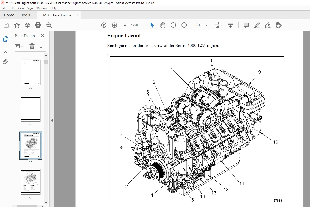
A00000001Engine Layout3
A00000003 Engine Model Designation6
A00000005Engine Side and Cylinder Designations6
A00000009Main Engine Dimensions 8
A00000015Engine Inclinations (Referenced to Water Line) 8
A00000017 General Engine Specifications 9
C OPERATING INSTRUCTIONS11
C00000001Operating Instructions – Introduction13
C00000003Before-Operation Services14
C00000005Initial Operation 15
C00000007Operational Checks -Maintenance Echelon W1- 16
C00000009Engine Shutdown16
C00000011After Engine Shutdown 16
C00000013Out-of-Service Period 17
C00000015Emergency Measures in Event of Engine Malfunction 17
D MAINTENANCE SCHEDULE 19
D00000001 Maintenance Schedule – Introduction 21
D00000003 Maintenance System 21
D00000005 Application Group 22
D00000007 Maintenance Frequency Chart 22
D00000011Maintenance Echelons 23
D00000015Maintenance Echelon M6 26
D00000017Out-of-Service Periods 27
D00000018Maintenance Schedules — Complete System27
E TROUBLESHOOTING 29
E00000001GENERAL31
In Event of Internal Coolant Leakage31
Engine Oil Diluted by Fuel 32
After Work on Engine32
Engine Protection Measures After Penetration by Raw (Sea) Water 32
E00000002Engine does not turn when starter switch/button is operated 33
E00000003Engine turns when starter switch is operated but does not fire34
E00000005Engine fires erratically after starting 36
E00000007Engine does not reach full-load speed 36
All information subject to change without notice
xx Copyright © DETROIT DIESEL CORPORATION
SERIES 4000 12/16V SERVICE MANUAL
E00000009Engine speed not steady 37
E07000001Fuel pressure too low 38
E07305101High Pressure fuel pump leaking at weep hole39
E08000001Fuel pressure too low 39
E10101101Exhaust turbocharger – abnormal running noises40
E11000001Charge air temperature too high 40
E11000003Charge air pressure too low 41
E114105101Intercooler, coolant discharge at Weep Hole 41
E14000001Exhaust gases black42
E14000002Exhaust gases blue 42
E14000003Exhaust gases white43
E17200001Starter power supply faulty44
E18000001Engine oil consumption abnormally high 44
E18000003Engine oil level abnormally high 45
E18000007Engine oil pressure too high 46
E18000009Engine oil pressure too low47
E20200001Engine coolant temperature too high48
E20200003Engine coolant temperature too low 49
E20200005Engine coolant pressure too low 50
E20200007Engine coolant loss 51
E20200009Engine coolant level rising 52
E20205101Engine coolant pump leaking at weep hole53
E20700001Raw water pressure too low 53
E20705101Raw water pump on Weep Hole Leaking 53
G TASK DESCRIPTION55
G00000001Disabling Engine Start59
G00000003Enabling Engine Start 59
G00000005Manual Engine Barring — 12 and 16V engines with remote
marine gears60
G00000007Engine Cranking with Starting System 61
G00000009Engine Starting 62
G00000011Engine Warm-Up62
G00000013Engine Speed Check 63
G00000015Engine Pressure Check63
G00000017Engine Temperature Check 63
G00000019Engine Running Noise Check63
G00000021Engine and External Pipeline Leak Check 63
G00000023Engine Shutdown64
G00000025Emergency Shutdown 64
G00000027Attachments — Securing Bolt Tightness Check 64
G00000029Attachments — Hose and Hose Connections Check64
All information subject to change without notice
Copyright © DETROIT DIESEL CORPORATION xxi
SERIES 4000 12/16V SERVICE MANUAL
G00000033Combustion Chamber Borescope Examination 64
Before the borescope examination 65
Borescope examination:66
Assessment: 67
After the borescope examination 67
G00000039Engine External Cleaning 68
G00000041Welding Operations 70
G01810101Crankcase Breather — Oil Separator Check 71
G03000101Engine Barring Tool Installation 71
G03000103Engine Barring Tool Removal 72
G05500001Valve Gear Oil Supply Check 73
G05500003Valve Gear Lubrication 74
G05505001Valve Clearance Check74
G05505003Valve Clearance Adjustment 75
G05510101Valve Cover Removal 75
G05510103Valve Cover Installation76
G07305107High Pressure Fuel Pump — Weep Hole Obstruction Check 77
G07505101Fuel Injector Removal 77
G07505109Fuel Injector Installation77
G08000003Fuel System Filling 77
G08000005Fuel System Delivery Pump Supply Pressure Check 79
G08305101Fuel Duplex Filter — Operating Position Check 79
G08305103Fuel Duplex Filter — Filter Replacement 80
G08310101Primary Fuel Filter Priming81
G08310103Primary Fuel Filter — Water and Contaminant Draining82
G08310105Primary Fuel Filter Flushing 84
G08310107Primary Fuel Filter Draining 86
G08310109Primary Fuel Filter — Filter Element Replacement 86
G10101101Exhaust Turbocharger — Engine Operation with Faulty Exhaust
Turbocharger87
G11105101Intercooler — Drain Line Coolant Discharge and Obstruction
Check87
Checking coolant outlet on engine A and B sides87
Checking for obstruction88
G11105103Intercooler — Drain Cleaning 88
G12000005Intake Air System — Intake Depression Check 89
G12000007Intake Air System Check 89
G12105101Air Filter Replacement 90
G12305101Air Flow Control Flap — Ease-of- Movement Check91
G14000001Exhaust System Check91
G14000003Exhaust System — Security Check 91
All information subject to change without notice
xxii Copyright © DETROIT DIESEL CORPORATION
SERIES 4000 12/16V SERVICE MANUAL
G14000005Exhaust System — Exhaust Gas Color Check91
G14000007Exhaust System Check92
G14000009Exhaust System — Check Exhaust Back Pressure 92
G14405101Exhaust Flow Control Flap — Ease-of-Movement Check 93
G14600001Exhaust System — Exhaust Pipework Security and Insulation
Check93
G18000001Engine Oil Level Check93
Checking before starting engine 94
Checking after engine shutdown 94
G18000003Engine Oil Filling95
G18000004Engine Oil — Sample Extraction and Analysis96
G18000005Engine Oil Change 96
G18000007Engine Oil Draining 96
G18000009Corrosion Inhibitor Oil Filling 99
G18000011Corrosion Inhibitor Oil Extraction99
G18305201Engine Oil Filter — Operating Position Check100
G18305203Engine Oil Filter Replacement100
G18310101Centrifugal Oil Filter Cleaning102
G20200001Engine Coolant Filling 107
G20200003Engine Coolant Level Check 108
Via Coolant Level Sensor 108
G20200005Coolant — Sample Extraction and Analysis 109
G20200007Engine Coolant Draining 110
G20200009Engine Coolant Change113
G20205101Engine Coolant Pump — Weep Hole Check 114
G20240001Engine Coolant Preheating114
G20240101Engine Coolant Preheating Unit Operation114
G20240103Engine Coolant Preheating Unit — Switching On115
G20240105Engine Coolant Preheating Unit — Switching Off115
G20705101Raw Water Pump — Weep Hole Check115
G20705103Raw Water Pump Priming 116
G20810101Coolant Pressure Cap — Coolant Expansion Tank Opening 116
G20810103Coolant Pressure Cap — Coolant Expansion Tank Closing117
G21000001Wiring — Security and Condition Check 117
G21305101Generator Drive — Coupling Condition Check118
G21305103Generator — Protective Cover Removal 119
G23105101Engine Mounting — Security Check119
G23105103Engine Mounting — Resilient Mount Condition Check 119
G25000001Drive System, Driving End — Security Check119
G25605101Universal Shaft Lubrication120
G25605103Universal Shaft Bearing Clearance Check 121
All information subject to change without notice
Copyright © DETROIT DIESEL CORPORATION xxiii
SERIES 4000 12/16V SERVICE MANUAL
G30700101Guard Check 121
G30900101Battery Check122
G36400001Closing Fuel Supply122
G36400003Opening Fuel Supply 122
G36405001Fuel Supply Check 123
G36500003Exhaust System Drainline Obstruction Check123
G36800001Raw Water Supply Opening 123
G36800003Raw Water Supply Closing123
G36800005Raw Water Draining123
G36800007Raw Water System — Raw Water Pump Supply Pressure
Check124
G36800007Bilge Pump — Weep Hole Check124
G50000001MDEC On 124
G50000003MDEC OFF 125
G50700001MDEC — Plug-In and Threaded Connection Checks 125
G51000001Monitoring System — Monitoring Unit Function Checks125
K STORAGE 127
K00000001Storage – Introduction 129
K00000003Preservation and Storage 130
K00000005Extended Preservation and Storage130
K00000007Restore to Service 131
K00000009Task Descriptions with 3-Digit Codes131
001 Clean engine131
002 Preserve fuel system 131
003 Preserve engine coolant system132
004 Perform preservation run 132
005 Spray corrosion inhibitor oil into air manifolds132
006 Spray corrosion inhibitor oil onto turbocharger compressor wheels 132
007 Seal engine exhaust system 133
008 Seal engine air system133
009 Preserve engine externally 133
011 Inspect and preserve valve gear133
012 Remove seals from engine air system 133
013 remove seals from engine exhaust system 133
T TRANSPORTATION LOCKING DEVICE FOR CRANKSHAFTS 135
T00000001General137
T00000002Transportation Locking Device Removal137
T00000003Transportation Locking Device Installation 137
S SAFETY INSTRUCTIONS T-23
SI00000002 Basic Safety Precautions T-25
SI00000003 Correct UseT-25
All information subject to change without notice
xxiv Copyright © DETROIT DIESEL CORPORATION
SERIES 4000 12/16V SERVICE MANUAL
SI00000005 Personnel RequirementsT-25
SI00000007 Modifications or Conversions T-25
SI00000009 Organizational Measures T-25
SI00000011 Auxiliary MaterialsT-26
SI00000013 Spare PartsT-26
SI00000015 Working Clothes T-26
SI00000017 Transport T-27
SI00000019 Engine Operation T-28
SI00000021 Maintenance and RepairT-29
SI00000023 Environmental Protection T-32
SI00000025 Fire PreventionT-32
SI00000027 Warning SignsT-34
SI00000029 Safety Instructions in the Text T-34
A PRODUCT SUMMARY 141
A00000001 Engine Layout 145
A00000003 Engine Model Designation148
A00000005 Engine Side and Cylinder Designations 149
A00000009 Main Engine Dimensions 150
A00000015 Engine Inclinations151
A00000017 General Engine Specifications 152
A05000001 Timing Data 154
Firing Order154
A05505001 Valve Clearances 155
A18000001 Oil Capacity 155
C OPERATING INSTRUCTIONS 161
C00000001 Operating Instructions – Introduction163
C00000003 Before-Operation Services164
C00000005 Initial Operation 166
C00000007 Operational Checks — Maintenance Echelon W1 166
C00000009 Engine Shutdown 167
C00000011 After-Shutdown Services 167
C00000013 Out-of-Service Period 168
C00000017 Engine Transportation 168
D MAINTENANCE SCHEDULE 169
D00000001 Introduction 171
D00000003 Maintenance System 171
D00000005 Application Group 172
D00000007 Maintenance Frequency Table 172
D00000011 Maintenance Echelons173
G TASK DESCRIPTION 179
G00000001 Disabling Engine Start183
All information subject to change without notice
Copyright © DETROIT DIESEL CORPORATION xxv
SERIES 4000 12/16V SERVICE MANUAL
G00000003 Enabling Engine Start183
G00000005 Manual Engine Barring184
G00000007 Engine Cranking with Starter186
G00000009 Engine Starting 186
G00000011 Engine Warm-Up 186
G00000013 Engine Speed Check 187
G00000015 Engine Pressure Check 187
G00000017 Engine Temperature Check 187
G00000019 Engine Running Noise Check187
G00000021 Engine and External Pipeline Leak Check 188
G00000023 Engine Shutdown 188
G00000025 Emergency Shutdown 188
G00000027 Attachments — Securing Bolt Tightness Check 189
G00000029 Attachments — Hose and Hose Connections Check 189
G00000031 Compression Pressure Check 189
G00000033 Combustion Chamber Borescope Examination 190
Before the Borescope Examination 190
Borescope Examination: 191
Assessment: 192
After the Borescope Examination192
G00000039 Engine External Cleaning193
G03000101 Engine Barring Tool Installation195
G03000103 Engine Barring Tool Removal196
G05500001 Valve Operating Mechanism Oil Supply Check 196
G05500003 Valve Operating Mechanism Lubrication 197
G05505001 Valve Clearance197
G05510101 Cylinder Head Rocker Cover Removal198
G05510103 Cylinder Head Rocker Cover Installation 199
G07305107 High Pressure Fuel Pump — Weep Hole Obstruction Check 200
G07505101 Fuel Injector Removal 200
G07505103 Injector Inspection 200
G07505105 Injector Replacement 201
G07505109 Fuel Injector Installation 201
G08000003 Fuel System Priming 201
G08305103 Fuel Filter Replacement 203
G10101101 Engine Operation with Faulty Turbocharger 204
G10101105 Exhaust Turbocharger Connection Check205
G11105101 Charge Air Cooler — Drain Line Check205
Obstruction Check 206
G11105103 Charge Air Cooler — Drain Cleaning 207
G12000005 Air System — Intake Depression Check 208
All information subject to change without notice
xxvi Copyright © DETROIT DIESEL CORPORATION
SERIES 4000 12/16V SERVICE MANUAL
G12000007 Intake Air System Check 208
G12105101 Air Filter Replacement 208
G12105201 Contamination Indicator Check 208
G14000001 Exhaust System Check208
G14000003 Exhaust System — Security Check209
G14000005 Exhaust System — Exhaust Gas Color Check 209
G14000009 Exhaust System — Check Exhaust Back Pressure209
G14600001 Exhaust System — Exhaust Pipework Security and Insulation
Check209
G17205107 Starter, Cable Security and Condition Check209
G18000001 Engine Oil Level Check210
Checking before starting engine 210
Checking after engine shutdown 210
G18000003 Engine Oil Filling211
G18000004 Engine Oil — Sample Extraction and Analysis 212
G18000005 Engine Oil Change 212
G18000007 Engine Oil Draining213
G18000009 Corrosion Inhibitor Oil Filling 214
G18000011 Corrosion Inhibitor Oil Extraction214
G18305203 Engine Oil Filter Replacement 215
G18310101 Centrifugal Oil Filter Cleaning216
G20200001 Engine Coolant Filling 223
G20200003 Engine Coolant Level Check 225
G20000005 Coolant — Sample Extraction and Analysis 227
G20200007 Engine Coolant Draining 227
G20200009 Engine Coolant Change 230
G20205101 Engine Coolant Pumps — Weep Hole Check (Relief Bore) 231
G20240001 Engine Coolant Preheating 231
G20240101 Engine Coolant Preheater Operation 231
G20265101 Engine Coolant System — Vent Line Obstruction Check 232
G20300001 Charge Air Coolant System Filling 232
G20300003 Charge Air Coolant Level Check232
G20300005 Charge Air Coolant Draining 233
G20355101 Charge Air Coolant System Vent Line Obstruction Check 234
G20505101 Engine Coolant Radiator Core External Contamination Check 234
G20505103 Charge Air Coolant Radiator Elements External Contamination
Check235
G20605301 Coolant Pressure Cap — Radiator Expansion Tank Opening235
G20605303 Coolant Pressure Cap — Radiator Expansion Tank Closing 236
G21000001 Wiring — Security and Condition Check 236
All information subject to change without notice
Copyright © DETROIT DIESEL CORPORATION xxvii
SERIES 4000 12/16V SERVICE MANUAL
G21305101 Alternator Drive — Vee-ribbed Belt Condition and Tension
Check236
Damage Pattern of Vee-ribbled Belts237
Tension Check239
G21305105 Alternator Drive — Vee-ribbed Belt Replacement 239
G21305107 Security Check 240
G22105101 Fan Drive — Vee-ribbed Belt Condition and Tension Check 240
G22105103 Fan Drive — Vee-ribbed Belt Replacement 243
G23105101 Engine Mount — Security Check243
G23105103 Engine Mount — Resilient Mount Condition Check 244
G25000001 Crankshaft Pulley — Security Check 244
G25905101 Air Compressor Drive 244
G30700101 Guard Check244
G30900101 Battery Check 245
G36400101 Fuel Supply Cut Out 245
G36400103 Fuel Supply Cut In 245
G36405001 Fuel Supply Check 246
G36500003 Exhaust System Drainline Obstruction Check246
G50000001 Engine Control System Cut In 246
G50000003 Engine Control System Cut Out 246
G50000005 Preparation for Welding Operations247
G50000007 DDEC — Operation247
G50700001 DDEC Connection Checks 247
G51000001 Monitoring System 247
K PRESERVATION 249
K00000001 Preservation — Introduction 251
K00000003 Preservation and Storage 252
K00000005 Extended Preservation and Storage253
K00000007 Restore to Service 253
K00000009 Task Descriptions with Three-Digit Codes253
001 Clean engine254
002 Preserve fuel system 254
003 Preserve engine coolant system254
004 Perform preservation run 254
005 Spray corrosion inhibitor oil into air manifolds254
006 Spray corrosion inhibitor oil onto turbocharger compressor wheels 255
007 Seal engine exhaust system 255
008 Seal engine air system255
009 Preserve engine externally 255
011 Inspect and preserve valve gear256
012 Remove seals from engine air system 256
All information subject to change without notice
xxviii Copyright © DETROIT DIESEL CORPORATION
SERIES 4000 12/16V SERVICE MANUAL
013 Remove seals from engine exhaust system 256
All information subject to change without notice
Copyright © DETROIT DIESEL CORPORATION xxix
SERIES 4000 12/16V SERVICE MANUAL
All information subject to change without notice
xxx Copyright © DETROIT DIESEL CORPORATION
A – GENERAL INFORMATION
Section Page
A 001 IMPORTANT INFORMATION A -3
A 002 GENERAL ENGINE INFORMATION A -11
A 003 TORQUE SPECIFICATIONS A -23
A 004 SAFETY PRECAUTIONS A -33
A 005 GENERAL DESCRIPTION OF SERIES 4000 OPERATIONA -47
A 006 DATA SHEETS A -51
A 007 CONVERSION TABLES A -65
A 008 REPAIRING THREADED BORES A -71
Questions? Email us: [email protected]
https://vimeo.com/858542101?share=copy
DESCRIPTION:
MTU DDC Series 4000 12V 16V Diesel & Diesel Marine Engines Service Manual 6SE4011 PDF DOWNLOAD
Basic Requirements for Maintenance and Service Work
- All safety regulations are observed.
- Good general-purpose tools are provided.
- Cleaning and testing equipment is provided.
- Work is performed by trained personnel.
- Special tools are provided.
- Service area is adequately equipped.
- Component cleanliness: Areas of all components that come into contact with oil, fuel, coolant, water, and combustion air must be kept clean.
- Components requiring special cleanliness (e.g. oil and fuel-carrying components) must be cleaned with suitable cleaning procedures before assembly and then checked for cleanliness and treated accordingly.
- Component packaging must only be removed immediately before installation.
- Elastomer components (e.g. rubber parts, etc.) must not be washed with diesel fuel, solvents, or cold cleaners.
- Parts dirtied with oil and fuel must be cleaned immediately. The parts should be wiped with a dry cloth.
- Elastomer components such as engine mounts, damping elements, couplings, and Vee-belts must not be painted. They can only be installed after painting the engine or must be covered before painting work is carried out.
- Radial-lip shaft seals treated with oil by the manufacturer show definite signs of swelling when delivered. They must, therefore, be cleaned (not washed) only with an abrasion-proof paper towel before installation.
- The surfaces of parts that slide against each other must be lubricated with engine oil when installed, unless otherwise specified.
- O-rings and surfaces moving against them during installation (bores and shafts) must be coated with petroleum jelly unless otherwise specified.
- O-rings must be installed in shaft grooves without twists. To remove twists, pass a rounded marking tool under the sealing ring along the circumference (if O-ring diameter is sufficiently large).
- Before shaft seal installation:
- The sealing lip of the shaft seal (except teflon-type seals) must be coated with petroleum jelly, and the shaft running surface with thin-film lubricant or engine oil.
- Teflon seals used in the front and rear main seals must be installed dry.
- The outer surface of metal outer jackets in the support bore must be coated with surface sealant unless otherwise specified in the drawing. For elastomer outer jackets or combined metal/elastomer outer jackets, the outer surface must be coated with denatured ethanol.
PLEASE NOTE:
- This is the same manual used by the dealers to diagnose and troubleshoot your vehicle
- You will be directed to the download page as soon as the purchase is completed. The whole payment and downloading process will take anywhere between 2-5 minutes
- Need any other service / repair / parts manual, please feel free to contact [email protected] . We still have 50,000 manuals unlisted
G.P